CTP2000 4WE&M Interface Module
The CTP2000 Series 4WE&M interface module has eight 4-wire E&M ports. It is used with voice compression (VCOMP) bundles in CTP2000 models and can be used only with a CTP2000 compression module. You can use the 4WE&M interface module to interconnect analog 4WE&M voice applications with CESoPSN bundles.
You can use the eight port T1/E1 interface module to interconnect digital voice applications with CESoPSN bundles.
Four-wire audio interfaces with E and M signaling interfaces (4WE&M) are commonly used as trunks between a central office (CO) and a private branch exchange (PBX). E and M is a type of supervisory line signaling that uses separate leads, called the "E" (ear) lead and "M" (mouth) lead and are traditionally used in the telecommunications industry. In 4WE&M signaling, two wires are used to receive and two wires are used to transmit, incorporating simplex control and differential payload in each channel. Type I, II, and V signaling is supported.
The 4WE&M interface module consists of a front card and a rear transition module (RTM). Port interfaces are located on connectors A and B of the RTM. (See Figure 1 and Figure 2.) The RJ-45 connectors are not used.
Power to the RTM is supplied from the interface module. Using an RTM other than those matched to the interface module may result in damage to both the interface module and the RTM. For example, never install a clock module RTM directly behind a 4WE&M interface module.
Voice ports can be used only by voice compression bundles (VCOMP) and cannot be used for CTP, SAToP, or CESoPSN bundles. There is no software configuration of 4WE&M ports. Signaling type is configured by means of jumpers (see Figure 4 and Table 1). One or more 4WE&M ports can be mapped to a VCOMP bundle. The bundle configuration specifies the remote destination, the local port or ports transported by the bundle, voice compression options, as well as other configuration options.
Jumper JP17 must be in Position 1-2 (see Table 1) if any ports are set for Type II signaling. This jumper ties all signal battery (SB) signals to battery voltage (–48V).
Jumper JP26 is used to connect all signal grounds (SG) to the chassis ground. When jumper JP26 is in Position 1-2, the signal ground is connected to the chassis ground. In Position 2-3, it is isolated from the chassis ground.
|
Jumper |
Signaling Type I |
Signaling Type II |
Signaling Type V |
|---|---|---|---|---|
Port 0 |
JP1 |
Position 1-2 |
Position 2-3 |
Position 1-2 |
JP9 |
Position 2-3 |
Position 2-3 |
Position 1-2 |
|
Port 1 |
JP2 |
Position 1-2 |
Position 2-3 |
Position 1-2 |
JP10 |
Position 2-3 |
Position 2-3 |
Position 1-2 |
|
Port 2 |
JP3 |
Position 1-2 |
Position 2-3 |
Position 1-2 |
JP11 |
Position 2-3 |
Position 2-3 |
Position 1-2 |
|
Port 3 |
JP4 |
Position 1-2 |
Position 2-3 |
Position 1-2 |
JP12 |
Position 2-3 |
Position 2-3 |
Position 1-2 |
|
Port 4 |
JP5 |
Position 1-2 |
Position 2-3 |
Position 1-2 |
JP13 |
Position 2-3 |
Position 2-3 |
Position 1-2 |
|
Port 5 |
JP6 |
Position 1-2 |
Position 2-3 |
Position 1-2 |
JP14 |
Position 2-3 |
Position 2-3 |
Position 1-2 |
|
Port 6 |
JP7 |
Position 1-2 |
Position 2-3 |
Position 1-2 |
JP15 |
Position 2-3 |
Position 2-3 |
Position 1-2 |
|
Port 7 |
JP8 |
Position 1-2 |
Position 2-3 |
Position 1-2 |
JP16 |
Position 2-3 |
Position 2-3 |
Position 1-2 |
The rear transition board uses two RJ-21 25-pair Telco connectors labeled A and B to interface the audio and control connections for eight E&M channels.
Because of space limitations, a 180º RJ-21 connector is required. The CTP 4WE&M RTM supports clips to secure the RJ-21 cable connections to the RTM.
The R1/T1 pair and the R/T pair are the audio inputs and outputs of each port, respectively. For example, the audio input pair for port 0 is R1 and T1 on pins 2 and 27 of connector A. The audio output pair for port 0 is R and T on pins 1 and 26.
See Table 2 for signal definitions. See CTP2000 4WE&M Interface Connector Pinouts for the connector A and B pinouts.
Signal Name |
Signal Definition |
|---|---|
Port x T, R |
Audio transmit pair, 600 Ohm |
Port x T1, R1 |
Audio receive pair, 600 Ohm |
Port x E |
E lead–output |
Port x M |
M lead–input |
Port x SG |
Input for signal ground for signaling type II |
Port x SB |
Output signal battery (–48V) for signaling type II. Note that JP17 must be in position 1-2. |
GND |
Signal ground. E and M leads are referenced to this ground for signaling types I and V. Use JP26 to connect this ground to chassis ground. |
Supervisory Signaling
Supervisory signaling is the means by which a telephone user requests a service or initiates a call. The signaling unit (CTP platform) interacts with the trunk unit (PBX) by means of either two or four leads, depending on the signaling type. (See Figure 5.) The signaling unit controls the E lead, whereas the trunk side controls the M lead. The two signaling states are on-hook and off-hook. During inactivity both units are on-hook. See Table 3 for a summary of signaling types supported by the CTP2000 4WE&M module.
4WE&M and 4WTO audio paths are always up independent of the signaling state.
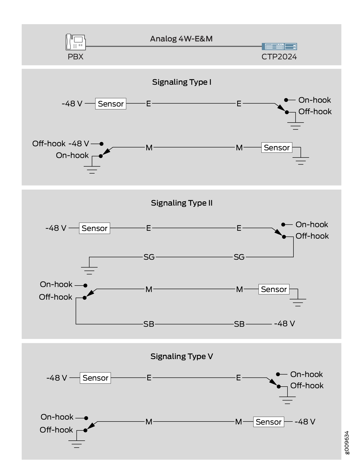
Type I uses two leads—the E and M leads—for signaling. During inactivity, the E lead is open and the M-lead is connected to ground. The CTP device connects the E lead to a grounding point to signal off-hook, and the PBX connects the M lead to the battery (–48 V) to signal off-hook. Note that two signaling units cannot be connected back-to-back. With type I signaling, the signaling and trunk units must be connected by means of a common ground. Because the two sides are not isolated, they are susceptible to noise in the audio channels.
Type II uses four leads—E, SG, M, and SB—for signaling. During inactivity, both the E and M leads are open. To signal off-hook, the PBX connects the M lead to SB and the CTP device connects the E lead to SG. Note that two signaling units can be connected back-to-back if the appropriate signaling leads are swapped. With Type II signaling, the signaling unit and the trunk do not share a common ground.
Type V uses two leads, the E and M leads, for signaling. During inactivity, both the E and M leads are open. The CTP device signals off-hook by connecting the E lead to ground. The trunk circuit signals off-hook by connecting the M lead to ground. As with type I, with type V signaling, the two units share a common ground. Type V signaling allows for signaling units to be connected back-to-back.
Signaling Type |
Signaling Leads |
PBX (M Lead) |
CTP (E Lead) |
||
|---|---|---|---|---|---|
| On-hook | Off-hook | On-hook | Off-hook | ||
I |
E, M |
Ground |
Battery |
Open |
Ground |
II |
E, M, SG, SB |
Open |
SB |
Open |
SG |
V |
E, M |
Open |
Ground |
Open |
Ground |