Help us improve your experience.

Let us know what you think.

Do you have time for a two-minute survey?


Removing a CTP Interface Module, Processor Module, or Clock Module

To remove a CTP module:

  1. Issue the halt command.
  2. Power off the CTP151 device.
  3. Wrap and fasten one end of the ESD grounding strap around your wrist and connect the other end to a site ESD point.
  4. Use a Phillips screwdriver to loosen the captive screws located at the upper right and upper left of the module panel.
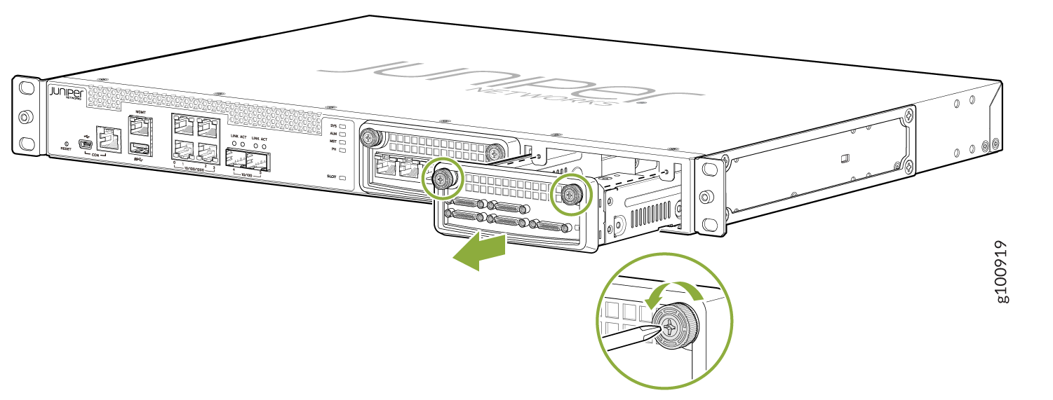
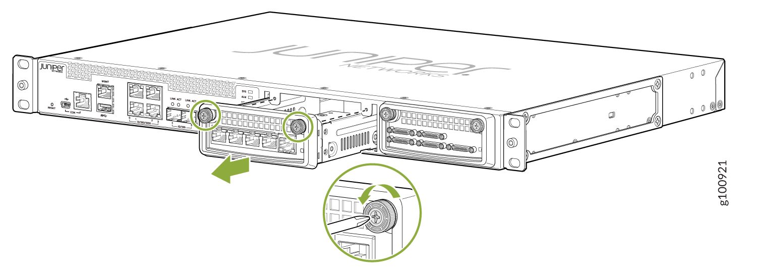
  5. Hold the captive screws and gently pull them outward to remove the module. See Figure 1.
    Figure 1: Removing Serial and T1/E1 Interface ModulesJuniper Networks device front panel with Ethernet, SFP, and console ports. Module removal shown with green arrows and screws being loosened.Juniper Networks device front panel with ports and removable module instructions for screw mechanism removal.
  6. Carefully slide the module out of the chassis.
  7. Place the module in its antistatic bag, being careful not to touch module components, pins, leads or solder connections.
  8. Cover the empty chassis slot with a blank filler panel, and tighten the filler panel's captive screws using a Phillips screwdriver. Turn both screws several times before tightening them completely.