Help us improve your experience.

Let us know what you think.

Do you have time for a two-minute survey?


Replace Direct Attach Cables

A direct attach cable has a transceiver preattached to each end.

Disconnect a Direct Attach Cable

Ensure that you have the following parts and tools available:

  • An antistatic bag or an antistatic mat to store the cable, if you are disconnecting the cable from both the ports it is connected to

  • Rubber safety caps to cover the ports on the device, or a replacement cable

  • Rubber safety caps to cover the transceivers at the ends of the cable

  • An electrostatic discharge (ESD) grounding strap—not provided

To disconnect a direct attach cable:

  1. Disable the port to which the cable is connected by issuing the following command:
  2. Place the antistatic bag or antistatic mat on a flat, stable surface if you are disconnecting the cable from both the ports it is connected to.
  3. Wrap and fasten one end of the ESD wrist strap around your bare wrist, and connect the other end of the strap to a site ESD point.
  4. Label the cable so that you can reconnect it correctly.
    CAUTION:

    Do not leave the transceivers at the ends of the cable uncovered except when connecting or disconnecting the cable. The rubber safety cap keeps the transceivers clean and protected.

    CAUTION:

    Do not bend the cables beyond their minimum bend radius. An arc smaller than a few inches in diameter can damage the cables and cause problems that are difficult to diagnose.

    CAUTION:

    Do not let the cables hang free from the connector. Do not allow fastened loops of cables to dangle, which stresses the cables at the fastening point.

  5. By using your fingers, pull the tab on the transceiver attached to the cable to disengage it.
    Figure 1: Disconnect an SFP28 or SFP+ Direct Attach Cable
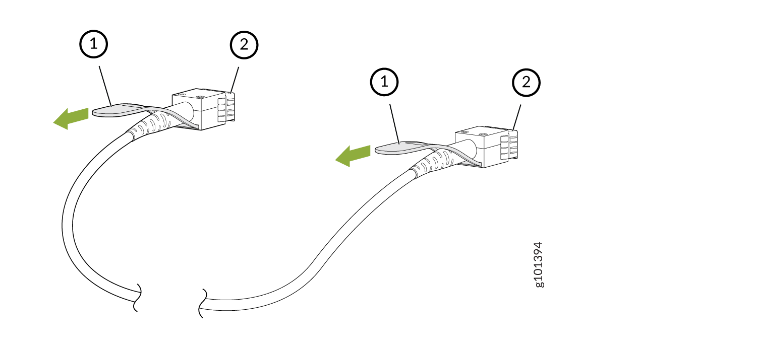
 Diagram of an Ethernet cable with an RJ45 connector highlighting the clip for securing and releasing the connector from a port.

    Callout

    Item

    1

    Tab to pull the transceiver

    2

    Port on the device

    Figure 2: Disconnect a QSFP-DD Direct Attach Cable
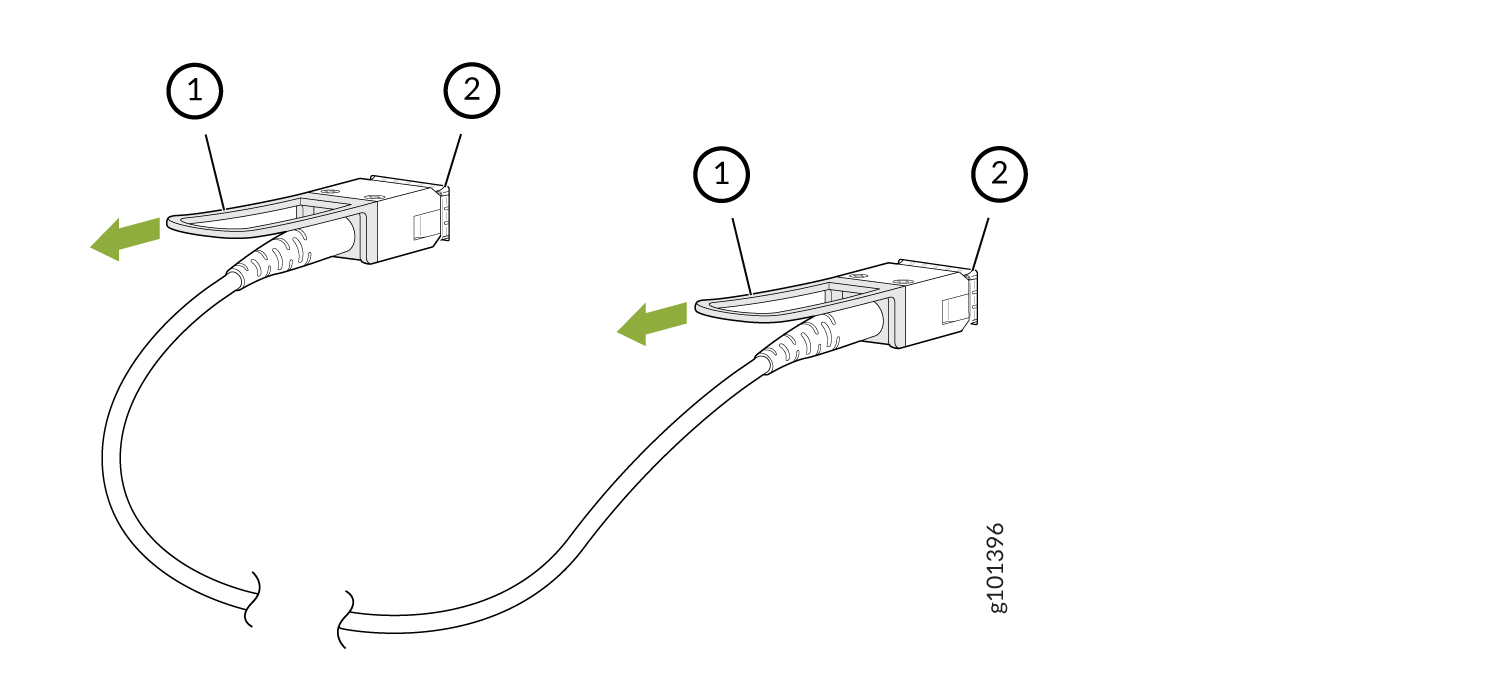
 Diagram showing how to connect or disconnect two cable connectors labeled 1 and 2 with green arrows indicating direction.

    Callout

    Item

    1

    Tab to pull the transceiver

    2

    Port on the device

  6. Grasp the transceiver and gently slide it approximately 0.5 in. (1.3 cm) straight out of the port.
    CAUTION:

    To prevent ESD damage to the transceiver, do not touch the connector pins at the end of the transceiver.

  7. By using your fingers, grasp the body of the transceiver and pull it straight out of the port.
  8. Cover the transceiver with a rubber safety cap.
  9. If you are disconnecting the cable from both the ports it is connected to, place the cable in the antistatic bag or on the antistatic mat placed on a flat, stable surface.

The procedure to disconnect other types of direct attach cables, other than direct attach breakout cables, is the same as the procedure described in this topic.

Connect a Direct Attach Cable

CAUTION:

To prevent ESD damage to the transceiver, do not touch the connector pins at the end of the transceiver.

Ensure that you have an ESD grounding strap (not provided).

Note:

After you connect a cable or after you change the media-type configuration, wait for 6 seconds for the interface to display operational commands.

We recommend that you use only cables purchased from Juniper Networks with your Juniper Networks device.

CAUTION:

The Juniper Networks Technical Assistance Center (JTAC) provides complete support for Juniper-supplied optical modules and cables. However, JTAC does not provide support for third-party optical modules and cables that are not qualified or supplied by Juniper Networks. If you face a problem running a Juniper device that uses third-party optical modules or cables, JTAC may help you diagnose host-related issues if the observed issue is not, in the opinion of JTAC, related to the use of the third-party optical modules or cables. Your JTAC engineer will likely request that you check the third-party optical module or cable and, if required, replace it with an equivalent Juniper-qualified component.

Use of third-party optical modules with high-power consumption (for example, coherent ZR or ZR+) can potentially cause thermal damage to or reduce the lifespan of the host equipment. Any damage to the host equipment due to the use of third-party optical modules or cables is the users’ responsibility. Juniper Networks will accept no liability for any damage caused due to such use.

To connect a direct attach cable:

  1. Wrap and fasten one end of the ESD wrist strap around your bare wrist, and connect the other end of the strap to a site ESD point.
  2. Remove the cable from its bag.
  3. If the transceiver attached to the cable is covered with a rubber safety cap, remove the cap. Save the cap.
    CAUTION:

    Do not leave the transceivers at the ends of the cable uncovered except when connecting or disconnecting the cable. The rubber safety cap keeps the transceivers clean and protected.

  4. If the port on the device is covered with a rubber safety cap, remove the cap. Save the cap. If you are hot-swapping a cable, wait for at least 10 seconds after removing the cable from the port before installing a new cable.
    CAUTION:

    Before you slide the transceiver into the port, ensure that the transceiver is aligned correctly. Misalignment might cause the pins to bend, making the cable unusable.

  5. By using both hands, carefully insert the transceiver in the empty port. The connectors must face the chassis. Slide the transceiver in gently until it is fully seated.
    Figure 3: Connect an SFP28 or SFP+ Direct Attach Cable
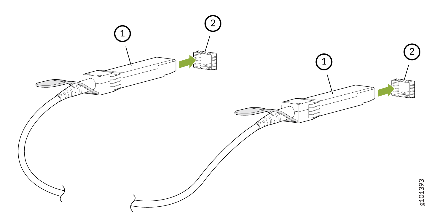
 Diagram of two network cables labeled 1 and 2 with connectors being inserted into ports, guided by green arrows.

    Callout

    Item

    1

    Transceiver

    2

    Port on the device

    Figure 4: Connect a QSFP-DD Direct Attach Cable
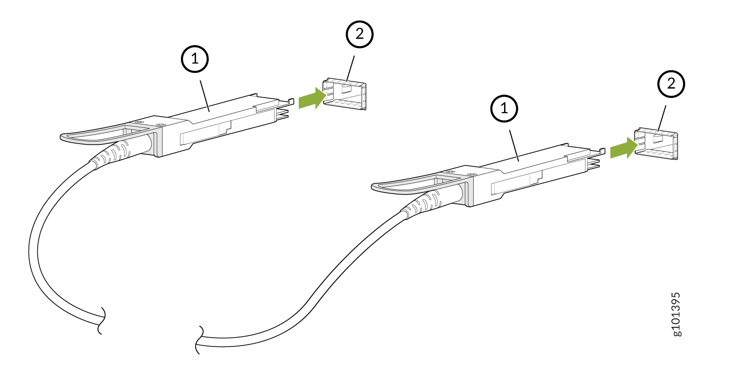
 Diagram showing two cable connectors labeled 1 and two ports labeled 2 with green arrows indicating insertion directions.

    Callout

    Item

    1

    Transceiver

    2

    Port on the device

  6. Repeat Step 5 for the other port to which the cable must be connected.
  7. Secure the cable so that it does not support its own weight as it hangs to the floor. If there is a cable management system, arrange the cable in the cable management system to prevent the cable from dislodging or developing stress points. Place excess cable out of the way in a neatly coiled loop in the cable management system. Placing fasteners on the loop helps to maintain its shape.
    CAUTION:

    Do not bend the cables beyond their minimum bend radius. An arc smaller than a few inches in diameter can damage the cables and cause problems that are difficult to diagnose.

    CAUTION:

    Do not let the cables hang free from the connector. Do not allow fastened loops of cables to dangle, which stresses the cables at the fastening point.

The procedure to connect other types of direct attach cables, other than direct attach breakout cables, is the same as the procedure described in this topic.