ON THIS PAGE
Mount the AP64 Access Point
You can mount the AP64 either on a wall or on a pole using two methods—flush mount or articulating mount.
Mounting Brackets for AP64
- Mounting Brackets for Flush Mount Method
- Mounting Brackets for New Flush Mount Method
- Mounting Brackets for Articulating Mount Method
We ship the AP64 with the APOUTBR-FM2 flush mount brackets. You can order the articulating mount brackets separately.
Table 1 lists the part numbers for the mounting brackets.
| Part Number | Description |
|---|---|
| APOUTBR-FM | Flush mount brackets |
| APOUTBR-FM2 | Flush mount brackets (new) |
| APOUTBR-ART2 | Articulating mount brackets |
Mounting Brackets for Flush Mount Method
The mounting accessories for flush mounting include the following:
-
One flush mount bracket (part number: APOUTBR-FM)
-
Two hose clamps
-
Four M6 screws
-
Four sets of M6 screws, washers, and spring washers
-
Five sets of anchors and screws
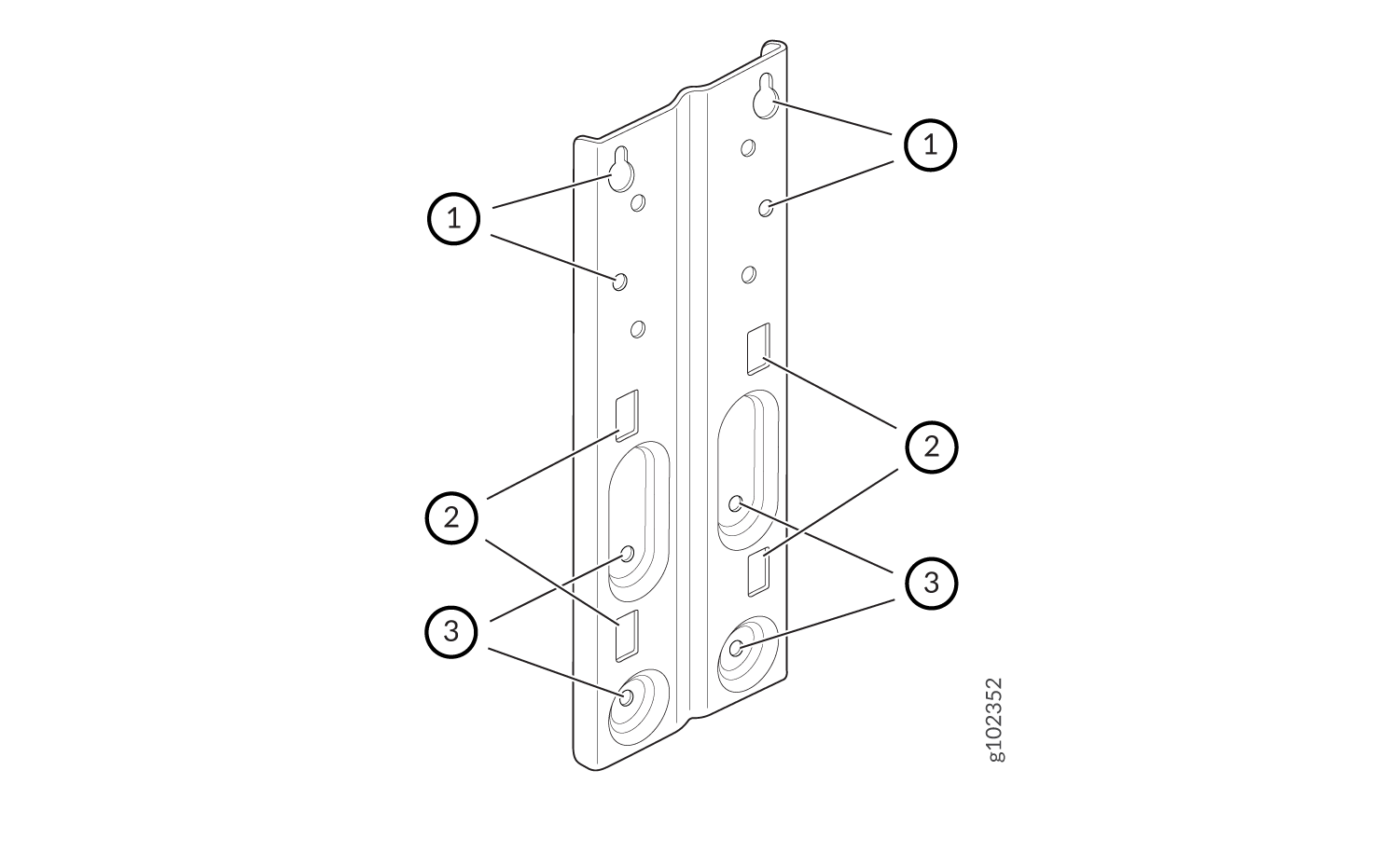
| 1—Screw holes to use for mounting an AP63 on a wall | 2—Holes to use for attaching hose clamps |
| 3—Screw holes to use for attaching the bracket to an AP63 |
Mounting Brackets for New Flush Mount Method
The mounting accessories for flush mounting include the following:
One flush mount bracket (part number: APOUTBR-FM2)
-
Two hose clamps
-
Four sets of M6 screws, washers, and lock washers
-
Five sets of anchors and screws
Mounting Brackets for Articulating Mount Method
The mounting accessories for articulating mounting include the following:
-
Three mounting brackets (part number: APOUTBR-ART2):
Mounting bracket 1
Mounting bracket 2
Mounting bracket 3
-
Four M6x10mm screws
-
Four bolts and nuts
Connect the Grounding Cable
We recommend that you ground the AP before mounting it on a wall or pole. The AP64 has a single-hole protective grounding terminal on the rear. Use this grounding terminal to ground the AP.
To ground the AP64:
- Remove the screw.
- Place the grounding lug attached to the grounding cable over the grounding terminal.
- Secure the grounding cable lug to the grounding terminal with the screw.
Mount the AP64 on a Wall Using APOUTBR-FM (Flush Mount)
-
Attach the APOUTBR-FM flush mount bracket to the AP by using the four
screws, washers, and lock washers provided along with the AP. Use the
bracket screw holes marked with callout #3 in Figure 1.
Figure 2: Attach the APOUTBR-FM Flush Mount Bracket to an AP64
-
Position the AP such that the two screws that you inserted in Step 1 fit
into the holes in the bracket. Slide the AP
downward
so that the screws lock in place.
Figure 3: Mount an AP64 on a Wall (Flush Mount)
Mount the AP64 on a Pole Using APOUTBR-FM (Flush Mount)
-
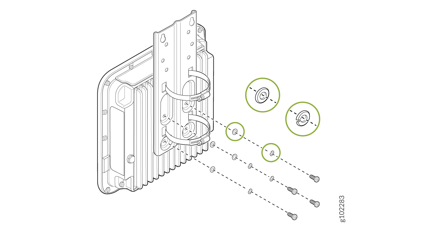
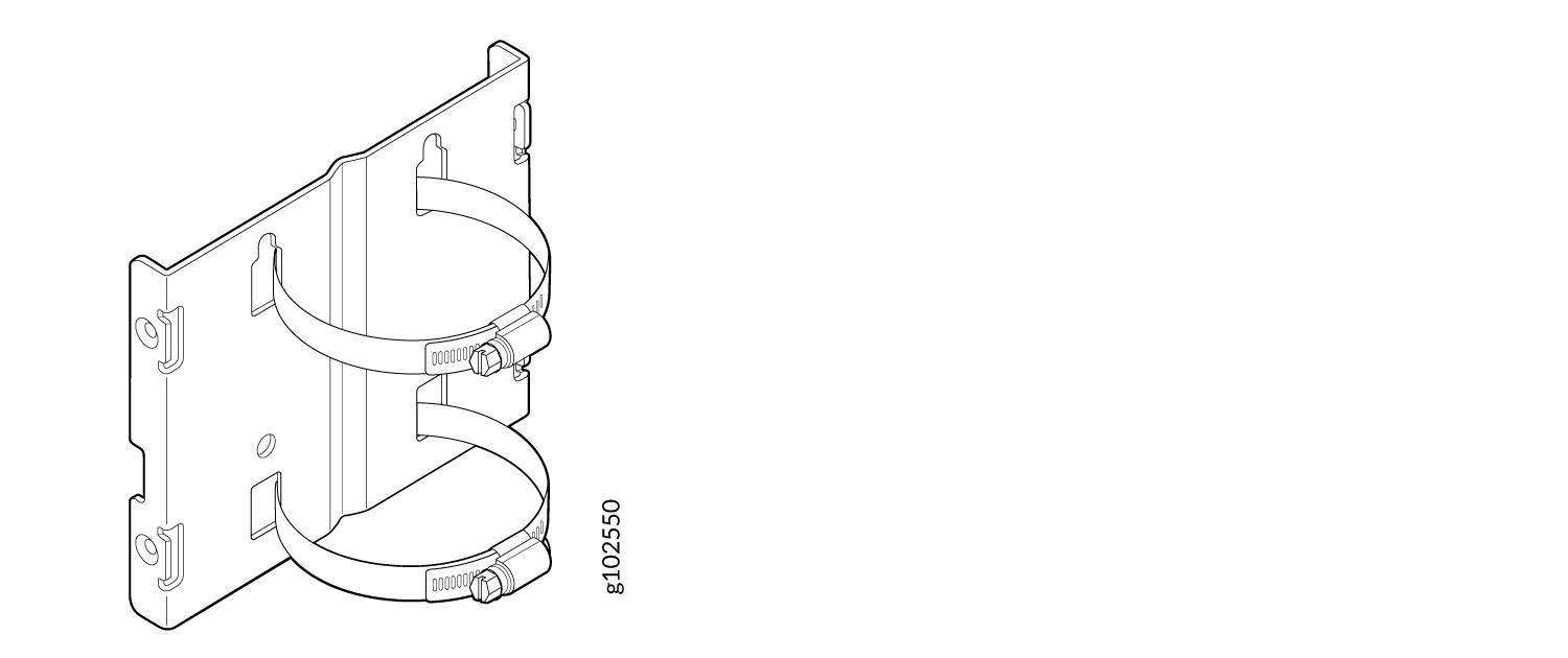
Attach the hose clamps to the APOUTBR-FM flush mount bracket. Use a
screwdriver to release the hose clamps and then pass the hose clamps through
the slots in the flush mount bracket.
Figure 4: Attach Hose Clamps to the APOUTBR-FM Flush Mount Bracket

-
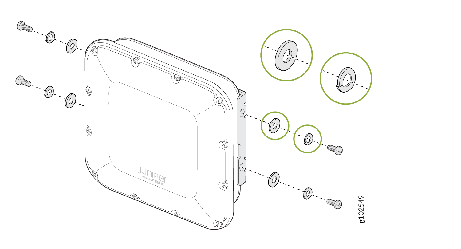
Attach the APOUTBR-FM flush mount bracket to the AP by using the four
screws, washers, and lock washers provided along with the AP.
Figure 5: Attach the APOUTBR-FM Flush Mount Bracket to an AP64
-
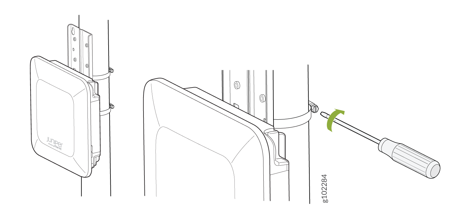
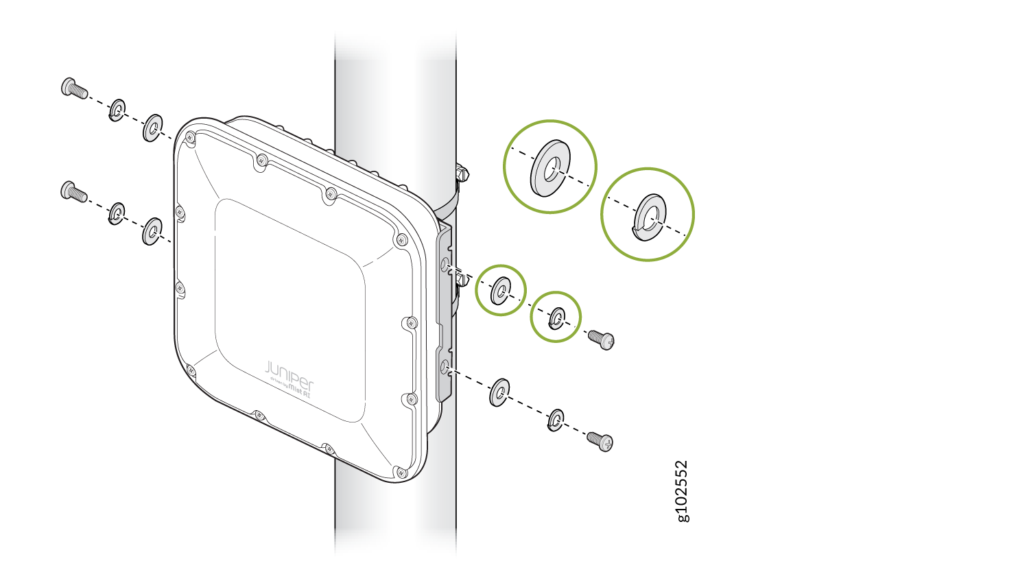
Mount the AP on the pole. Wind the open end of the hose clamps around the
pole and tighten the hose clamp screws by using a screwdriver. Tighten the
screws until the AP and bracket assembly are secured in place.
Figure 6: Mount an AP64 on a Pole (Flush Mount)
Mount the AP64 on a Wall Using APOUTBR-FM2 (Flush Mount)
-
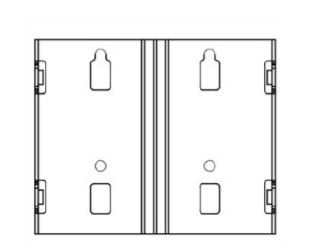
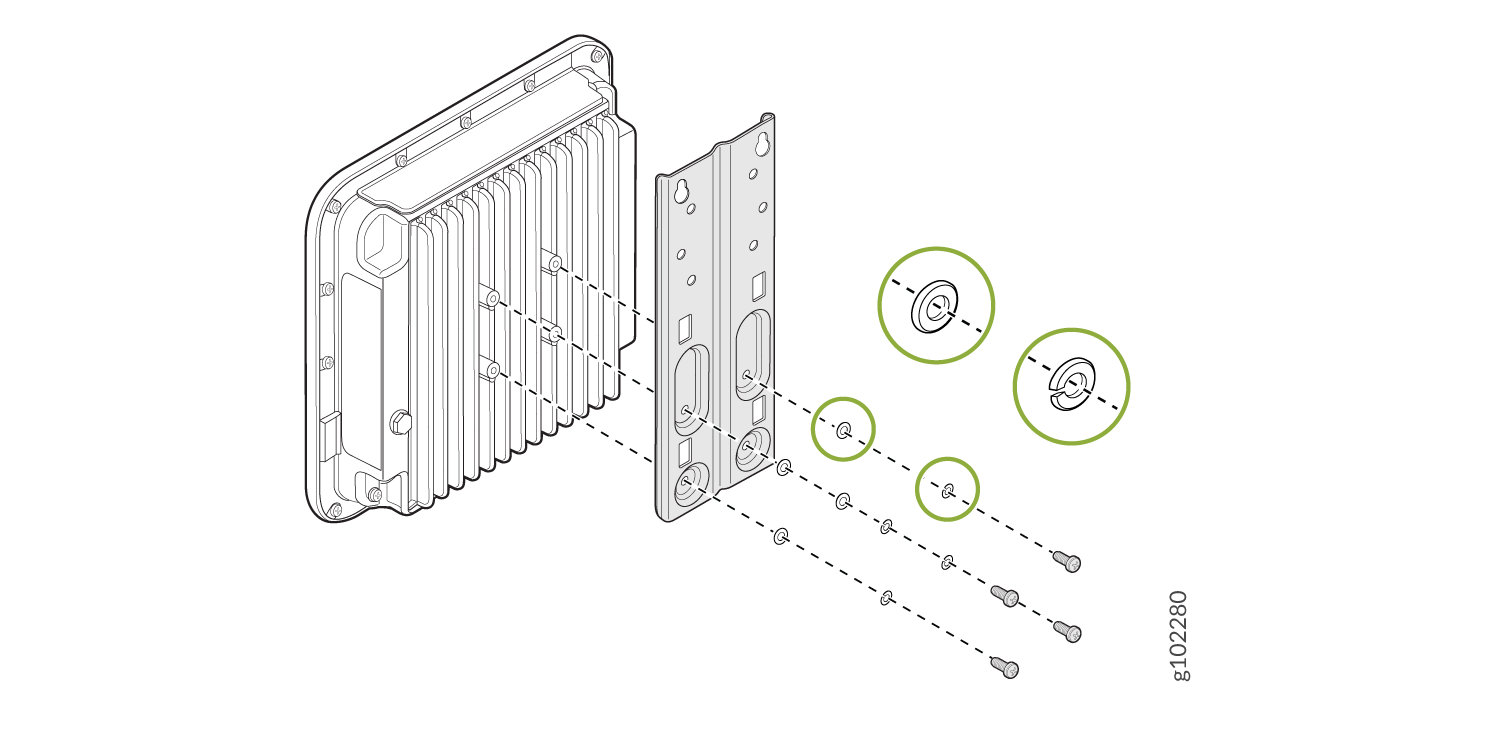
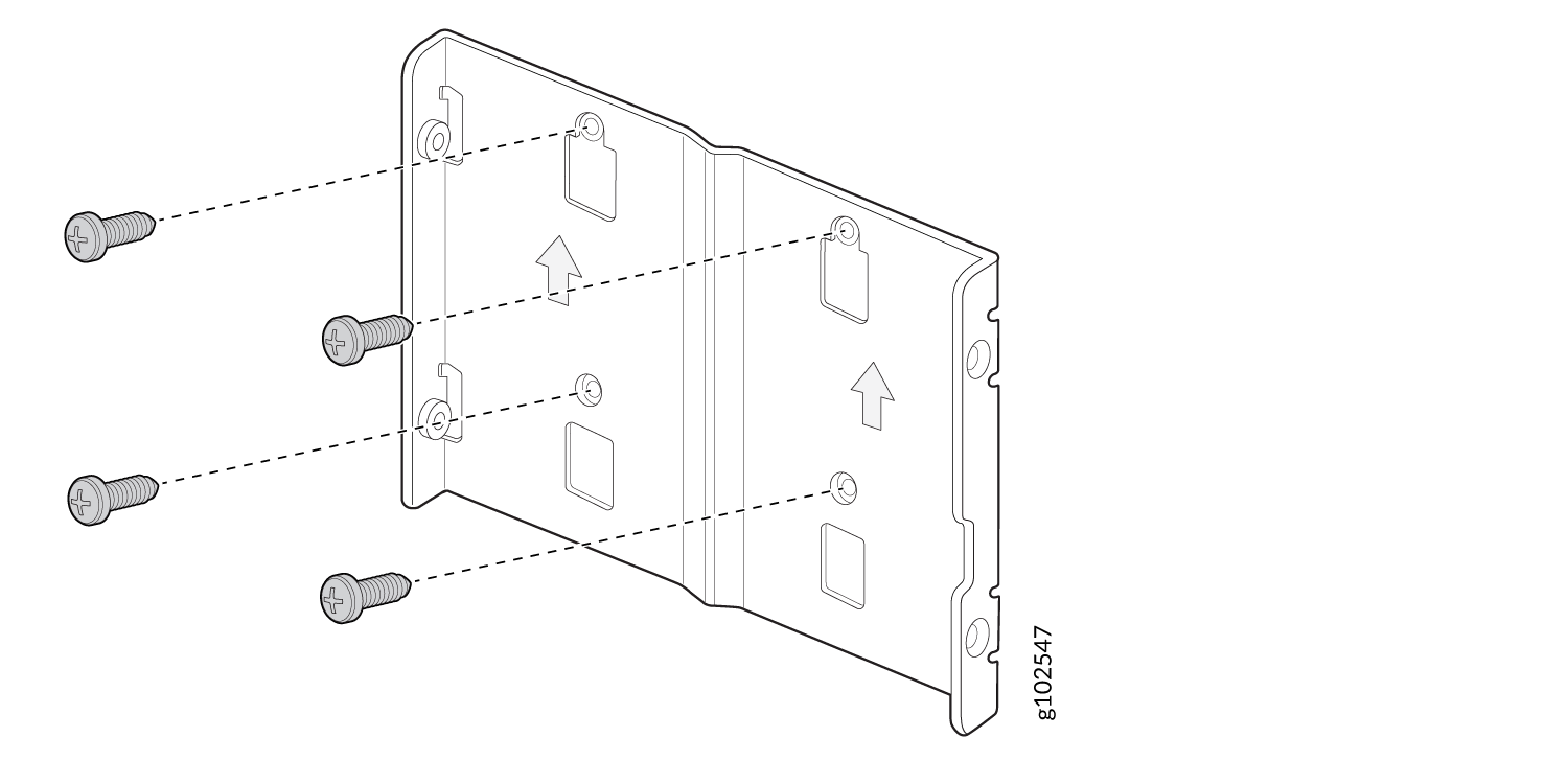
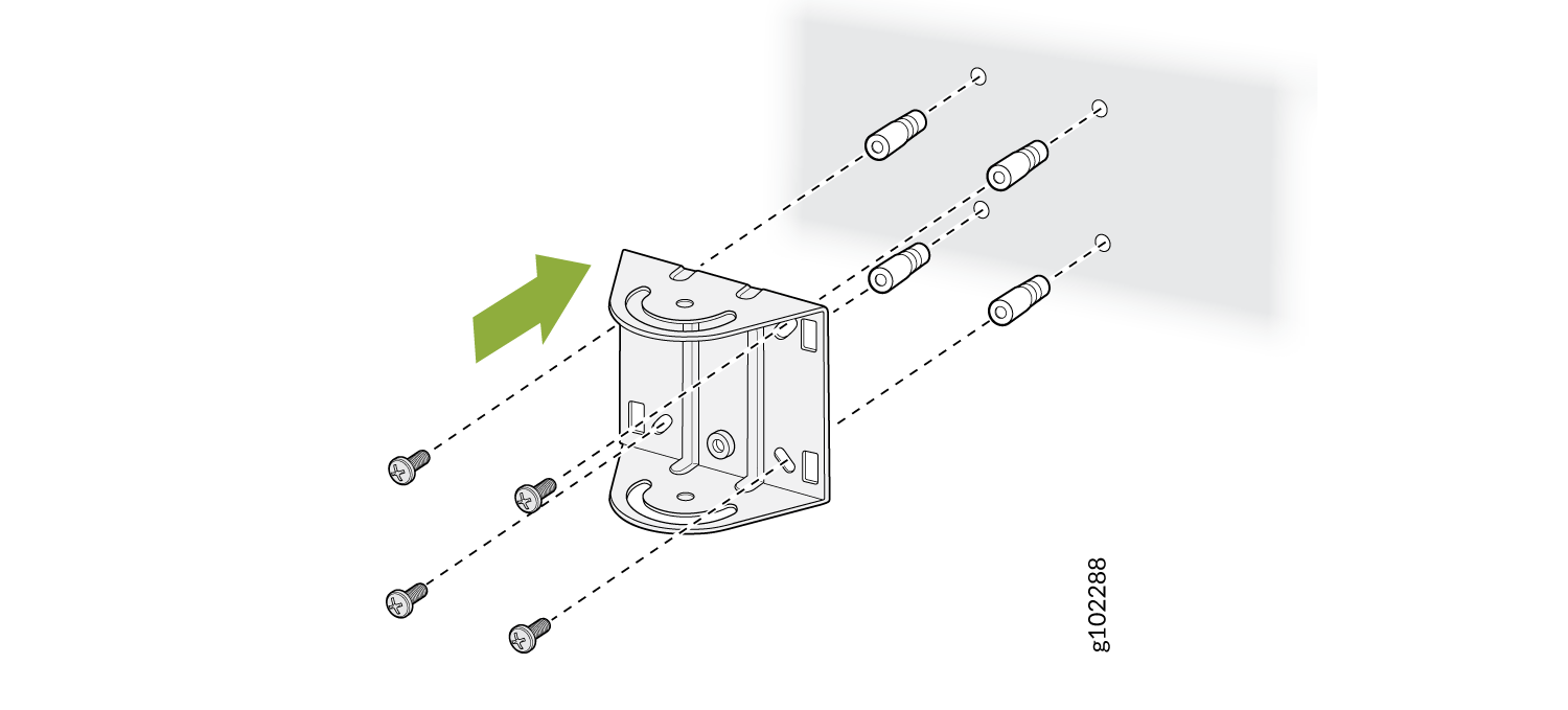
Install the APOUTBR-FM2 mounting bracket on the wall using the four
screws.
Figure 7: Install the APOUTBR-FM2 Mounting Bracket
-
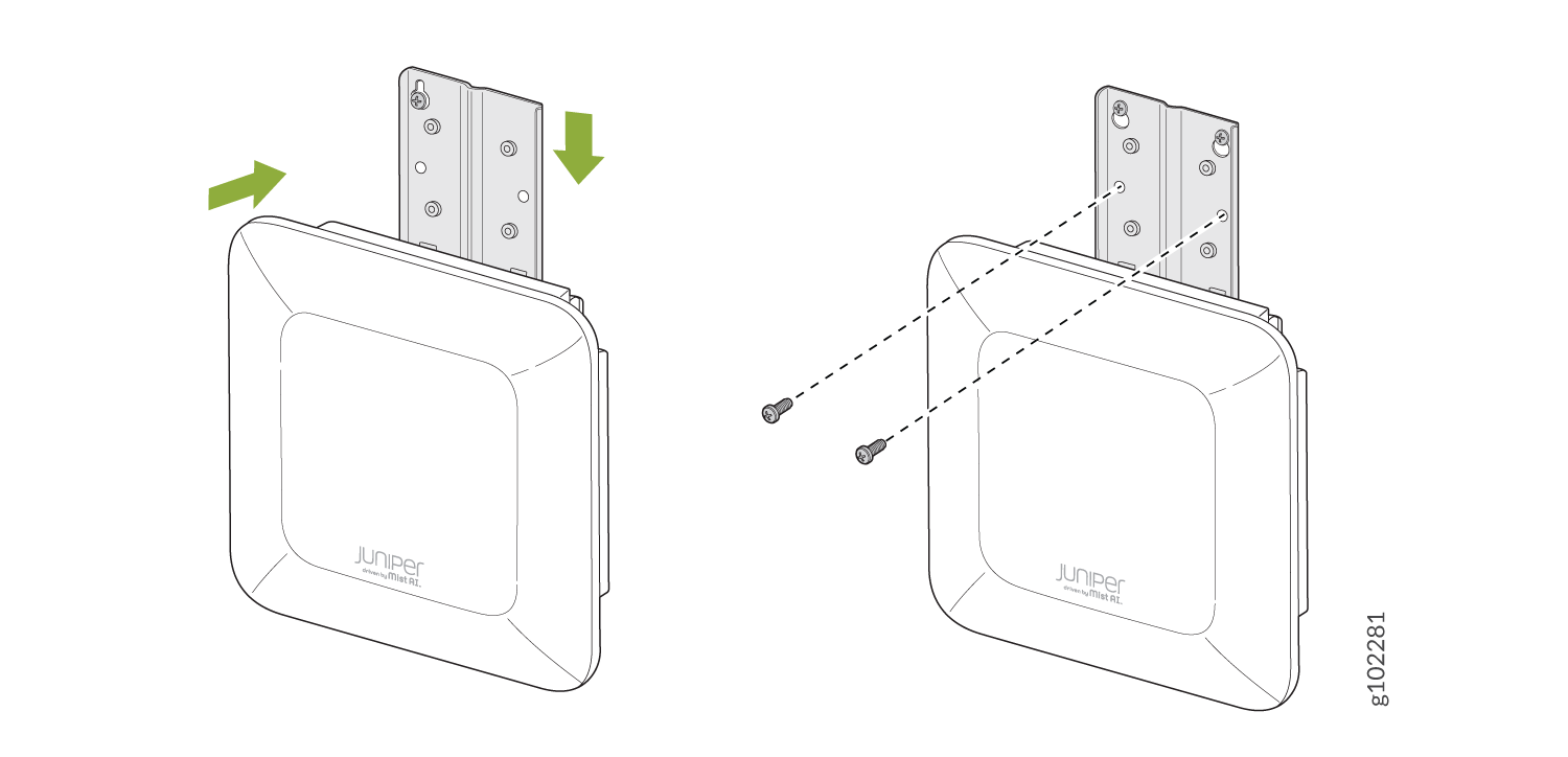
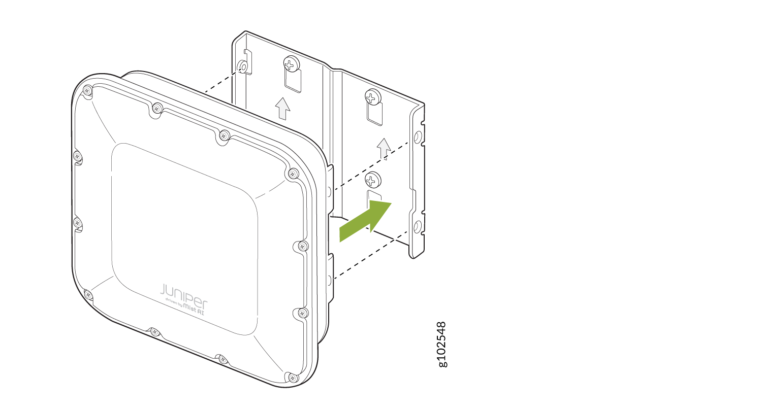
Attach the AP64 to the APOUTBR-FM2 mounting bracket.
Figure 8: Attach the AP64 to the APOUTBR-FM2
-
Secure the AP64 by using the four M6 screws, washers, and lock washers
provided along with the AP.
Figure 9: Mount the AP64 on a Wall (Flush Mount)
Mount the AP64 on a Pole Using APOUTBR-FM2 (Flush Mount)
-
Attach the hose clamps to the APOUTBR-FM2 mounting bracket. Use a
screwdriver to release the hose clamps and then pass the hose clamps through
the slots in the flush mount bracket.
Figure 10: Attach Hose Clamps to the APOUTBR-FM2 Mounting Bracket
-
Secure the APOUTBR-FM2 mounting bracket to the pole. Wind the open end of
the hose clamps around the pole and tighten the hose clamp screws by using a
screwdriver. Tighten the screws until the mounting bracket is secured in
place.
Figure 11: Install the APOUTBR-FM2

-
Attach the AP64 to the APOUTBR-FM2 mounting bracket using the four M6
screws, washers, and lock washers provided along with the AP.
Figure 12: Mount an AP64 on a Pole (Flush Mount)
Mount the AP64 on a Wall (Articulating Mount)
-
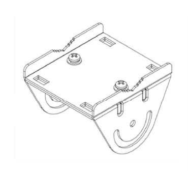
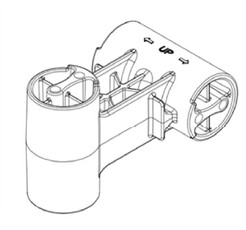
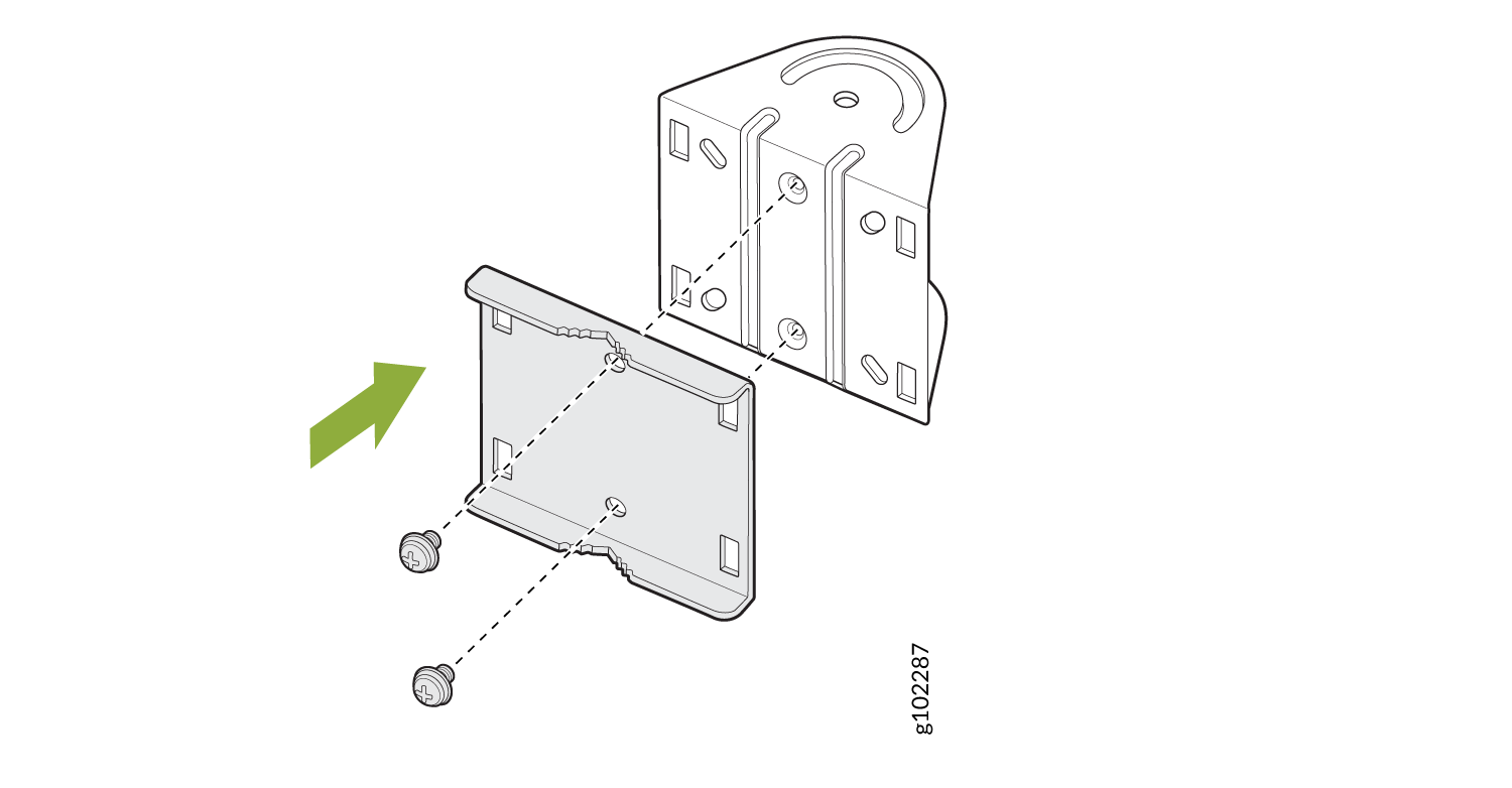
Disassemble the APOUTBR-ART2 mounting bracket 1 by removing the two
screws.
Figure 13: Disassemble the APOUTBR-ART2 Mounting Bracket 1
-
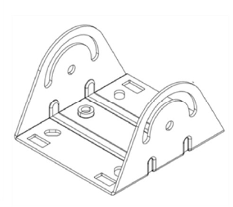
Install the APOUTBR-ART2 mounting bracket 1 on the wall using four
screws.
Figure 14: Install the APOUTBR-ART2 Mounting Bracket 1 on a Wall
-
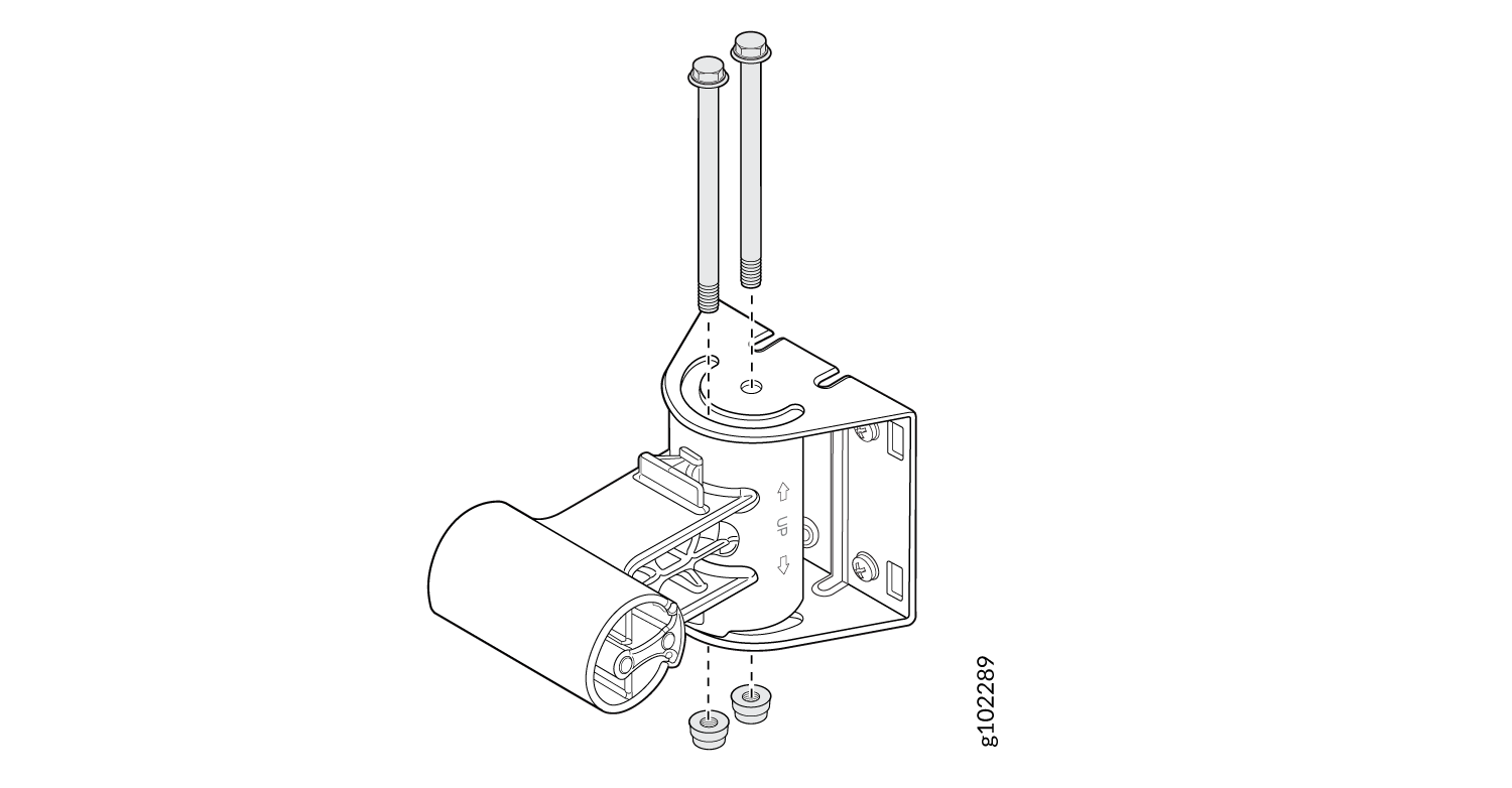
Attach the APOUTBR-ART2 mounting bracket 2 to the mounting bracket 1 by
using two bolts and nuts. Orient the side with "← UP → " as shown in Figure 15.
Figure 15: Attach the APOUTBR-ART2 Mounting Bracket 2 to the Mounting Bracket 1
-
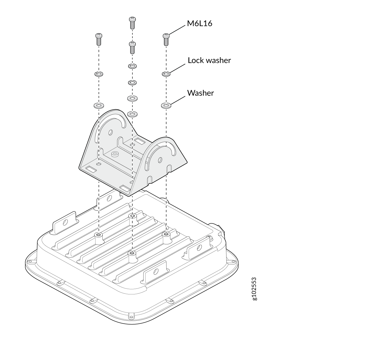
Attach the APOUTBR-ART2 mounting bracket 3 to the AP64 by using the four M6
screws, washers, and lock washers provided along with the AP.
Figure 16: Attach the APOUTBR-ART2 Mounting Bracket 3 to the AP64
-
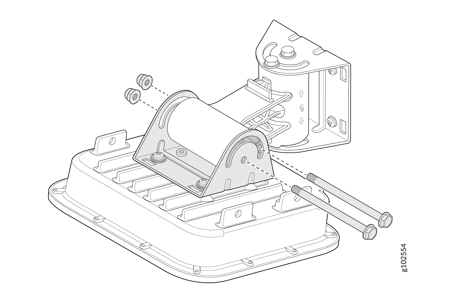
Attach the APOUTBR-ART2 mounting bracket 2 to the mounting bracket 3 by
using two bolts and nuts.
Figure 17: Mount the AP64 on a Wall (Articulating Mount)
Mount the AP64 on a Pole (Articulating Mount)
-
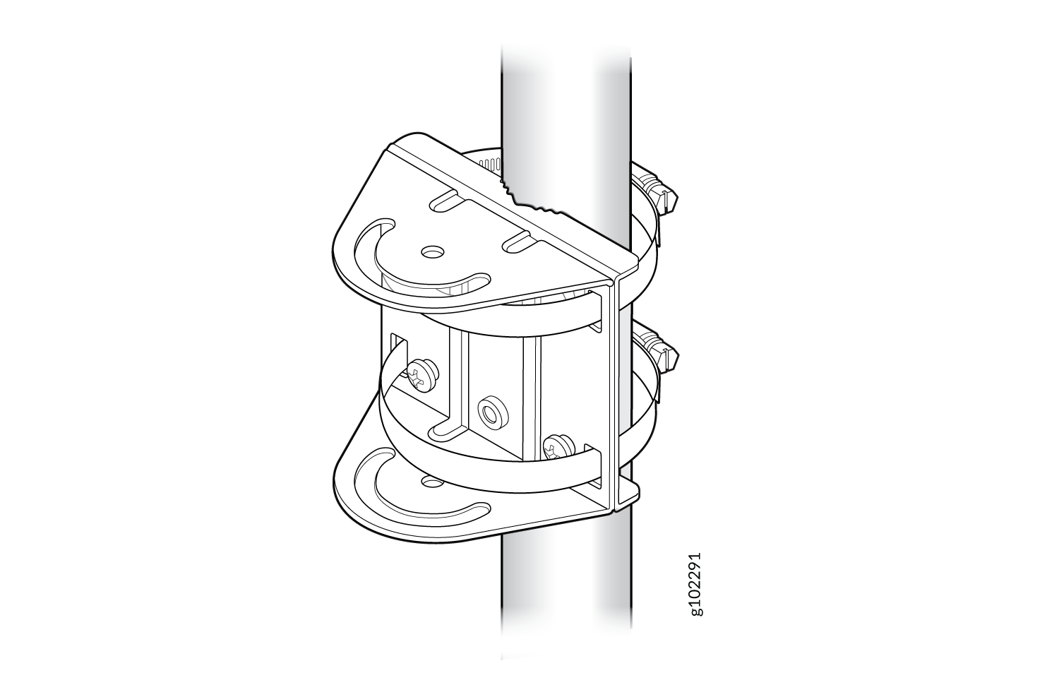
Attach the APOUTBR-ART2 mounting bracket 1 to the pole. Wind the open end
of the hose clamps around the pole and tighten the hose clamp screws by
using a screwdriver. Tighten the screws until the bracket is secured in
place.
Figure 18: Attach the APOUTBR-ART2 Mounting Bracket 1 to a Pole
-
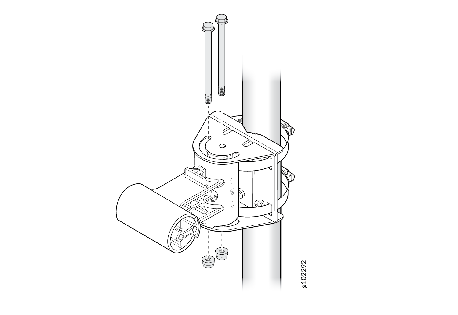
Attach the APOUTBR-ART2 mounting bracket 2 to the mounting bracket 1 by
using two bolts and nuts included in the bracket kit. Orient the side with
the label ← UP → as shown in Figure 19.
Figure 19: Attach the APOUTBR-ART2 Mounting Bracket 2 to the Mounting Bracket 1
-
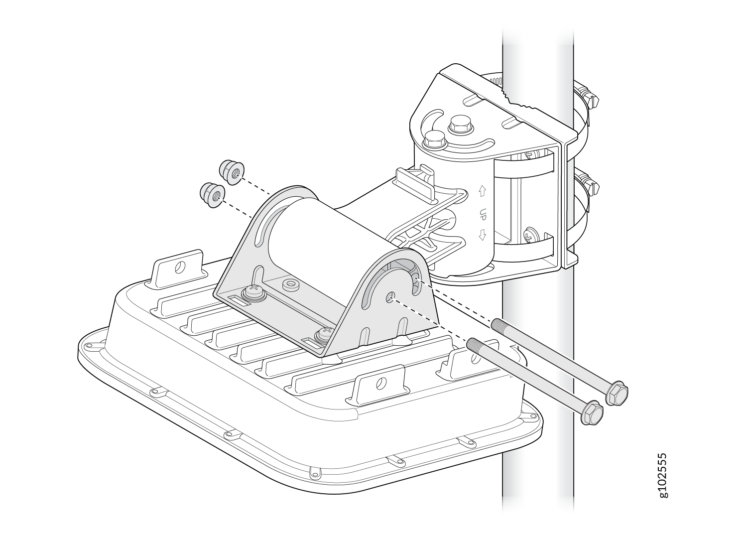
Attach the APOUTBR-ART2 mounting bracket 3 to the AP64 by using the four M6
screws, washers, and lock washers provided along with the AP.
Figure 20: Attach the APOUTBR-ART2 Mounting Bracket 3 to the AP64
-
Attach the APOUTBR-ART2 mounting bracket 2 to the mounting bracket 3 by
using two bolts and nuts.
Figure 21: Mount the AP64 on a Pole (Articulating Mount)
Connect an RJ-45 Cable Gland
-
Disassemble the cable gland:
-
Remove the cable gland nut by turning it counter-clockwise.
-
Remove the blue seal. Ensure that you select the correct seal. The cable gland has two seals—a blue seal (7 mm through 9.5 mm diameter) and a red seal (5.5 mm through 7 mm diameter).
Figure 22: Disassemble an RJ-45 Cable Gland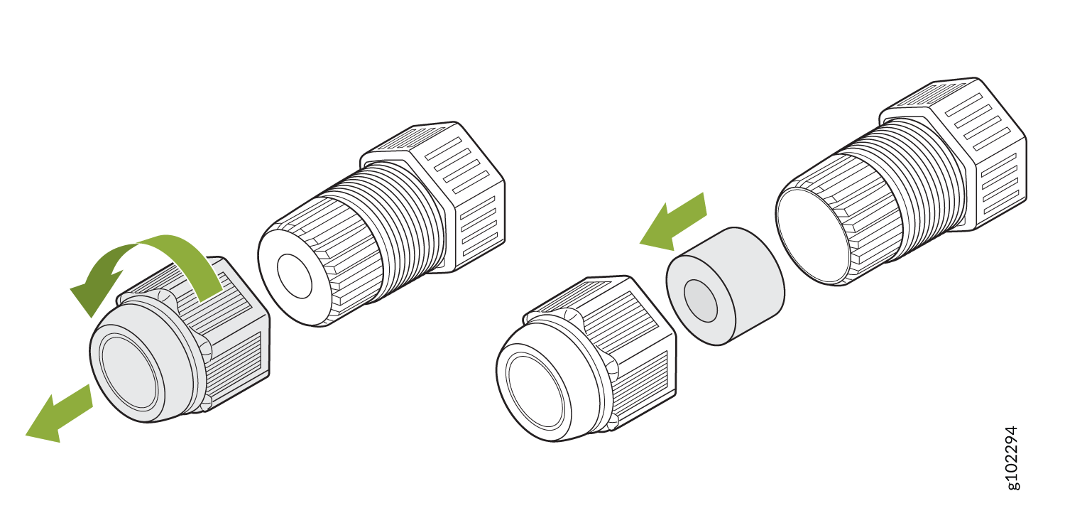
-
-
Insert the RJ-45 cable through the cable gland:
-
Open the seal and insert the RJ-45 cable through the nut and the seal.
Figure 23: Insert the RJ-45 Cable Through the Nut and the Seal of the Cable Gland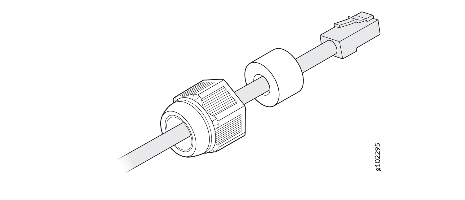
-
Push the RJ-45 cable through the cable gland. Push the seal into the cable gland and loosely tighten the nut.
Figure 24: Push the RJ-45 Cable Through the Cable Gland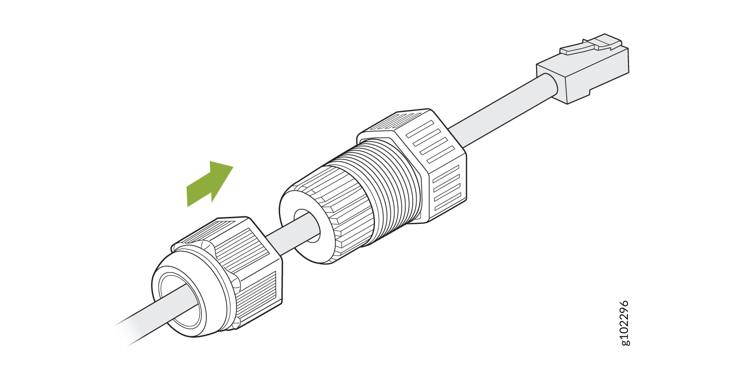
-
-
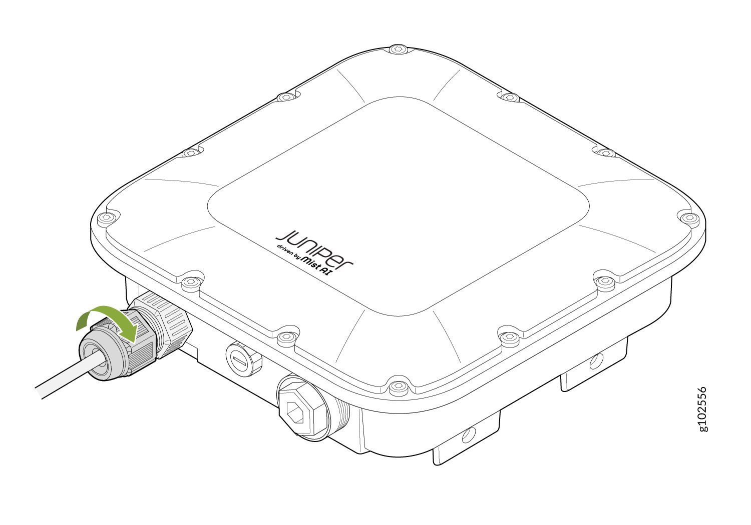
Connect the RJ-45 cable to the AP port. Attach the cable gland to the AP
and tighten it with a torque of 10–12 kg-cm.
Then, fully tighten the
nut to the cable gland with a torque of 7–10 kg-cm.
Figure 25: Attach a Cable Gland to the AP64