AP63 Components and Specifications
| Component | Description |
|---|---|
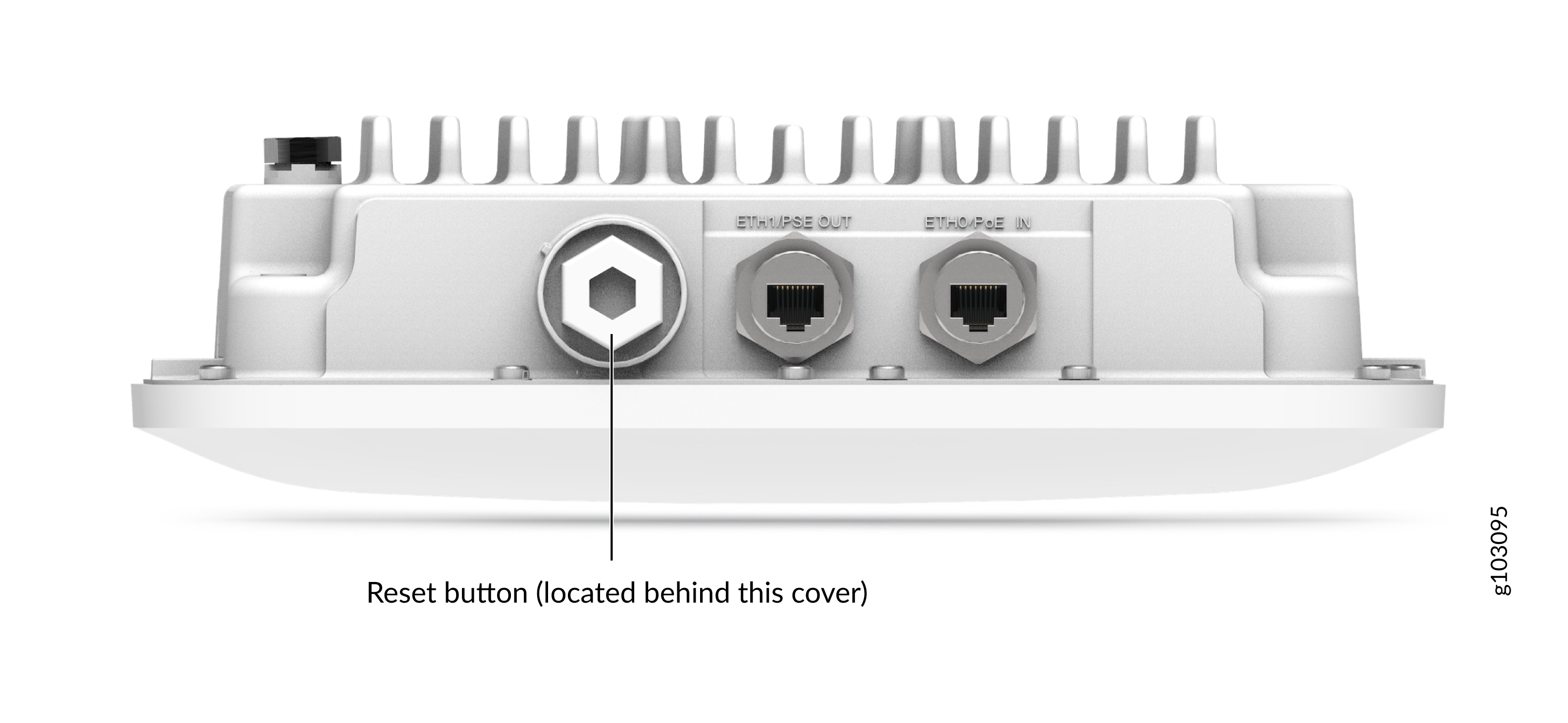
| ETH1/PSE OUT | 10/100/1000BASE-T RJ-45 port + 802.3af PoE power sourcing equipment (PSE) (if PoE In is 802.3bt) |
| ETH0/POE IN | 100/1000/2500BASE-T RJ-45 port that supports an 802.3at-powered or 802.3bt-powered device |
| Reset | Reset button that you can use to reset the AP configuration to the factory default. See Reset an AP to the Factory-Default Configuration. |
| Antenna connectors (available only in AP63E models) | Six N-type connectors (four dual-band for client radios; two dual-band for the third radio) |
| Status LED | A multicolor status LED to indicate the status of the AP and to help troubleshoot issues. See Troubleshoot a Juniper Access Point. |
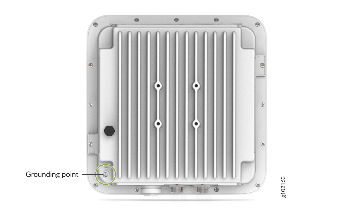
The AP63 also has a grounding point on the rear. Figure 3 shows the location of the grounding point on the AP63.
Figure 3: Rear Panel of AP63
For AP63 specifications, see the AP63 Datasheet.