ACX7509 Power System
The ACX7509 power system includes AC/HDVC power supplies and related power cords and cables, DC power supplies and related cords and cables, and cable lugs. The power supplies operate within specified ranges and are equipped with alarms and indicators.
The ACX7509 router is powered by 3000 W redundant hot-removable and hot-insertable pre-installed AC/high-voltage DC (HDVC) or DC power supplies. ACX7509-BASE configuration(One RCB and one FEB) requires 1 + 1 PSM redundancy and ACX7509-PREMIUM configuration requires 2+2 PSM redundancy. If you choose the ACX7509-BASE configuration, this can be connected to the same source or two separate sources for 1+1 redundancy. When you choose the ACX7509-PREMIUM configuration option, if you have the same power source you would need 2+1 PSM redundancy and if you have two separate power sources, you would need 2+2 PSM redundancy. If any power supply unit fails, you can replace it without powering off or disrupting the routing function, the other power supply units will balance the electrical load without interruption. Each power supply unit has two outputs: 12 V and 12 V standby. Two counter-rotating fans in each power supply unit provide front to back cooling.
The input voltages are as follows:
-
AC input voltage range: 200–277 V/50–60 Hz, 20A current
-
HVDC input voltage range: 240–280 V, 20A current
-
DC input voltage range: 40 volts direct current (VDC) Min, 72 VDC maximum, 80A current
Do not mix AC/HDVC and DC power supplies in the same chassis.
AC PSMs do not support AC low line of 110V.
BASE configuration routers are shipped with blank panels installed over the two empty power supply slots.
ACX7509 AC/HVDC Power Supply Description
The input power to the AC/HVDC power supplies can be AC power or HVDC power. The power supplies automatically detect AC or HVDC input voltage and manage the power accordingly. AC power can be 180–305 volts alternating current (VAC) input voltage and HVDC power can be 190–400 VDC input voltage. Each 3000- W AC/HVDC PSM has a single AC or HVDC input and provides 12 V power to the system. Figure 1 shows the AC/HVDC power supply.
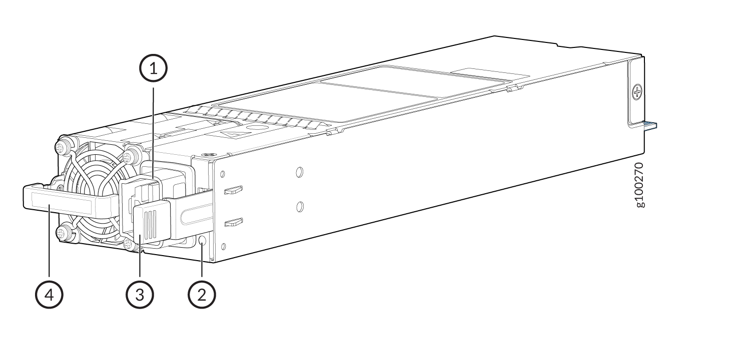
1 — Power plug connector | 3 — Ejector lever |
2 — Status LED | 4 — Orange handle |
- ACX7509 AC/HVDC Power Specifications
- ACX7509 AC/HVDC Power Supply LED
- ACX7509 AC/HVDC Power Cord Specifications
ACX7509 AC/HVDC Power Specifications
The ACX7509 operates within the AC/HVDC input voltage range listed in Table 1.
| Parameter | Minimum | Rated | Maximum |
|---|---|---|---|
|
Input voltage (AC) |
180 VAC |
200–277 VAC |
305 VAC |
|
Input voltage (HVDC) |
190 VAC |
240–380 VDC |
400 VDC |
|
AC input line frequency |
47 Hz |
50–60 Hz |
63 Hz |
ACX7509 AC/HVDC Power Supply LED
Each ACX7509 AC/HVDC PSM has a status LED on the module faceplate. See Figure 2.
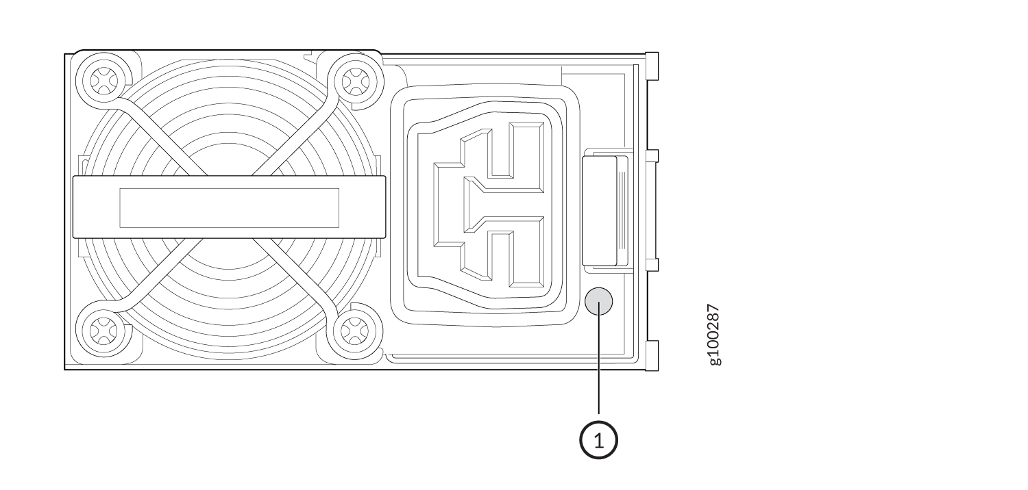
1 — Power supply LED |
The ACX7509 router AC/HVDC PSM uses an amber and green bi–color LED to indicate the operating state. See Table 2.
| PSM State | Green LED | Amber LED |
|---|---|---|
|
The PSM is on and operating properly. |
On |
Off |
|
One or both power supplies lack AC power. |
Off |
Off |
|
The PSM shut down due to a critical event such as high temperature, high power, high current, or fan failure. |
Off |
On |
|
The PSM is operating but indicates a warning event such as high temperature (inlet temperature greater than 53 degrees or a hot spot temperature greater than 95 degrees), high power, high current, or slow fan (less than 1200 rpm). |
Off |
Blinking |
|
The PSM output disabled by system software or other PSM in chassis on with 12VSB (vestigial sideband). |
Blinking |
Off |
|
The AC power cord is unplugged. |
Off |
On |
You can get additional information about the status of the PSMs using the show chassis power command and the show chassis power detail command.
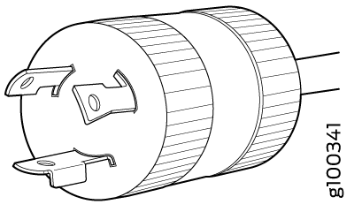
ACX7509 AC/HVDC Power Cord Specifications
Detachable AC power cords are shipped with the AC power supplies. The plug end of the power cord fits into the power source outlet that is standard for your geographical location.
In North America, AC power cords must not exceed 14.75 feet (approximately 4.5 meters) in length, to comply with National Electrical Code (NEC) Sections 400-8 (NFPA 75, 5-2.2) and 210-52 and Canadian Electrical Code (CEC) Section 4-010(3). The cords that you can order for the ACX7509 router comply with those codes.
Table 3 provides right-angle power cord specifications for specific country or region. You can install this cable in the ACX7509 router that is installed in a rack with limited space.
| Locale | Cord Set Rating | Plug Standards | Spare Juniper Model Number |
|---|---|---|---|
|
Japan |
20 A, 250 VAC |
L6-20 |
CBL-JNP-SDG4-JPL |
|
Taiwan |
20 A, 250 VAC |
L6-20 |
CBL-JNP-SDG4-TW |
|
USA |
30 A, 250 VAC |
L6-30 |
CBL-JNP-SDG4-US-L6 |
|
Europe |
25 A, 300 VAC (cable) |
332P6S |
CBL-JNP-PWR-EU |
|
USA |
30 A, 277 VAC |
L7-30 |
CBL-JNP-SDG4-US-L7 |
|
India |
20 A, 250 VAC (cable) |
332P6S |
CBL-JNP-SDG4-IN |
|
South Korea |
25 A, 250 VAC (cable) |
332P6S |
CBL-JNP-SDG4-SK |
When you install a right-angle power cord on a ACX7509 router, the chassis depth is 800 mm including the cable bend radius and 850 mm when you install the straight power cord.
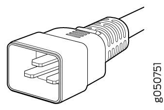
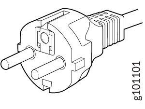
Table 4 provides AC power cord (straight) specifications for each country or region.
| Locale | Cord Set Rating | Plug Standards | Spare Juniper Model Number | Graphic |
|---|---|---|---|---|
|
Argentina |
16 A, 250 VAC |
IRAM 2073 Type RA/3 |
CBL-JNP-SG4-AR |
|
|
Australia and UK |
16 A, 250 VAC |
IEC 60309 |
CBL-JNP-SG4-316P6W |
|
|
Brazil |
16 A, 250 VAC |
NBR 14136 Type BR/3 |
CBL-JNP-SG4-BR |
|
|
China |
16 A, 250 VAC |
GB2099-1 |
CBL-JNP-SG4-CH |
|
|
China and Japan |
16 A, 250 VAC |
C20 to Anderson 3-5958p4 |
CBL-JNP-SG4-C20-CH |
|
|
Europe (except Italy, Switzerland, and the United Kingdom) |
16 A, 250 VAC |
CEE 7/7 STRAIGHT |
CBL-JNP-SG4-EU |
|
|
India/SA |
16 A, 250 VAC |
SANS 164/1 |
CBL-JNP-SG4-SA |
|
|
Israel |
16 A, 250 VAC |
SI 32/1971 Type IL/3G |
CBL-JNP-SG4-IL |
|
|
Italy |
16 A, 250 VAC |
CEI 23-16 |
CBL-JNP-SG4-IT |
|
|
Japan |
20 A, 250 VAC |
L6-20 |
CBL-JNP-SGD4-JPL |
|
|
North America |
20 A, 250 VAC |
C20 to Anderson 3-5958p4 |
CBL-JNP-SG4-C20 |
|
|
North America |
20 A, 250 VAC |
Locking NEMA L6-20P |
CBL-JNP-SG4-US-L |
|
|
North America |
16 A, 250 VAC |
NEMA 6-20P |
CBL-JNP-SG4-US |
|
|
North America |
20 A, 277 VAC |
NEMA I7-20P |
CBL-JNP-SG4-HVAC |
|
|
Central Europe |
16 A, 250 VAC |
SEV1011 |
CBL-JNP-SG4-SZ |
|
|
USA |
20 A, 250 VAC |
IEC 320 P6 |
CBL-JNP-SG4-320P6W |
You must provide 16 A circuit breaker to the 16 A power cord connected to AC mains of each power supply.
| Cable | Cord Set Rating | Spare Juniper Model Number |
|---|---|---|
| HVDC power cord | 30 A, 400 VDC (Open ended power cord) | CBL-PWR2-BARE |
The insulation color for wires in the HVDC cables are color coded. Green is ground, black is line, and white is neutral. For HVDC, the black and white wires are not polarity-sensitive. The black wire can be positive (+) or neutral (–), and the white wire can be positive (+) or negative (–).
ACX7509 DC Power Supply Description
The ACX7509 DC power supplies are hot-removable and hot-insertable field-replaceable units (FRUs). Each 3000 W PSM has a single DC input and provides 12 VDC output with a standby voltage of 12 VDC. The ACX7509 DC power supplies can operate with an input current of 80 A or 60 A.
Do not mix AC/HVDC and DC power supplies in the same chassis.
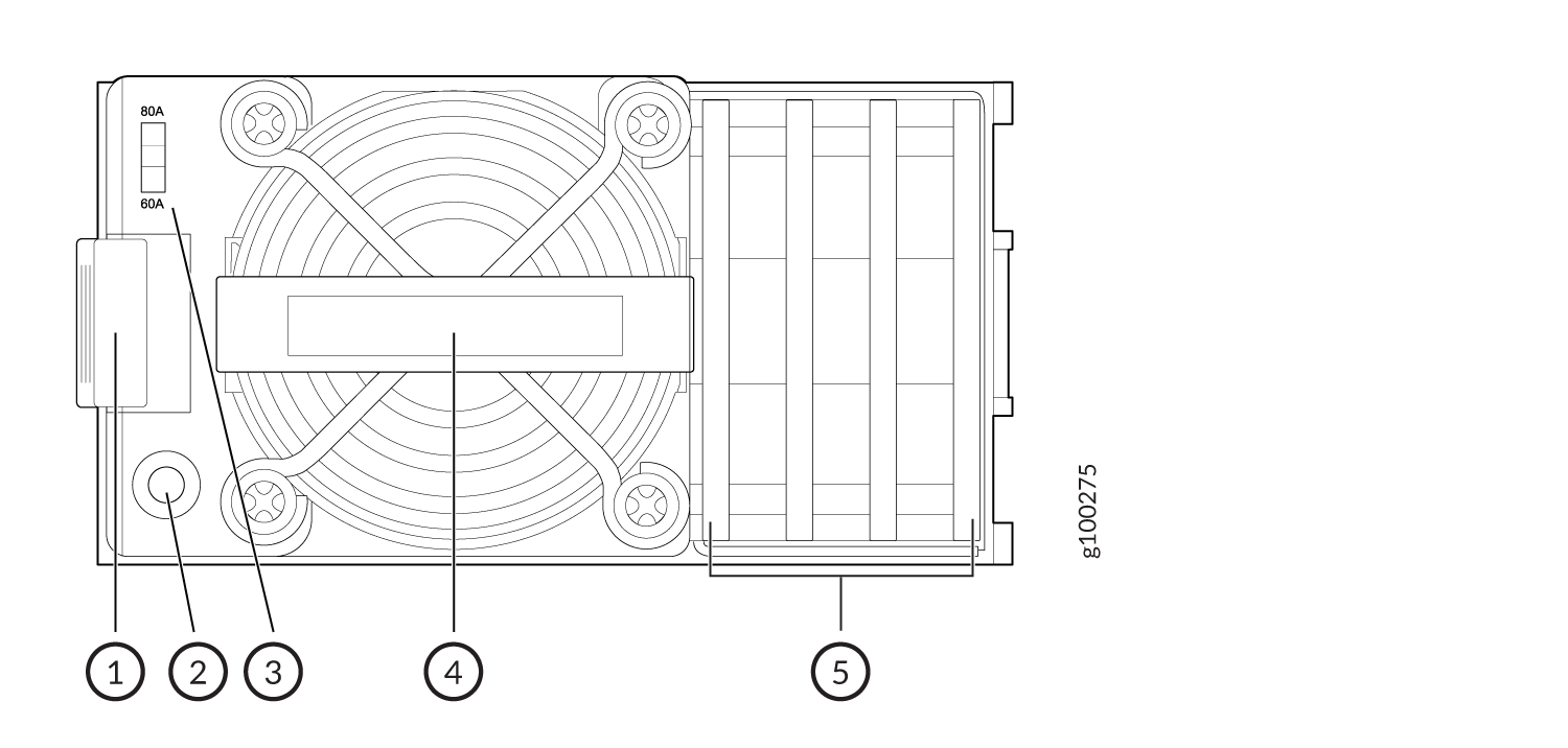
1 — Ejector lever | 4 — Handle |
2 — Status LED | 5 — Terminal block cover |
3 — DC input current selector (DIP switch) |
- ACX7509 DC Power Supply LED
- ACX7509 DC Input Current Selector
- ACX7509 Input DC Voltage Specification
- 60 A Input Feed Power Management
- ACX7509 DC Power Cables
- ACX7509 DC Power Cable Lugs
ACX7509 DC Power Supply LED
Each ACX7509 DC PSM has a status LED on the PSM faceplate. See Figure 4.
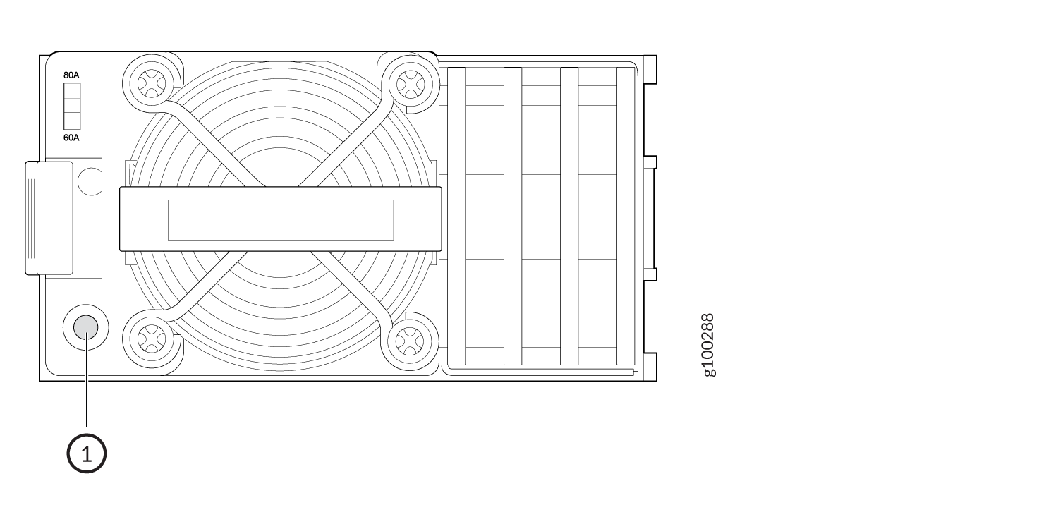
1 — Power supply status LED |
Use Table 6 to interpret the state of the PSM status LED.
|
LED Color |
Power Supply State |
|---|---|
|
Off |
The power supplies do not have DC power |
|
Solid green |
The PSM is on and in the OK state |
|
Blinking green |
The PSM output disabled by system software or other PSU in chassis ON with 12VSB. |
|
Solid amber |
The DC power cord is unplugged, but the second PSM still has DC power. |
|
Blinking amber |
The PSM is operating, but there are warning events. Possible causes include high temperature, high power, high current, or a slow fan. |
You can get additional information about the status of the PSMs using the show chassis power command and show chassis power detail command.
ACX7509 DC Input Current Selector
The ACX7509 DC PSM can operate with an input current of 80 A or 60 A. You select the input rating by moving the DC input current selector (DIP switch) to the desired setting. If you select 60 A, the PSM limits the output power so that the input current does not exceed 60 A under normal steady-state operation. If you select 80 A, the PSM limits the output power so that the input current does not exceed 80 A.
For example:
|
If you select... |
Then... |
|---|---|
|
60 A |
The PSM limits the output power to 2200 W when the input voltage is between 40V and 48V. It linearly increases the output power if the input voltage increases. The PSM provides 2700 W output power when the input voltage is between 48V and 72V. |
|
80 A |
The PSM provides 3000 W output power throughout the input voltage range from 40 VDC to 72 VDC. |
ACX7509 Input DC Voltage Specification
The ACX7509 DC PSMs operate within the DC input voltage range listed in Table 7.
Depending on the available input source, Juniper recommends that the 48-VDC facility DC source be equipped with a 2 pole circuit breaker rated at a minimum of 60 A (48 VDC) or 80 A (48 VDC) based on DIP switch current setting, or as required by local code.
|
Input Switch Setting |
Minimum Input DC Voltage |
Rated Input DC Voltage |
Maximum Input DC Voltage |
Maximum Input DC Current |
Maximum Output Power |
|---|---|---|---|---|---|
|
60 A |
40 VDC |
48 VDC to 60 VDC |
72 VDC |
60 ADC |
2700 W |
|
80 A |
40 VDC |
48 VDC to 60 VDC |
72 VDC |
90 ADC |
3000 W |
60 A Input Feed Power Management
The 60 A DC PSM capacity changes when the input voltage is below or above the under-voltage limit, as follows:
-
When the 60 A DC PSM input voltage is above the input under-voltage warning limit, its capacity is 2700 W.
-
When the input voltage is below the input under-voltage warning limit, the PSM capacity is reduced to 2200 W.
When the input voltage is above the input under-voltage warning limit, the software adjusts the system capacity and reallocates power to the FRUs based on the new system capacity.
ACX7509 DC Power Cables
You must supply DC power cables that meet the specifications required by the local code, laws, and standards. The wire insulation is color coded. Green is ground, black is line, and white is neutral. The wires are labeled (+) and (–) to indicate their polarity.
You must ensure that power connections maintain the proper polarity.
For field-wiring connections, use copper conductors only.
Make sure that DC power cables do not block access to ACX7509 components or lie on the ground where people can trip on them.
ACX7509 DC Power Cable Lugs
The accessory box shipped with the ACX7509 router includes the cable lugs that attach to the terminal studs of each PSM. (The cable lug shown in Figure 5 is also used for grounding the chassis.) The cable lugs are dual hole and sized to fit 1/4-20 UNC terminal studs at 15.86-mm (0.625-in.) center line.
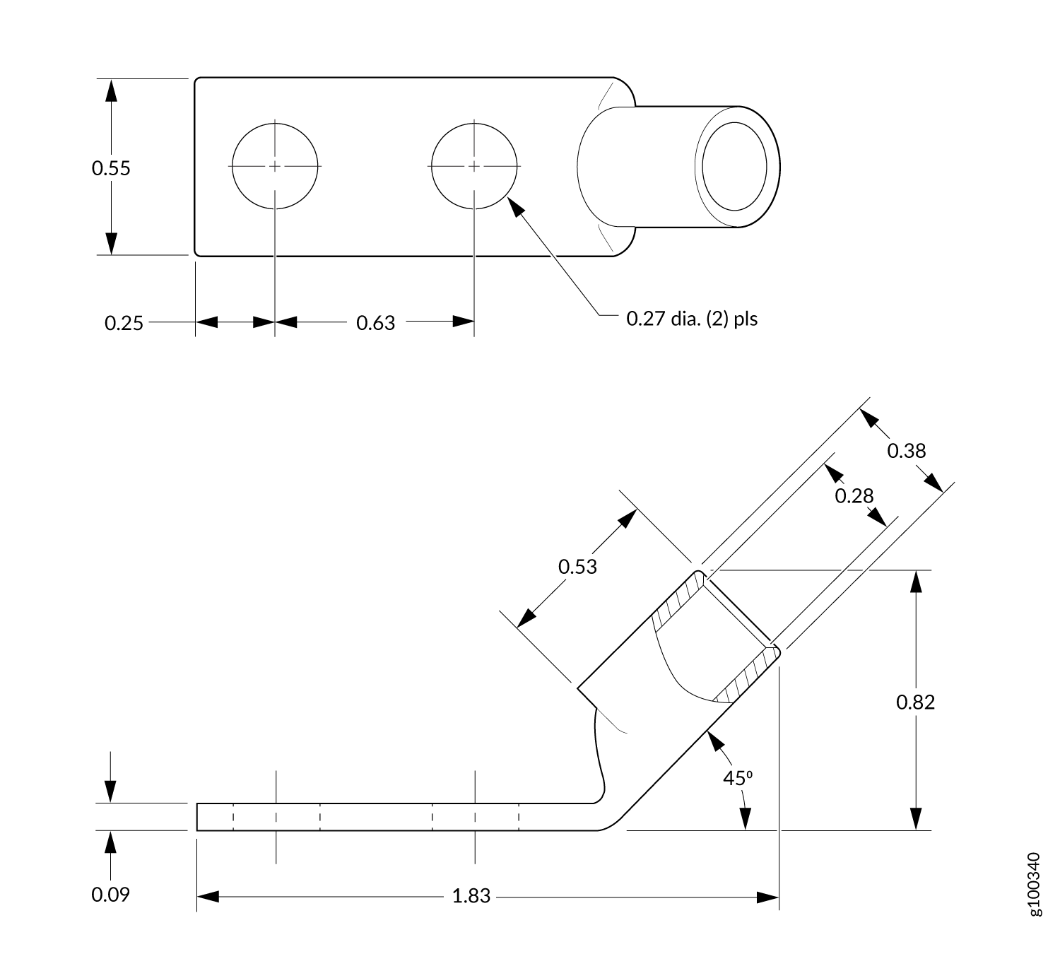
Before you begin to install the ACX7509 router, have a licensed electrician attach a cable lug to the power cables that you supply. A cable with an incorrectly attached lug can damage the ACX7509 router.