ACX7509 Routing and Control Board Maintenance
Maintaining an ACX7509 router includes removing and installing the Routing and Control board.
The ACX7509 router is shipped with one or two Routing and Control Boards (RCBs) preinstalled in the chassis, depending on the configuration. You can install RCBs in the two top slots on the front of the chassis.
When you power on a router with a single RCB preinstalled in it, the RCB comes online as the primary RCB. The primary RCB powers on the Forwarding Engine Boards (FEBs) and the Flexible PIC Concentrator (FPC). If you install the second RCB, it powers up and the Routine Engine comes online in the backup mode.
When you power on a router for the first time with two RCBs installed, the RCB installed in slot 0 comes online as the primary RCB and powers on the FEBs and the FPCs. The RCB installed in slot 1 comes online as the backup RCB by default. You can change this configuration by using the CLI.
To remove or install an RCB, read the following sections.
Remove the Routing and Control Board from the ACX7509 Router
In redundant configurations, the Routing and Control Board (RCB) in an ACX7509 router is a hot-removable and hot-insertable field-replaceable unit (FRU). In base configurations, you need to install a second RCB before removing a failing RCB, to prevent the router from shutting down. We recommend that you take base system offline before replacing the RCB.
Before you remove an RCB, ensure that you have an electrostatic discharge (ESD) grounding strap.
In base configurations, removal of the RCB causes the system to shut down. In redundant configurations, removal of the RCB causes the system to reboot and start the election process for a new primary RCB.
To remove an RCB:
-
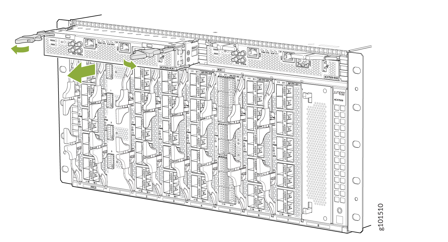
Grasp both ejector handles, spread them apart, and slide the RCB about
halfway out of the chassis (see Figure 1).
Figure 1: Removing an RCB from the ACX7509 Router
Install the Routing and Control Board in the ACX7509 Router
In redundant configurations, the Routing and Control Board (RCB) in an ACX7509 router is a hot-removable and hot-insertable field-replaceable unit (FRU). In base configurations, you need to install a second RCB before removing a failing RCB, to prevent the router from shutting down.
Before you install an RCB, ensure that you have an electrostatic discharge (ESD) grounding strap.
To install an RCB:
-
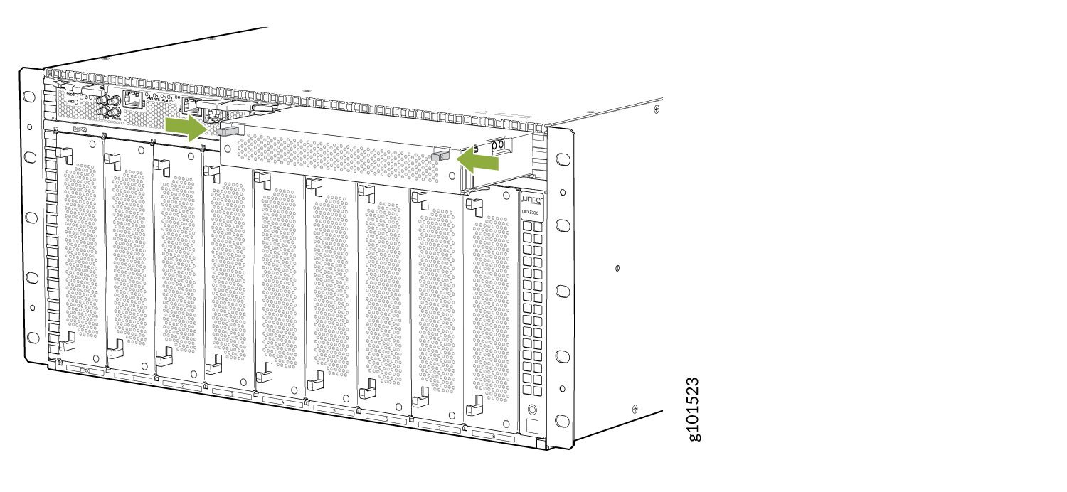
If an RCB blank (JNP5K-RCB-BLNK) is installed, press the handles on the
blank and gently pull out the blank from the slot (see Figure 2) or in redundant configurations remove the failing RCB
(see Remove the Routing and Control Board from the ACX7509 Router).
Figure 2: Removing the RCB Blank
-
Grasp the two ejector handles, and fold them inward until they latch to
seat the RCB (see Figure 3).
Figure 3: Installing an RCB
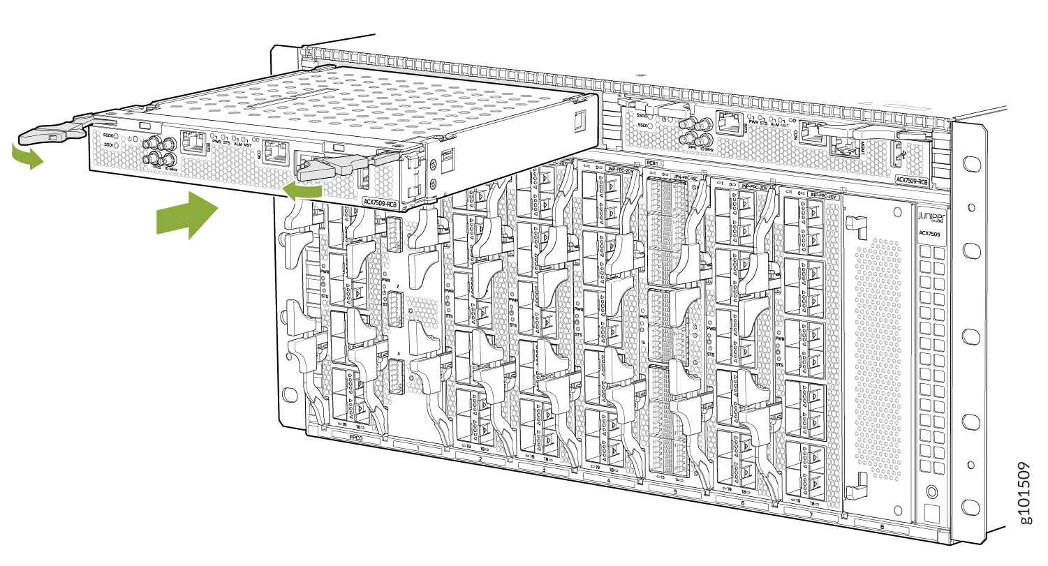
The RCB begins the power-on sequence when fully seated.