ACX7509 Cable Management System Maintenance
Maintaining an ACX7509 router includes installing and removing the cable management system properly.
The ACX7509 cable management system organizes and protects optical cabling attached to the Routing and Control Boards (RCBs) and Flexible PIC Concentrator (FPC).
The cable management system consists of the following components:
-
Left and right side covers
-
Fiber management tray
-
Cable manager door
-
Air filter door
Install the ACX7509 Cable Management System
Ensure that you have the following parts and tools available to install the ACX7509 cable management system:
-
Phillips (+) screwdriver, number 2
-
Eight mounting screws (provided)
-
Electrostatic discharge (ESD) grounding strap to wrap around your bare wrist and connect to an ESD point on the chassis
To install the cable management system:
-
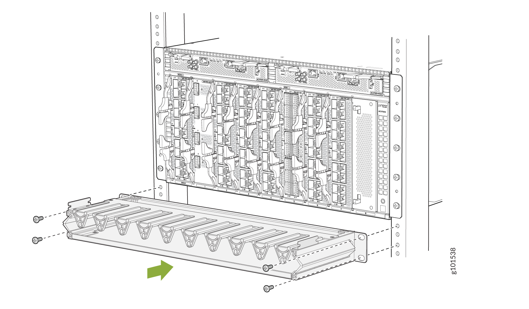
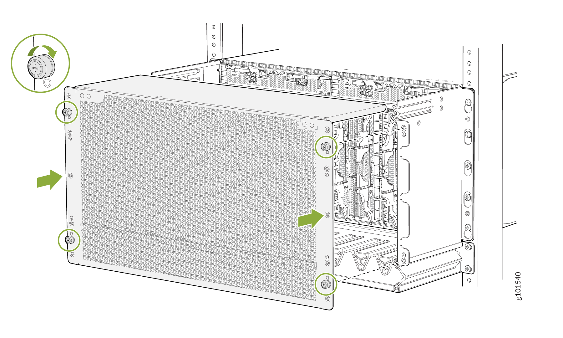
Install mounting screws into each of the mounting bracket holes aligned
with the rack, starting from the bottom, and tighten the screws. See Figure 1.
Figure 1: Installing Fiber Management Tray
-
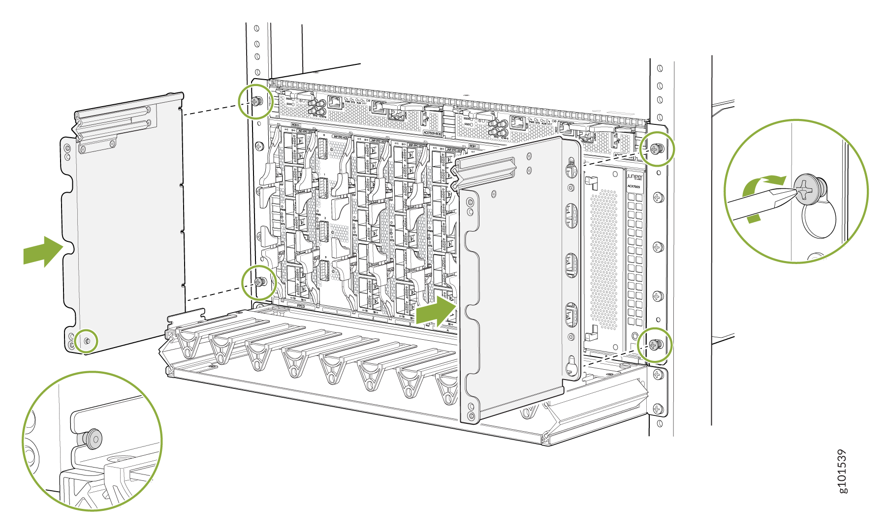
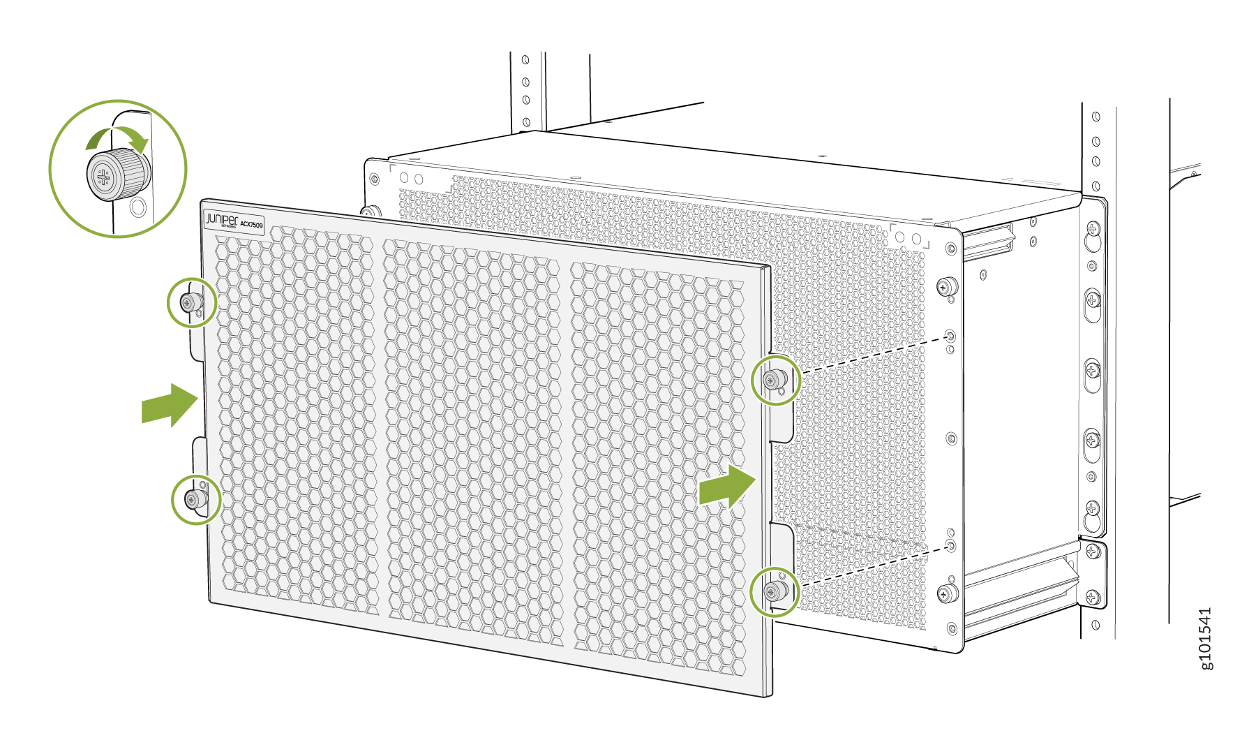
Install back the top and bottom chassis mounting screws and tighten the
screws. See Figure 2.
Figure 2: Installing the Left and Right Side Covers
-
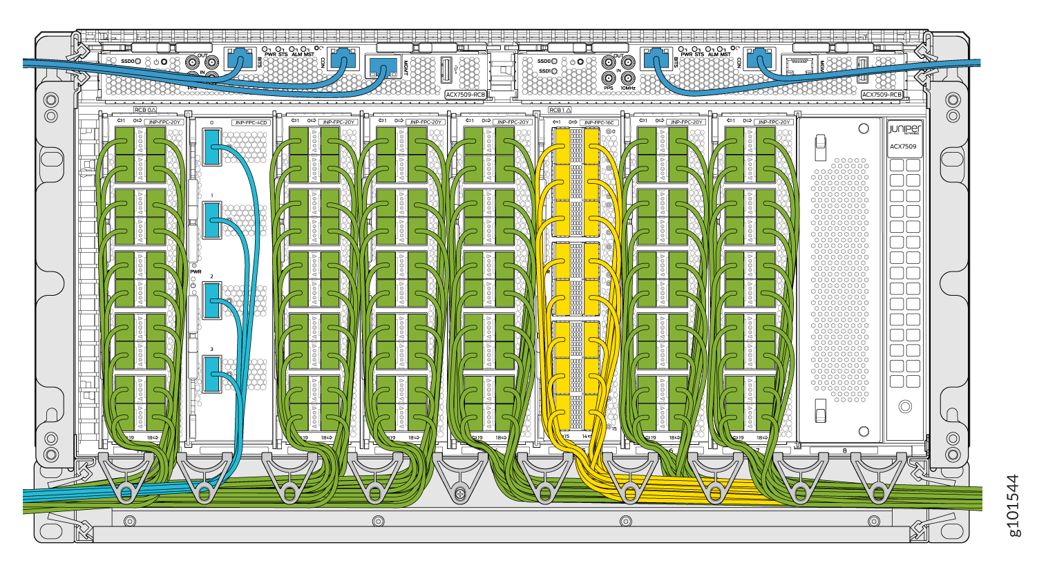
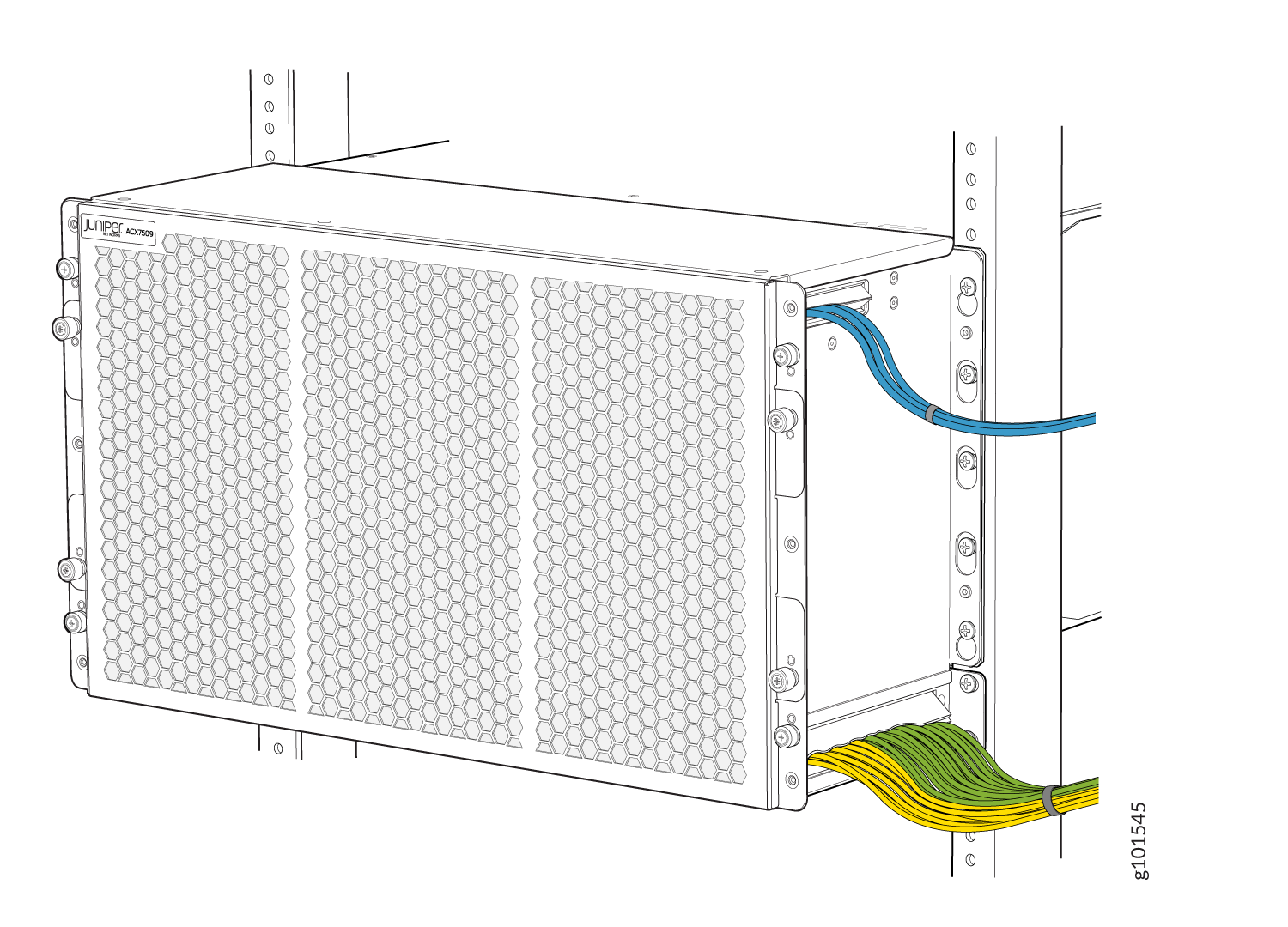
Arrange the FPC cables in the fiber management tray and the cables from the
RCBs in the left and right side covers. See Figure 3.
Figure 3: Cables Arranged in the Fiber Management Tray and Left and Right Side Covers
-
Slide the top cover of the cable manager door into the left and right side
covers, and tighten the four captive screws. See Figure 4.
Figure 4: Installing the Cable Manager Door
-
Mount the air filter door onto the cable manager door, and tighten the four
captive screws. See Figure 5.
Figure 5: Installing the Air Filter Door
Cable Management System Installed on ACX7509 router.
Remove the ACX7509 Cable Management System
Ensure that you have the following parts and tools available to remove the ACX7509 cable management system:
-
Phillips (+) screwdriver, number 2
-
Antistatic bag or an antistatic mat
-
Electrostatic discharge (ESD) grounding strap to wrap around your bare wrist and connect to an ESD point on the chassis
To remove the cable management system:
-
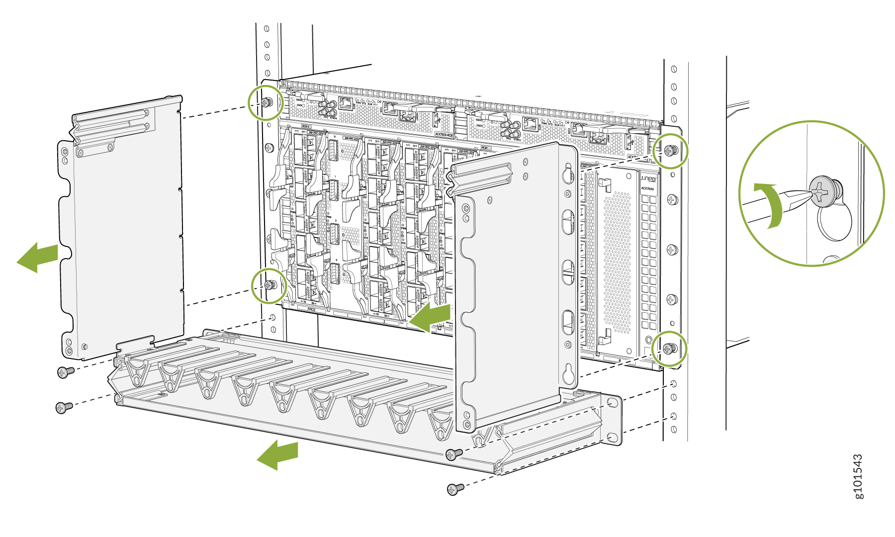
Loosen the four top and bottom captive screws, and pull the cable manager
door out of the right and left side covers. See Figure 6.
Figure 6: Removing the Cable Manager Door
-
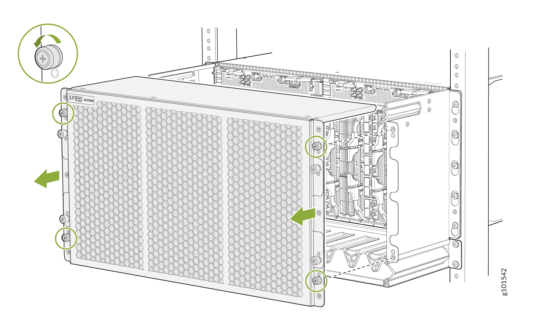
Loosen the four mounting screws securing the fiber management tray to the
rack rails, and remove the fiber management tray. See Figure 7.
Figure 7: Removing the Left and Right Side Covers and Fiber Management Tray