Connect Power to the ACX7509 Router
Connecting the correct power current to the ACX7509 router involves numerous steps and safety precautions to prevent equipment damage and personal injury.
To meet safety and electromagnetic interference (EMI) requirements and to ensure proper operation, you must connect the ACX7509 router to an earth ground before you connect it to power.
Do not mix AC and DC power supplies in the same chassis.
Connect AC Power to an ACX7509 Router
The AC power supply modules (PSMs) in an ACX7509 router are hot-removable and hot-insertable field-replaceable units (FRUs). You can remove and replace the PSMs without powering off the router or disrupting routing functions.
Before you begin to connect AC power to the router:
-
Ensure that you have connected the router chassis to an earth ground.
CAUTION:Before you connect power to the router, a licensed electrician must attach a cable lug to the grounding and power cables that you supply. A cable with an incorrectly attached lug can damage the router (for example, by causing a short circuit).
To meet safety and electromagnetic interference (EMI) requirements and to ensure proper operation, you must connect the chassis to an earth ground before you connect it to power. For installations that require a separate grounding conductor to the chassis, use the protective earthing terminal on the router chassis to connect to the earth ground. The router gains additional grounding when you plug the PSM in the router to a grounded AC power outlet by using the AC power cord appropriate for your geographical location.
-
Ensure that you have a power cord appropriate for your geographical location available to connect AC power to the router.
-
Read General Electrical Safety Guidelines and Warnings and Action to Take After an Electrical Accident .
-
Ensure that you have taken the necessary precautions to prevent electrostatic discharge (ESD) damage (see Prevention of Electrostatic Discharge Damage).
-
Ensure that you have an ESD grounding strap.
-
If not already installed, install the power supplies in the router.
Each power supply must be connected to a dedicated power source outlet.
To connect AC power to a ACX7509 router:
-
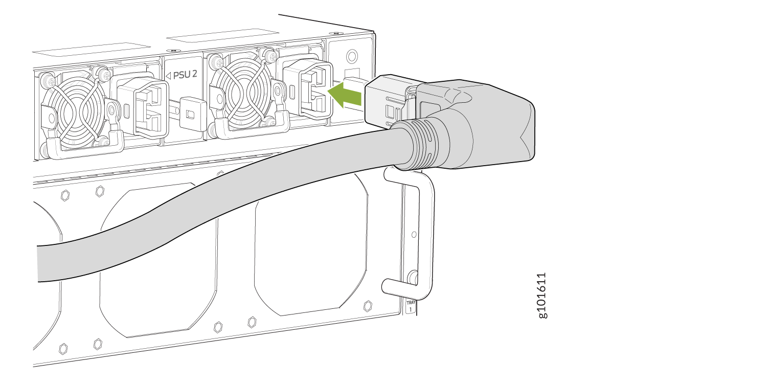
Insert the coupler end of the power cord into the AC power cord inlet on
the AC power supply faceplate (see Figure 1).
Figure 1: Connecting an AC Power Cord
Connect DC Power to the ACX7509 Router
The DC power supply modules (PSMs) in an ACX7509 router are hot-removable and hot-insertable field-replaceable units (FRUs). You can remove and replace the DC PSMs without powering off the router or disrupting routing functions.
DC-powered ACX7509 routers are intended for installation only in a restricted-access location.
The battery return of the DC power supply must be connected as an isolated DC return (DC-I).
Before you begin to connect DC power to the ACX7509 router:
-
Ensure that you have connected the ACX7509 router chassis to an earth ground.
CAUTION:Before you connect power to the router, a licensed electrician must attach a cable lug to the grounding and power cables that you supply. A cable with an incorrectly attached lug can damage the router (for example, by causing a short circuit). See Connect Earth Ground to ACX7509 Routers.
Note:To meet safety and electromagnetic interference (EMI) requirements and to ensure proper operation, you must connect the chassis to an earth ground before you connect it to power. For installations that require a separate grounding conductor to the chassis, use the protective earthing terminal on the ACX7509 router chassis to connect to the earth ground (Connect Earth Ground to ACX7509 Routers).
-
Read General Electrical Safety Guidelines and Warnings and Action to Take After an Electrical Accident and the following DC power warnings:
-
Ensure that you have taken the necessary precautions to prevent electrostatic discharge (ESD) damage (see Prevention of Electrostatic Discharge Damage).
-
Ensure that you have an ESD grounding strap.
-
If not already installed, install the DC power supplies in the router.
-
Ensure that you have the following parts and tools available:
-
Phillips (+) screwdriver, 1/4-in, with a torque range between 6 lb-in (0.68 Nm) and 7 lb-in (0.79 Nm) (not provided)
CAUTION:You must use an appropriate torque-controlled tool to tighten the hex-nuts on the DC power cable connector. Do not over-tighten the hex-nuts. Applying excessive torque damages the terminal block and the wiring tray.
-
Power cable or cables appropriate for your geographical location to connect DC power to the ACX7509 router. We recommend that you use a 4 AWG gauge DC power cable such as a Panduit/LCDX4-14AH-L. The cable lugs are provided with the power supplies.
-
Each power supply unit must be connected to a dedicated power source outlet.
To connect DC power to an ACX7509 router:
-
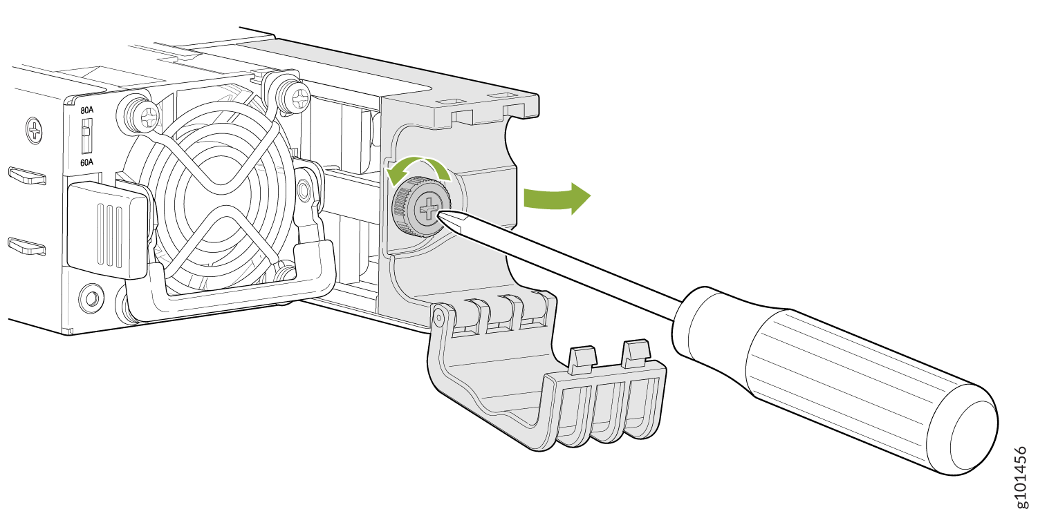
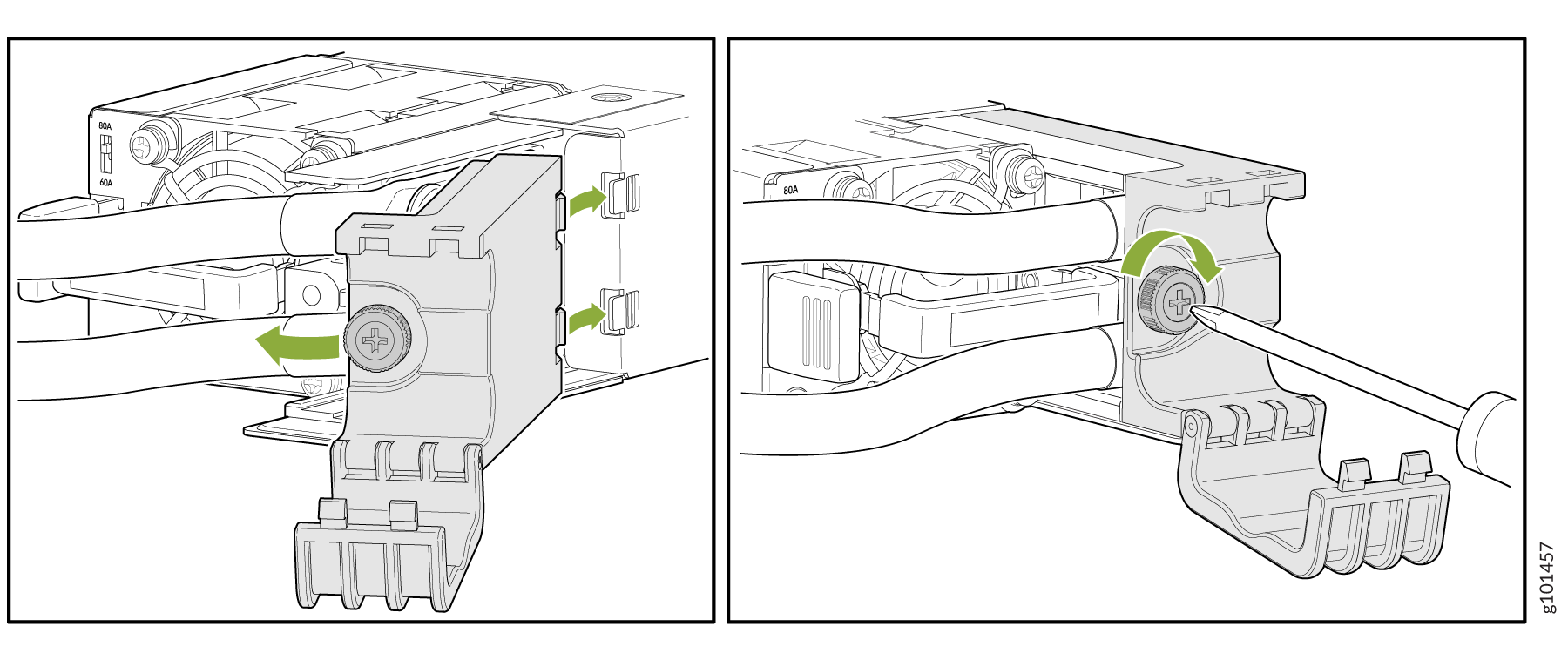
Use a Phillips screwdriver to loosen the screw holding the cable manager
latch to the power supply terminal block cover. See Figure 2.
Figure 2: Removing the DC Power Supply Unit Cable Manger Latch
-
Install heat-shrink tubing insulation around the power cables.
To install heat-shrink tubing:
-
Slide the tubing over the portion of the cable where it is attached to the lug barrel. Ensure that tubing covers the end of the wire and the barrel of the lug attached to it.
-
Shrink the tubing with a heat gun. Ensure that you heat all sides of the tubing evenly so that it shrinks around the cable tightly.
Figure 3 shows the steps to install heat-shrink tubing.
Note:Do not overheat the tubing.
Figure 3: How to Install Heat-Shrink Tubing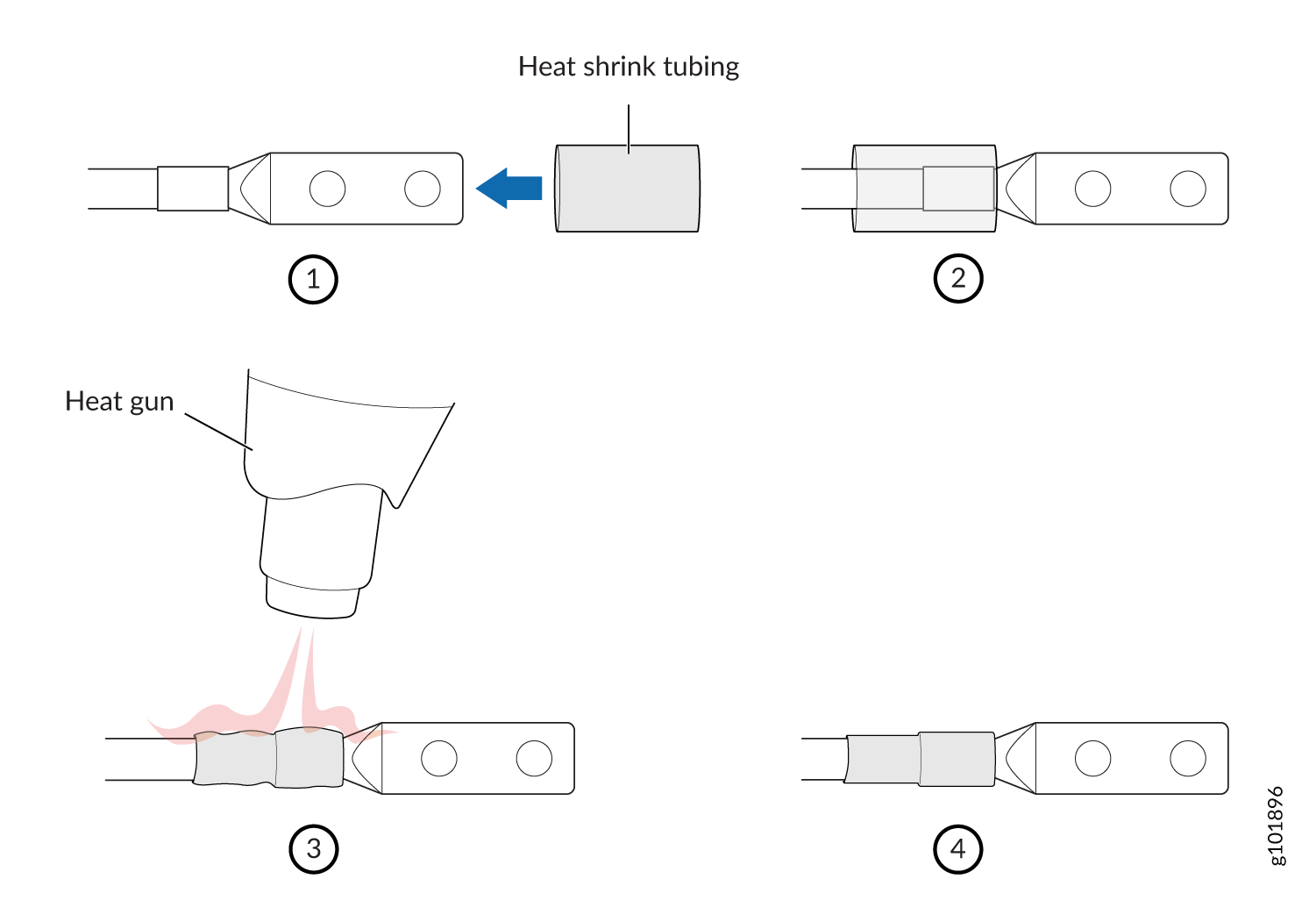
-
-
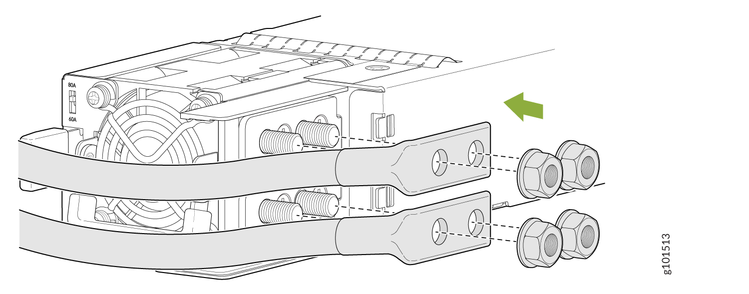
If you are using straight DC power cables, place the ends of the power
cable connectors over the four terminal studs.
Figure 4: Connecting the DC Power Cables to Terminal Studs
-
Reattach the cable manager latch that you removed in Step 6, and tighten
the thumb screw. See Figure 5.
Figure 5: Reattaching the Cable Manager Latch
-
Close the cable manager latch to hold the power cables in place.
Note:
Ensure that the power cables do not block access to device components or trail across the floor where people could trip over them.