Connect an ACX7509 Router to External Devices
You configure and manage the ACX7509 router using a dedicated management channel. The Routing and Control Board (RCB) in the ACX7509 router has a console port that you connect to using an Ethernet cable with an RJ-45 connector.
Connect an ACX7509 Router to a Management Console
Use the console port to connect the router to the console server or management console. The console port accepts a cable that has an RJ-45 connector.
Ensure that you have an RJ-45 to DB-9 rollover cable available.
We no longer include the RJ-45 console cable with the DB-9 adapter as part of the device package. If the console cable and adapter are not included in your device package, or if you need a different type of adapter, you can order the following separately:
-
RJ-45 to DB-9 adapter (JNP-CBL-RJ45-DB9)
-
RJ-45 to DB-9 adapter (JNP-CBL-RJ45-DB9)
-
RJ-45 to USB-C adapter (JNP-CBL-RJ45-USBC)
If you want to use RJ-45 to USB-A or RJ-45 to USB-C adapter you must have X64 (64-Bit) Virtual COM port (VCP) driver installed on your PC. See, https://ftdichip.com/drivers/vcp-drivers/ to download the driver.
If your laptop or PC does not have a DB-9 plug connector pin and you want to connect your laptop or PC directly to the RCB, use a combination of the RJ-45 cable and RJ-45 to DB-9 adapter and a USB to DB-9 plug adapter (not provided).
To connect the ACX7509 router to a management console:


Connect an ACX7509 Router to a Network for Out-of-Band Management
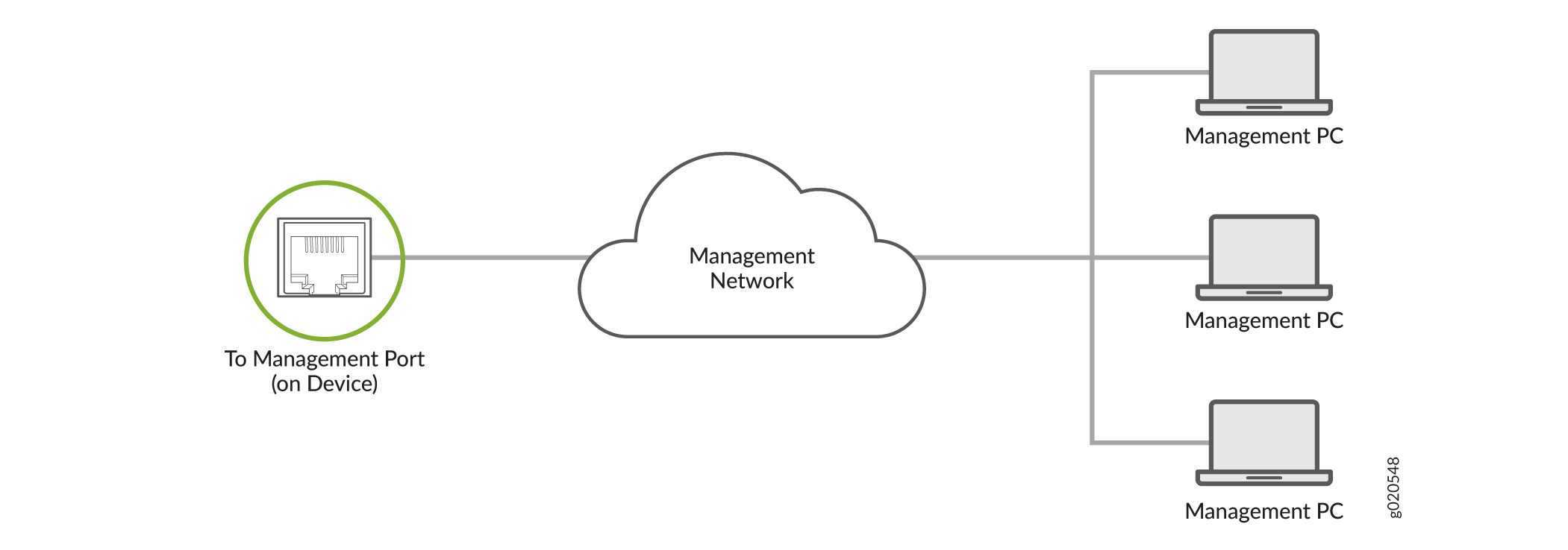
You can monitor and manage the ACX7509 router by using a dedicated management channel. The Routing and Control Board (RCB) has a management port to which you can connect an Ethernet cable with an RJ-45 connector. Use the management port to connect the ACX7509 router to a network for out-of-band management.
Ensure that you have an appropriate cable available. See ACX7509 Transceiver Support and Network Cable Planning.
To connect the router to a network for out-of-band management:
-
Connect the other end of the Ethernet cable to the management device.
Figure 3: Connect an ACX7509 Router to a Network for Out-of-Band Management
Connect an ACX7509 Router to External Clocking and Timing Devices
The RCB has four DIN connector ports that support 1-PPS and 10-MHz Input and Output connectors.
Ensure that you use a cable of 3 m or less in length for the 10-MHz and 1-PPS connectors.
To connect the DIN-to-BNC coaxial cable to the external clocking input port:
-
Connect one end of the DIN-to-BNC coaxial cable to either the 1-PPS connector or the 10-MHz connector on the router.
-
Connect the other end of the DIN-to-BNC coaxial cable to the 1-PPS or 10-MHz measurement equipment.
Ensure that the 10-MHz or 1-PPS source network equipment contains low-voltage complementary metal oxide semiconductor (CMOS) or is compatible with low-voltage (3.3 V) transistor-transistor logic (TTL).