ACX7509 Chassis
Learn about the ACX7509 router chassis, the field replaceable units (FRUs) and their physical specifications.
ACX7509 Router Chassis
The router chassis is a rigid sheet metal structure that houses all the other components (see Figure 1, Figure 2, and Figure 3). The chassis fits in standard 800-mm (or larger) enclosed cabinets, 19-in. equipment racks, or telco open-frame racks. You can install up to five routers in one standard (48 U) rack if the rack can support their combined weight, which can be greater than 1100 lb (500 kg). See ACX7509 Physical Specifications for physical specifications of the ACX7509 Router.
Before removing or installing components of a router, attach an ESD strap to an ESD point and place the other end of the strap around your bare wrist. Failure to use an ESD strap can result in damage to the router.
You must connect the router to an earth ground before you power it on and during normal operation.
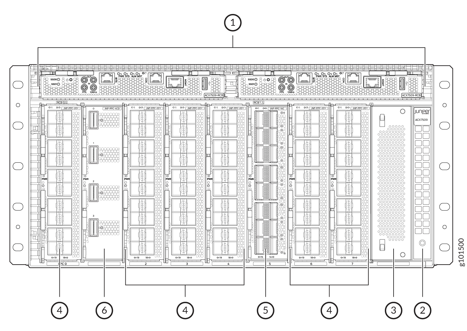
1 — Routing and Control Boards (RCBs) | 4 — JNP-FPC-20Y |
2 — ESD point | 5 — JNP-FPC-16C |
3 — Blank panel (JNP5K-FPC-BLNK) | 6 — JNP-FPC-4CD |
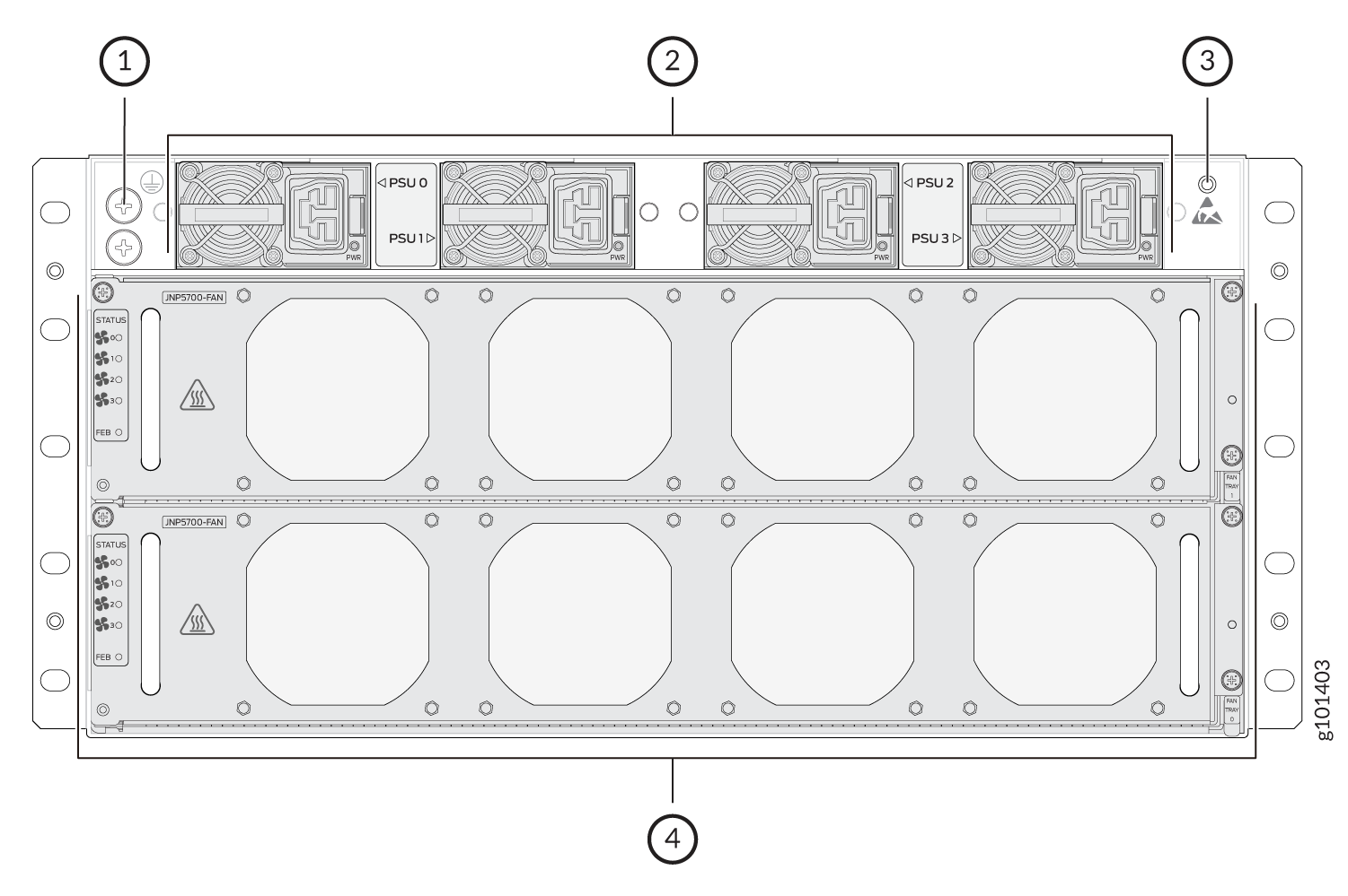
1 — Grounding earth terminal | 3 — ESD point |
2 — AC/HVDC Power Supply Modules | 4 — Fan trays |
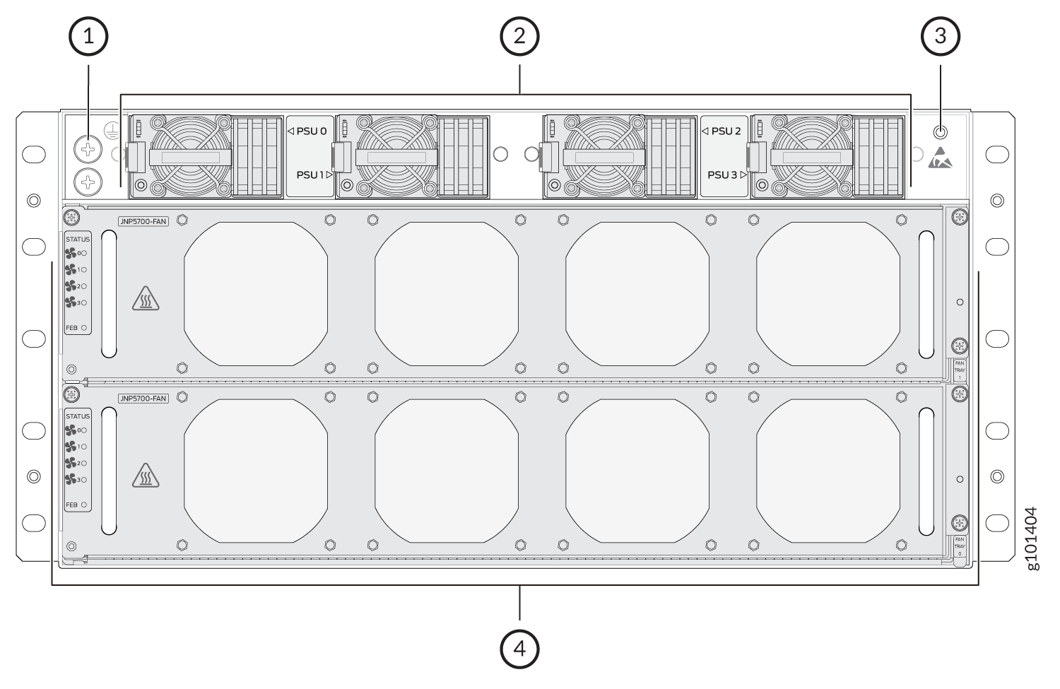
1 — Grounding earth terminal | 3 — ESD point |
2 — DC Power Supply Modules | 4 — Fan trays |
ACX7509 Physical Specifications
See Table 1, which summarizes the physical specifications of the router chassis and its components.
The ACX7509 is a 5U modular chassis and with the cable management system it is 6U.
|
Description |
Weight |
Height |
Width |
Depth |
|---|---|---|---|---|
|
Chassis |
Chassis (Sheet metal and Midplane) - 50.26 lb (22.8 kg) |
8.75 in. (22.2 cm) |
19 in. (48.2 cm) |
23.62 in. (60 cm) |
|
Fully loaded chassis (with the cable management system) - 175 lb (79.5 kg) |
10.51 in. (26.7 cm), with the cable management system |
19 in. (48.2 cm) |
31.49 in. (80 cm), with the cable management system |
|
|
ACX7509-RCB - Routing and Control Board (RCB) |
2.64 lbs (1.2 kg) |
1.22 in. (3.1 cm) |
8.42 in. (21.4 cm) |
9.25 in. (23.5 cm) |
|
ACX7509-FEB - Forwarding Engine Boards (FEBs) |
14.5 lbs (6.6 kg) |
3.3 in. (8.4 cm) |
17.20 in. (43.7 cm) |
11.06 in. (28.1 cm) |
|
JNP-FPC-16C |
4.4 lbs (2 kg) |
1.77 in. (4.5 cm) |
7.08 in. (18 cm) |
10.15 in. (25.8 cm) |
|
JNP-FPC-20Y |
4.4 lbs (2 kg) |
1.77 in. (4.5 cm) |
7.08 in. (18 cm) |
10.15 in. (25.8 cm) |
|
JNP-FPC-4CD |
4.4 lbs (2 kg) |
1.77 in. (4.5 cm) |
7.08 in. (18 cm) |
10.15 in. (25.8 cm) |
|
AC power supply |
3.3 lbs (1.5 kg) |
1.73 in. (4.4 cm) |
2.91 in. (7.4 cm) |
12.40 in. (31.5 cm) |
|
DC power supply |
3.3 lbs (1.5 kg) |
1.73 in. (4.4 cm) |
2.91 in. (7.4 cm) |
13.11 in. (33.3 cm) |
|
Fan tray |
7 lbs (3.2 kg) |
3.34 in. (8.5 cm) |
5.35 in. (13.6 cm) |
17.32 in. (44 cm) |
ACX7509 Router Midplane Description
The midplane is located on the rear of the chassis and forms the rear of the card cage. You install the Routing and Control Boards (RCBs) and the Flexible PIC Concentrators (FPCs) in the midplane from the front of the chassis. You install the Forwarding Engine Boards (FEBs), power supply units, and the fan trays in the midplane from the rear of the chassis.
The midplane performs the following major functions:
-
Distributes power—The power supplies connect to the midplane, which distributes power to all the router components.
-
Provides a signal path—The midplane provides the signal path to the FPCs, RCBs, FEBs, and other system components for system monitoring and control.
ACX7509 Cable Management System
The ACX7509 routers supports the cable management system. It can be used for both ACX7509-BASE and ACX7509-PREMIUM configurations.
For ACX7509 routers you can use the cable management system to organize, support, and provide strain relief for the cables connected to the Routing and Control Boards (RCBs) and Flexible PIC Concentrators (FPCs). The cable management system helps you maximize airflow through the chassis by using cable ties or strips to organize the cabling.
You need to necessarily attach the Cable manager system when you install seven or more line cards of the same model.
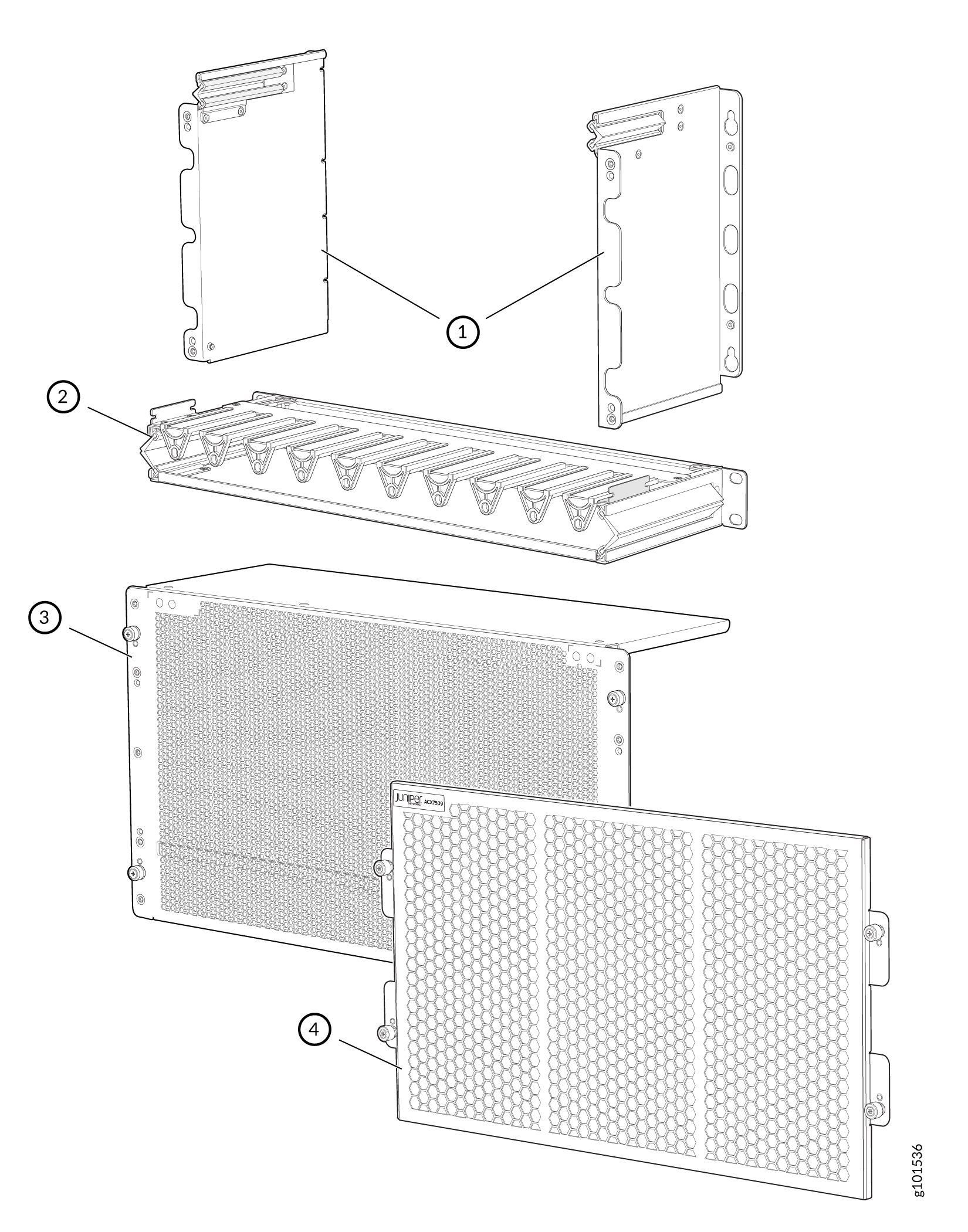
1 — Left and right side covers | 3 — Cable manager door |
2 — Fiber management tray | 4 — Air filter door |