ACX7509 Routing and Control Board
The ACX7509-RCB Routing and Control Board (RCB) provides routing protocol processes and software processes that control the router’s interface, the chassis components, system management functions, and user access to the router.
The RCB is an integrated board and a single field-replaceable unit (FRU) that provides Routing Engine and Control Board (CB) functionality. The Routing Engine performs all route-processing functions, whereas the CB performs chassis control and management plane functionality. The RCB provides control plane functions.
You can install one or two RCBs on the ACX7509 router. The base configuration ships with one RCB, and a redundant configuration ships with two RCBs. When two RCBs are installed, one functions as the primary RCB and the second functions as a backup RCB. If you remove the primary RCB and have configured graceful Routing Engine switchover (GRES), the backup RCB becomes the primary RCB.
The RCB integrates the control plane and Routing Engine functions into a single management unit. Each RCB provides all the functions needed to manage the chassis operation:
-
System control functions such as environmental monitoring
-
Routing Layer 2 and Layer 3 protocols
-
Communication to all components such as FPCs, FEBs, power, and cooling
-
Transparent clocking
-
Alarm and logging functions
Table 1 summarizes the physical specifications of the RCB.
| Description | Value |
|---|---|
|
Height |
1.22 in. (3.1 cm) |
|
Width |
8.42 in. (21.4 cm) |
|
Depth |
9.25 in. (23.5 cm) |
|
Weight |
2.64 lbs (1.2 kg) |
|
Power requirement |
|
Each RCB includes the following internal components:
-
CPU—High-performance 2.9-GHz Intel 6 Core X86 CPU
-
DRAM—64-GB DDR4 RAM
-
Solid-state drive (SSD)—Two 100-GB SATA SSDs
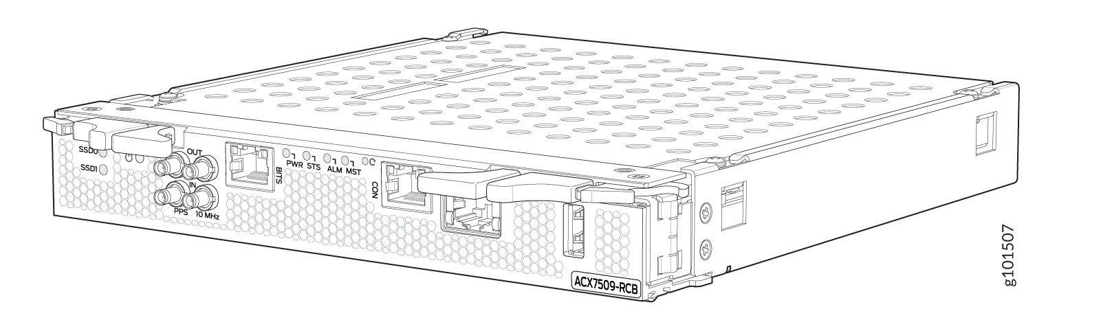
Routing and Control Board Front Panel
Figure 2 shows the front panel of the ACX7509 RCB.
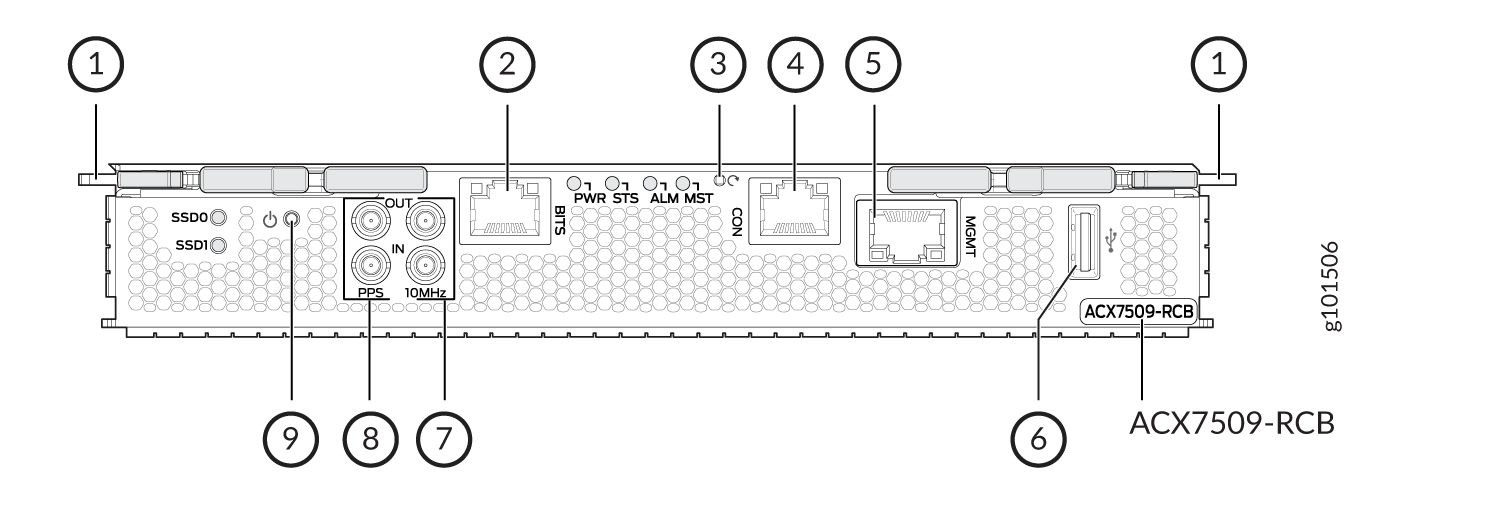
1 — Ejector handles | 6 — USB port |
2 — BITS clock port with LEDs | 7 — 10MHz IN/OUT ports |
3 — Reset button | 8 — PPS IN/OUT port |
4 — Console (CON) port | 9 — Online/Offline button |
5 — Management (MGMT) port |
The ports located on the RCB connect the RCB to one or more external devices on which system administrators can issue Junos OS Evolved CLI commands to manage the router. In addition, the RCB includes ports that you use to connect external clock interfaces for BITS and GPS functions.
The RCB interface ports with the indicated labels function as follows:
-
CON—Connects the RCB to a system console through a serial cable with an RJ-45 connector.
-
MGMT—Connects the RCB through an Ethernet connection to a management LAN (or any other device that plugs into an Ethernet connection) for out-of-band management. The port uses an autosensing RJ-45 connector to support 10-Mbps, 100-Mbps, or 1000-Mbps connections. Two small LEDs (an activity LED and a link LED) on the port indicate that the connection is in use.
The link LED is:
-
Green (steady) when the 1000-Mbps link is up.
-
Orange (steady) when the 10/100-Mbps link is up.
-
Off when the link is down.
The activity LED is:
-
Green (blinking) when traffic is passing through the port.
-
Off when traffic is not passing through the port.
Both activity and link LEDs are off when the link is down.
-
-
BITS—Building-integrated timing system (BITS) is the external clocking interface for connecting to external clocking devices.
-
10MHZ (one input and one output)—The 10-MHz timing connectors on the front panel of the router connect to external clock signal sources. The clocking ports provide the synchronized output clocks from any one of the reference clock inputs, based on the clock’s priority.
-
PPS (one input and one output)—1-pulse-per-second (PPS) connector on the front panel of the router connects to external clock signal sources. The clocking ports provide the synchronized output clocks from any one of the reference clock inputs, based on the clock’s priority.
-
USB—Provides a removable media interface through which you can install Junos OS Evolved manually. Junos OS Evolved supports USB version 2.0 and later.
The following buttons are located on the RCB:
-
RESET button—When pressed, reboots the RCB as follows:
-
Short press reboots the RCB and the reset-reason logs the button press event. The press event is logged in the RCB FPGA register.
-
When pressed for more than 10 seconds, the RCB reboots with an option for BIOS recovery.
-
-
Online/Offline button—When the RCB is offline and if the button is pressed (short press), the RCB starts booting. When the RCB is online and if the button is pressed for four seconds or more (long press), the RCB shuts down.
Routing and Control Board LEDs
The LEDs—labeled SSD0, SSD1, PWR, STS, ALM, and MST—are located on the faceplate of the RCB.
The RCB controls the ACX7509 router, and the LEDs on the RCB display the status and functioning of the ACX7509 chassis. See Table 2.
| LED | Color | State | Description |
|---|---|---|---|
|
SSD0 and SSD1 |
Green |
On steadily |
The drive is detected. |
|
Green |
Blinking |
The drive is active. |
|
|
PWR |
Green |
On steadily |
The RCB is receiving adequate power. |
|
Blinking |
The beacon feature is enabled. |
||
|
Dark |
Off |
The RCB is booting. |
|
|
STS |
Green |
On steadily |
The RCB is online and functioning correctly. |
|
Green |
Blinking |
The beacon feature is enabled. |
|
|
Yellow |
On steadily |
The RCB is booting. |
|
|
Yellow |
Blinking |
An error has been detected in the RCB. |
|
|
Dark |
Off |
The power supply is switched off. |
|
|
ALM |
Dark |
Off |
The router is halted, or there is no alarm. |
|
Red |
On steadily |
A major hardware fault has occurred, such as a temperature alarm or power failure, and the router has halted (except during a single rotor failure in a fan module). Switch off power to the router and unplug the power cords. Correct any voltage or site temperature issues, and allow the router to cool down. Power on the router, and monitor the power supply and fan LEDs to determine where the error is occurring. |
|
|
Blinking |
Indicates the presence of a major and a minor alarm. |
||
|
Yellow |
On steadily |
A minor alarm has occurred, such as a software error. Switch off power to the router and unplug the power cords. Power on the router, and monitor the status LEDs to ensure that Junos OS Evolved boots up properly. |
|
|
Red+Yellow |
Blinking |
Indicates the presence of a major and a minor alarm. |
|
|
MST |
Green |
On steadily |
This RCB is the primary RCB. |
|
Dark |
Off |
This RCB is the backup RCB. |
|
|
BITS |
Green |
On steadily |
The BITS external clocking interface is active. |
|
Yellow |
On steadily |
The BITS external clocking interface has failed. |