Cooling System and Airflow in ACX7509 Routers
The cooling system components work together to keep all router components within the acceptable temperature range.
When the router is operating normally, the fans function at lower than full speed. If a fan fails or the ambient temperature rises above a threshold, the speed of the remaining fans is automatically adjusted to keep the temperature within the acceptable range. If the maximum temperature specification is exceeded and the system cannot be adequately cooled, the Routing and Control Board (RCB) shuts down some or all of the hardware components.
The cooling system consists of the following components:
-
Fan trays
-
Airflow
-
Air filter unit
-
Power supply cooling system
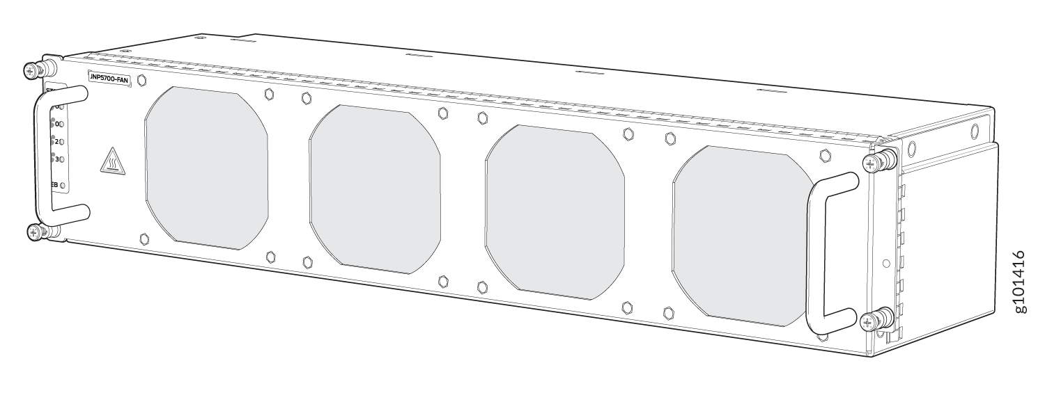
Fan Trays
The ACX7509 router has two hot-insertable and hot-removable field-replaceable fan trays that sit at the rear of the router (See Figure 1). The fan trays plug onto the midplane of the chassis through the fan tray extension card. Each fan tray contains these parts:
-
Four dual-rotor, counter-rotating fans
-
A fan controller card
-
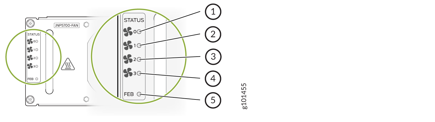
Five STATUS LEDs: Four LEDs with the fan symbol indicate the operating condition of the counter-rotating fans and the fifth FEB LED indicates the operating condition of the Forwarding Engine Board (FEB) installed in the FEB slot behind the fan tray. See Figure 2.
Fan Status LEDs
Each fan has one bicolor LED. See Figure 2
-
1 - 4 - Status of the four dual-rotor, counter-rotating fans
-
5 - Status of the FEB behind the fan tray
Table 1 describes the behavior of the fan and FEB LEDs.
| Label | Color | State | Description |
|---|---|---|---|
|
STATUS (Fan status) |
Green |
Blinking |
Fan hardware initialization is complete. Software initialization is pending |
|
On steadily |
Software initialization is complete, and the fan is functioning normally |
||
|
Yellow |
On steadily |
Equipment is faulty and malfunctioning |
|
|
Dark |
Off |
Fan tray input power failure |
|
|
FEB (FEB status) |
Green |
Blinking |
The FEB is booting |
|
On steadily |
The FEB is online and functioning normally |
||
|
Yellow |
On steadily |
The FEB has failed |
|
|
Dark |
Off |
The FEB is offline |
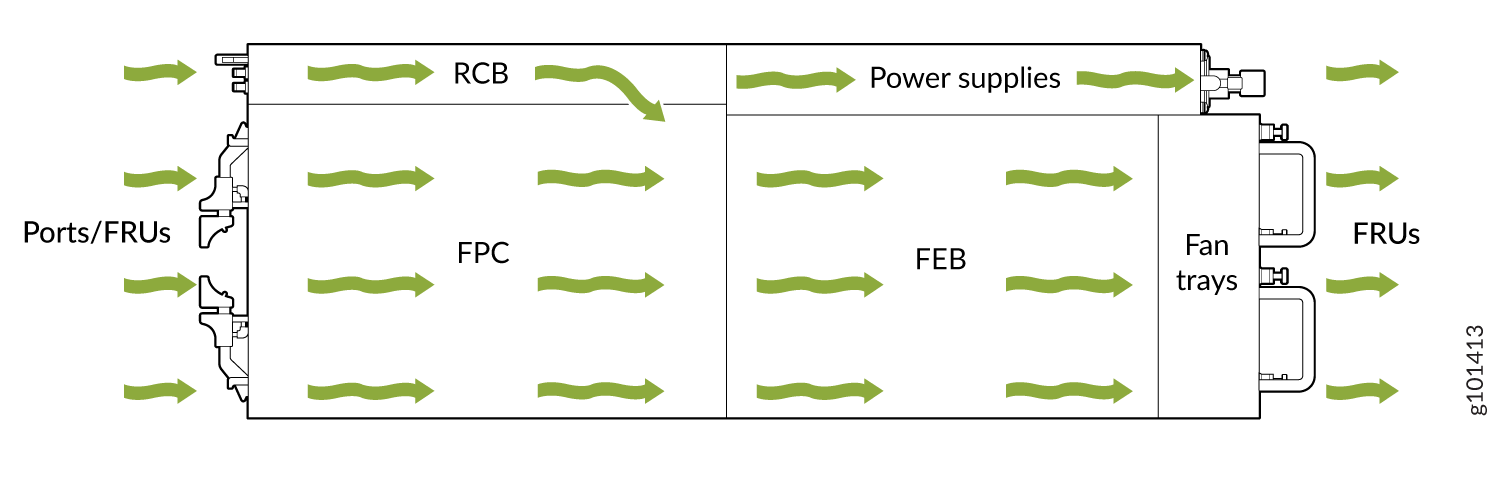
Airflow
The router has a front-to-back (AIR OUT) cooling system (see Figure 3). Air is pulled through the front of the chassis toward the fan trays, which exhaust the air out of the router.
Air Filter Unit
The air filter unit consists of three parts: the outer filter cover, the air filter, and the inner cage. The air filter sits right inside the outer filter cover and the inner cage. The air filter unit is installed into the cable management brackets and is secured to the brackets by captive screws.
You must replace the air filter every 6 months.
Power Supply Cooling System
The power supplies are self-cooling and are located in the rear of the router.
There are multiple airflow ducts on the front of the chassis that provide fresh air to the PSMs to maintain the thermal requirements.