Connect ACX7348 to External Devices
You configure and manage the ACX7348 router using a dedicated management channel. The Routing Engine in the ACX7348 router has a console port that you connect to using an Ethernet cable with an RJ-45 connector.
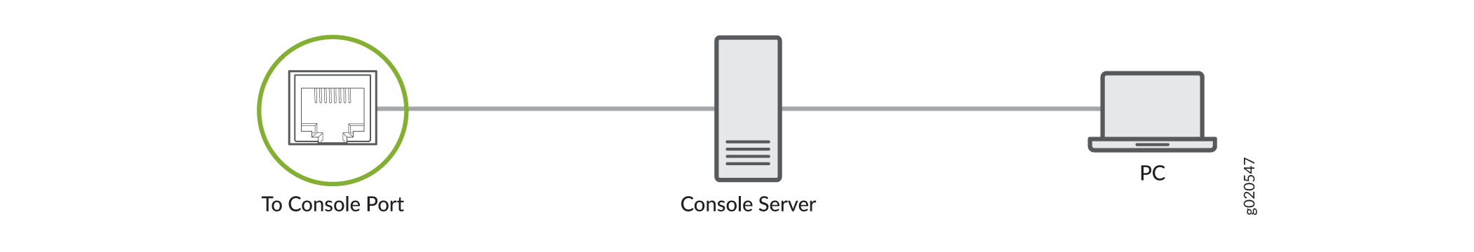
Connect an ACX7348 Router to a Management Console
Each ACX7348 router has a console port with an RJ-45 connector. Use the console port to connect the device to a management console or to a console server.
To connect the ACX7348 router to a management console:
- Connect one end of the Ethernet cable to the console port (labeled CON).
- Connect the other end of the Ethernet cable into the console server (see Figure 1) or management console (see Figure 2).

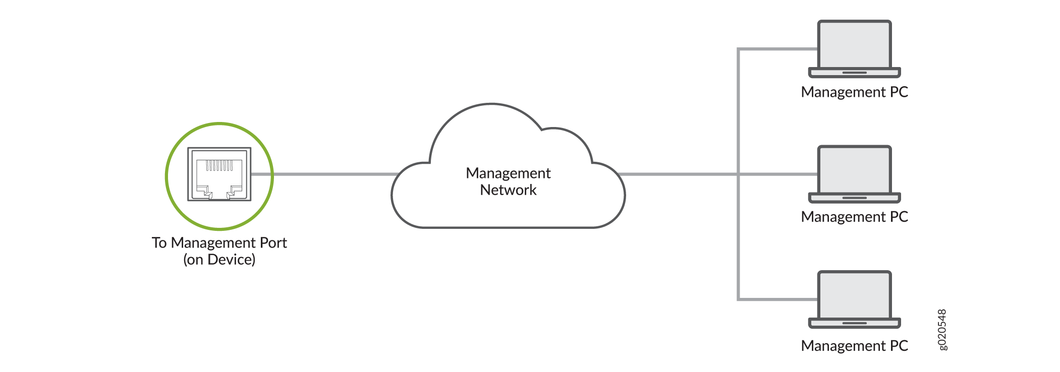
Connect an ACX7348 Router to a Network for Out-of-Band Management
You can monitor and manage the ACX7348 router by using a dedicated management channel. Use the management ports to connect the ACX7348 router to a network for out-of-band management.
You cannot use the management ports to perform the initial configuration of the ACX7348 router. You must configure the management ports before you can successfully connect to the ACX7348 router using these ports. See Perform Initial Software Configuration for ACX7348 Routers.
To connect an ACX7348 router to a network for out-of-band management:
- Connect one end of the cable to the management port labeled MGMT on the ACX7348 router.
- Connect the other end of the cable to the management PC (see Figure 3).
Connect to 1-PPS and 10-MHz Timing Devices
Each ACX7348 router has two DIN 1.0/2.3 female connector ports that support 1 pulse per second (1‑PPS) and 10-megahertz (10-MHz) inputs and outputs for interface to external timing devices.
Ensure that you use a cable of 3 m or less in length for the 10-MHz and 1-PPS connectors.
To connect the DIN-to-BNC coaxial cable to the external clocking input port:
Connect an ACX7348 Router to a GNSS Antenna
Global Navigation Satellite System (GNSS) capability is essential for the Grand Master (GM) clock functionality. The ACX7348 router supports an internal GNSS receiver. A GNSS receiver receives signals from a navigation satellite constellation. The GNSS receiver gains precise phase and time information by processing these signals and delivers the information across the network.
You must install a GNSS antenna to ensure optimal signal reception. Juniper supports the Furuno AU-300 antenna. For information about installing the AU-300 antenna, see the AU-300 Installation Procedure.
The supported voltage values for the GNSS antenna are 3.3 V and 5 V. The default supported voltage for the antenna is 5 V.
To order the Furuno AU-300 antenna and related accessories, see Accessories for Juniper Customers.
Before you connect an ACX7348 router to the external GNSS antenna:
-
Understand the antenna cable specifications. See Antenna Cable Specifications.
-
Follow the instructions in Cabling Guidelines.
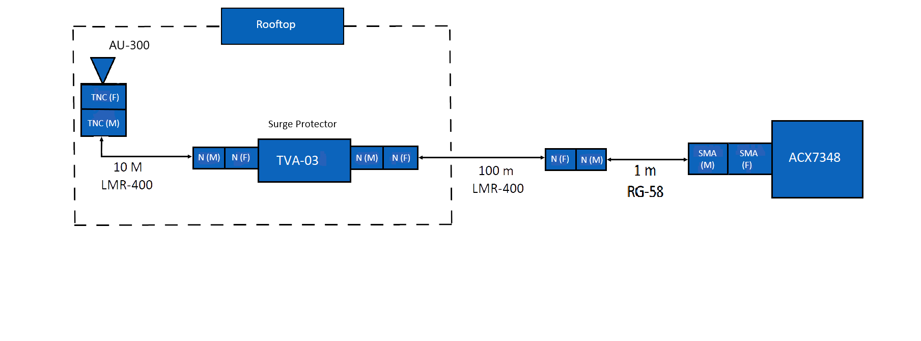
To connect an ACX7348 router to a GNSS antenna, refer the topology depicted in Figure 4.
Gain and Noise Figure Calculation
To calculate the total gain and noise figure (NF), see GNSS Antenna Installation Appendix on the Furuno data download page.
Antenna Cable Specifications
The following topology (Figure 4) depicts the antenna cable connections with connector types. Use this topology as an example to install the antenna cables.
 Juniper
has tested this topology with the following cables:
Juniper
has tested this topology with the following cables:
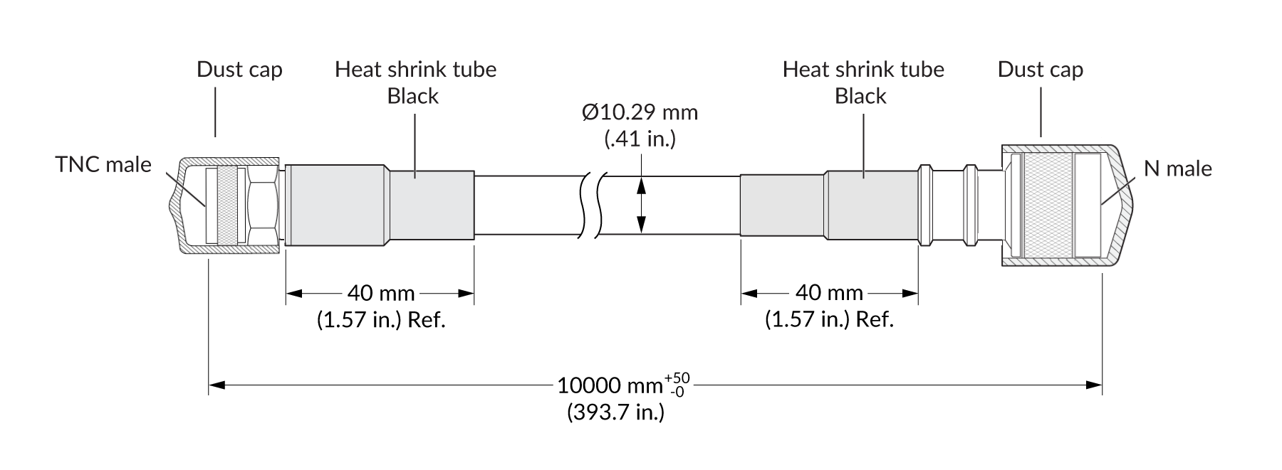
-
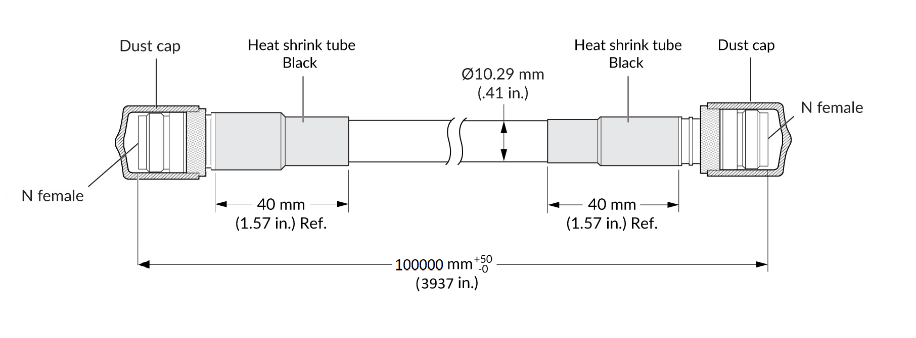
LMR400 (10-m segment) from TE Connectivity. For more information, see Figure 5.
-
LMR400 (100-m segment) from TE Connectivity. For more information, see Figure 6.
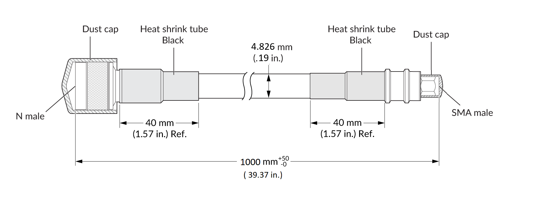
-
RG-58 (1-m segment) from TE Connectivity. For more information, see Figure 7.
You must ensure that you install a surge protector to protect the GNSS receiver from lightning surges. This topology uses TVA-03C surge protectors. For more information about the surge protectors, see Coaxial lightning arrestor TVA-03.
|
LMR400 |
|
|---|---|
|
Impedance |
50 Ω |
|
Frequency |
DC-3GHz |
|
Voltage rating |
335 Vrms |
|
Dielectric withstanding voltage |
> 1000 V |
|
Insulation resistance |
> 5000 MΩ |
|
RG58 |
|
|---|---|
|
Impedance |
50 ± 2 Ω |
|
Capacitance |
100 pF/m |
|
Velocity Ratio |
66 % |
|
Resistance |
Inner Conductor- 36, 5 Ω/Km Braid- 14 Ω/Km |
| Tension |
Sheath and Spark testing- 4,0 kV |
Cabling Guidelines
Follow these guidelines when you install cables:
-
Examine the cable end points and connectors for any bends or damage.
-
Check the electrical continuity of the cable for both inner and outer conductors.
-
Check for any electrical short in cables.
-
Inspect the cable outer sheath for any damage.