Install the ACX7332 in a Rack
Use the information in this topic to install the ACX7332 router in a rack.
You can install an ACX7332 router into a two-post rack, four-post rack, or a cabinet.
Install an ACX7332 in a Two-Post Rack
Be sure that you have the following parts and tools available to install the router:
-
Four M5 screws to secure the mounting brackets to the rack—provided
-
A Phillips (+) screwdriver, number 2—not provided
-
An ESD grounding strap—provided
We ship the ACX7332 routers with preinstalled two-post mounting brackets.
To mount an ACX7332 router on two posts of a rack:
-
If you are using a mechanical lift:
-
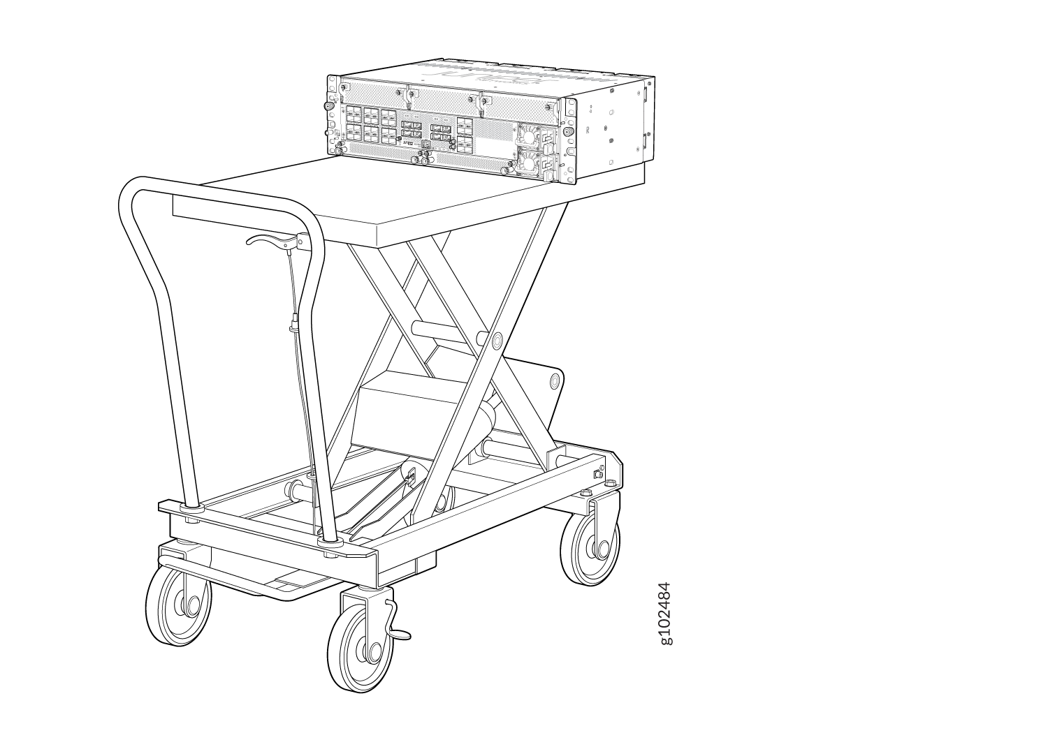
Load the router onto the lift, making sure it rests securely on the
lift platform.
Figure 1: Load the ACX7332 onto a Mechanical Lift
-
Load the router onto the lift, making sure it rests securely on the
lift platform.
-
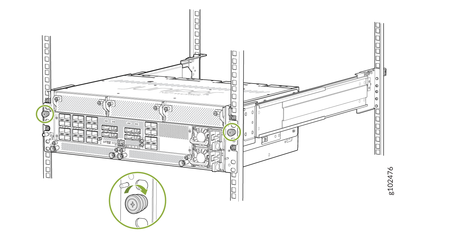
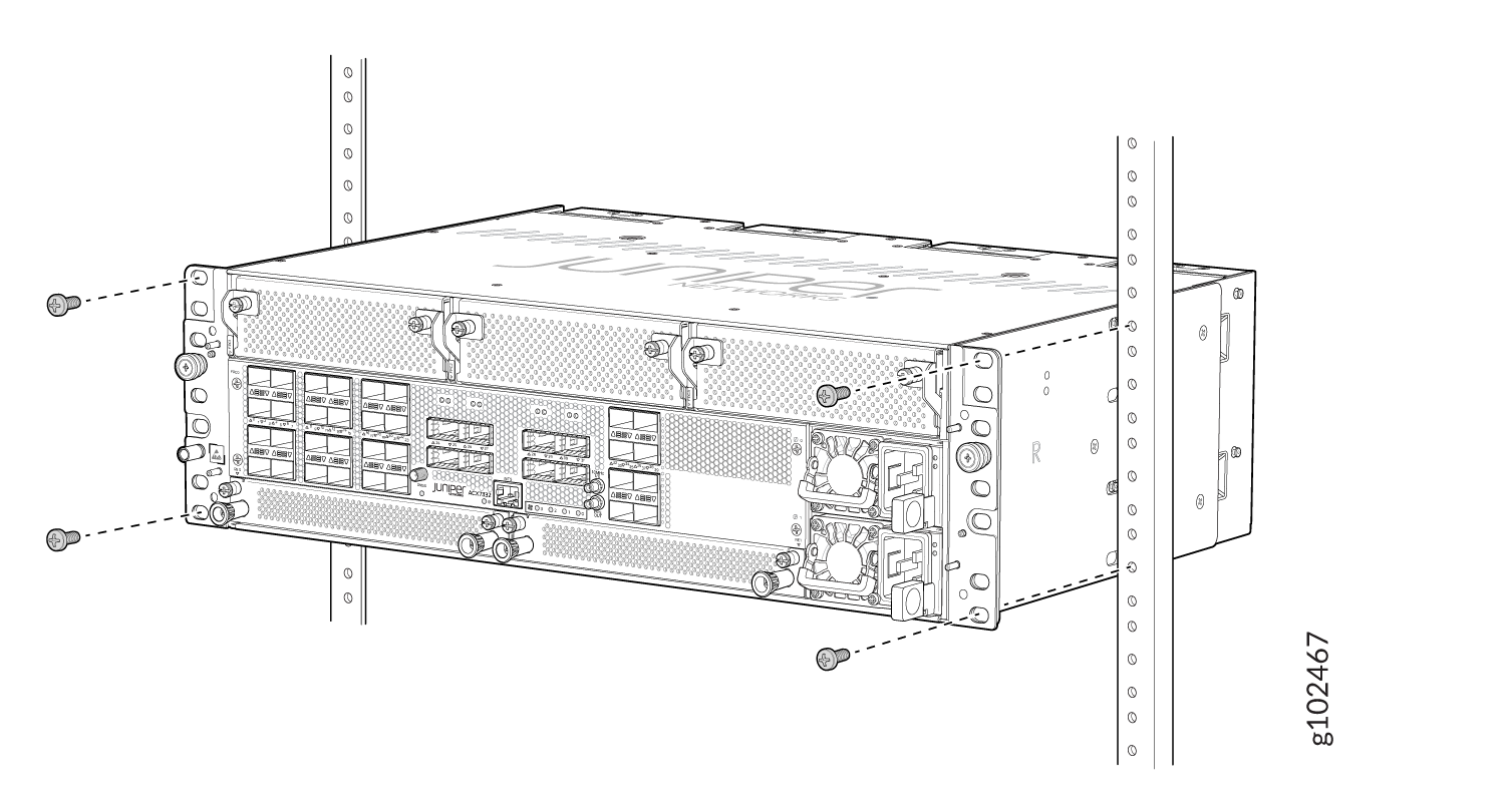
Secure the mounting brackets to the rack by using four M5 screws
(provided). Tighten the screws.
Figure 2: Secure the Router Flush with the Posts of the Rack
-
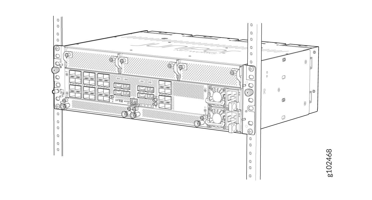
Ensure that the chassis is level by verifying that all screws on one side
of the rack align with the screws on the other side.
Figure 3: ACX7332 Router Installed in a Two-Post Rack
Install an ACX7332 in a Four-Post Rack
Be sure that you have the following parts and tools available to install the router:
-
An ESD grounding strap—provided
-
A Phillips (+) screwdriver—not provided
-
Telescopic rail kit that consists of the following components:
Table 1: Components in Telescopic Rail Kit Item
Description
Telescopic rail assembly
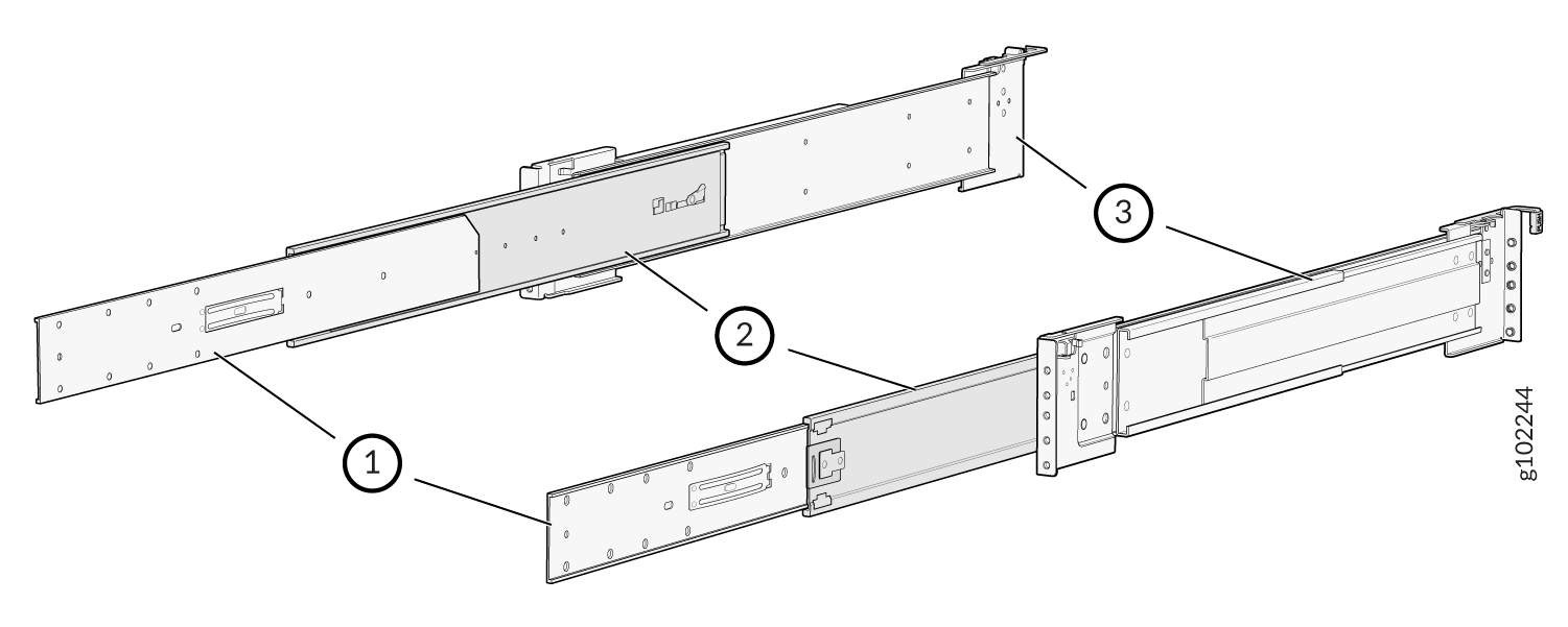
-
Removable telescopic rail bracket
-
Middle telescopic rail
-
Fixed telescopic rail
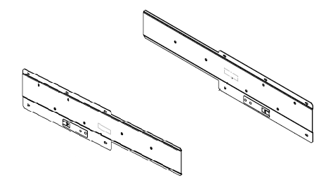
Left and right chassis brackets
Pack of screws that contain the following:
-
8 M4 flat head screws

-
6 M4 thin head screws

-
8 round hole pins

-
8 screw hole pins
 Note: Telescopic rail is supported on four post racks with depth in the range of 450 to 600 mm.
 -
To install the router in a four-post rack:
-
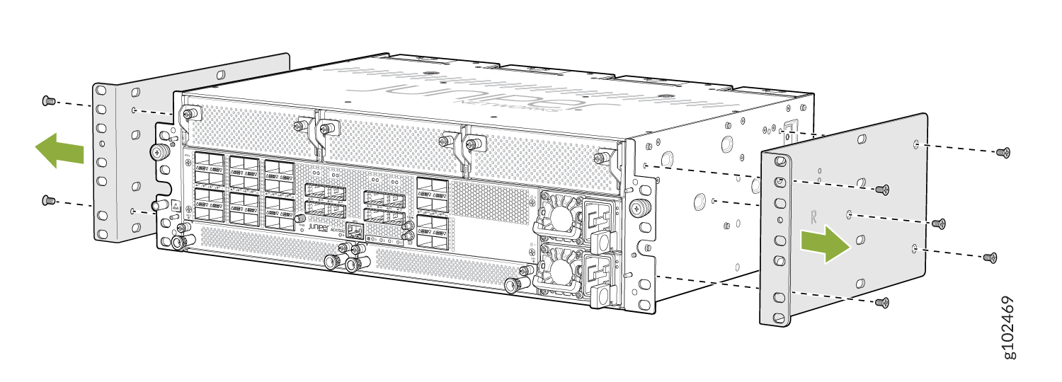
Using a Phillips screwdriver, remove the screws on each side of the
preinstalled two-post mounting brackets to remove the brackets.
Figure 4: Remove the Two-Post Mounting Brackets
-
Assemble the bracket assembly.
-
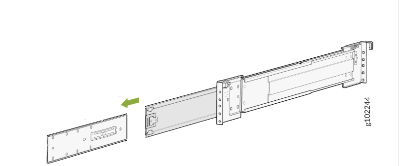
Pull out and detach the removable telescopic rail bracket from the
telescopic rail assembly. For information about the parts in a
telescopic rail assembly, see Table 1.
Figure 5: Detach the Telescopic Rail Bracket
-
Use the screws provided with the telescopic rail brackets to attach
the telescopic rail brackets over the chassis brackets.
Figure 6: Assemble the Bracket Assembly
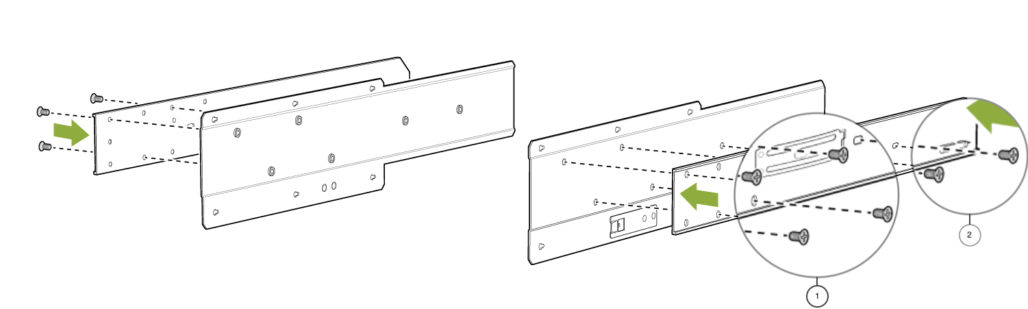
1. M4 flat head screws
2. M4 thin head screws
For information about the list of screws in the telescopic rail kit, see Table 1. -
Pull out and detach the removable telescopic rail bracket from the
telescopic rail assembly. For information about the parts in a
telescopic rail assembly, see Table 1.
-
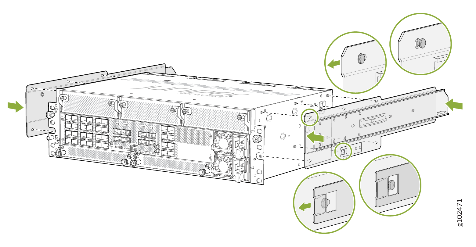
Attach the bracket assembly to the chassis.
-
Push the bracket assembly toward the front of the chassis to lock
the bracket assembly in place.
Figure 7: Attach the Bracket Assembly to the Chassis
-
Push the bracket assembly toward the front of the chassis to lock
the bracket assembly in place.
-
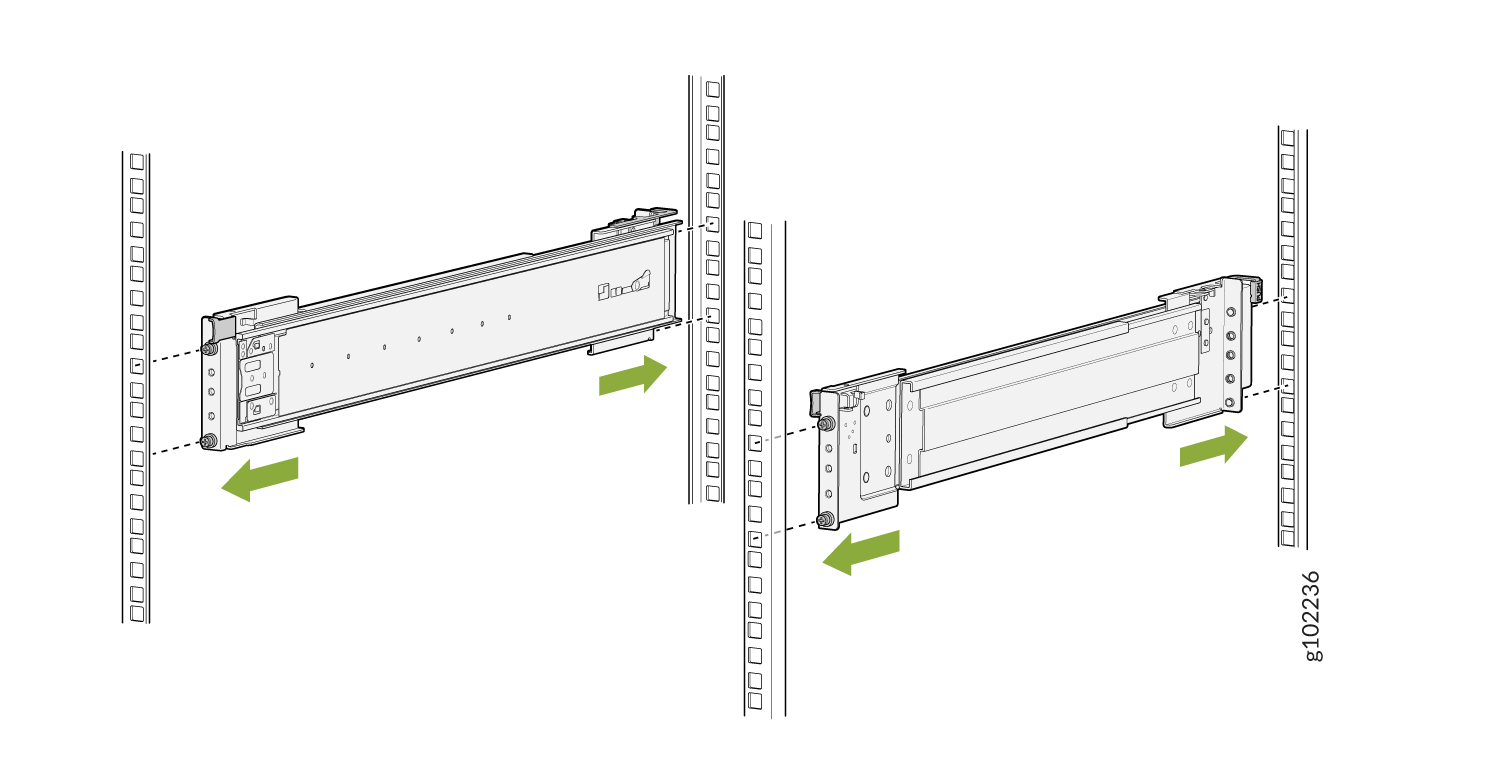
Attach the telescopic rails to the rack posts.
-
Attach the front end of the rails to the front rack posts.
Figure 8: Attach the Telescopic Rails to the Rack Rails
-
Attach the front end of the rails to the front rack posts.
-
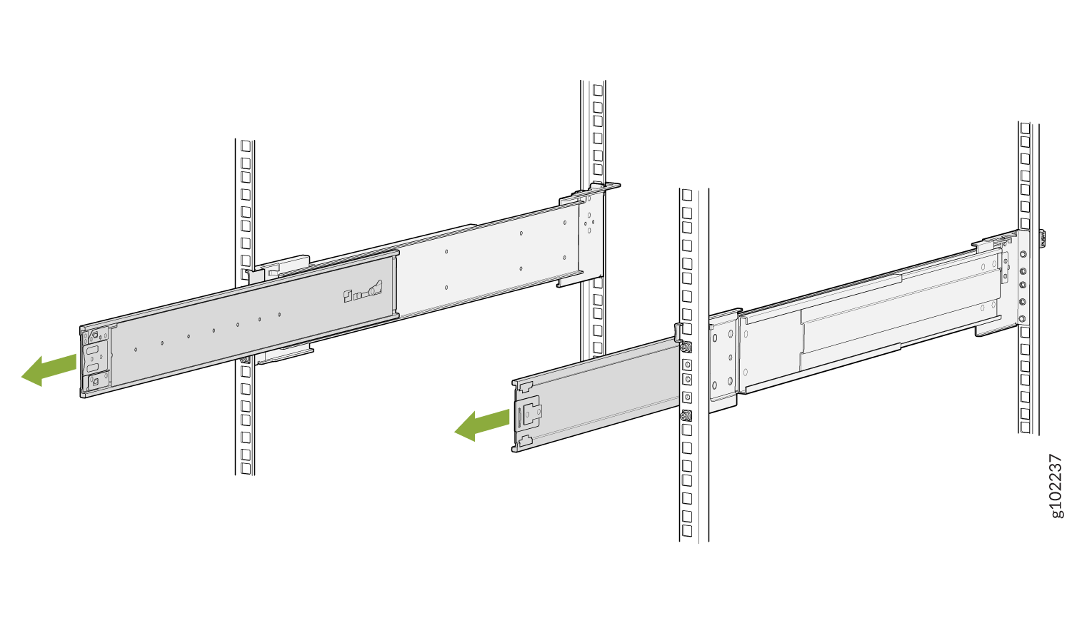
Extend the middle telescopic rails until you can't pull the rails out any
further.
Figure 9: Extend the Middle Telescopic Rails
-
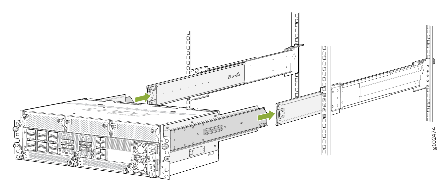
Grasp both sides of the router, lift it, and position the router so that
the removable telescopic rail attached to the chassis slides into the
channel of the middle telescopic rails.
Figure 10: Slide the Router into the Rack
-
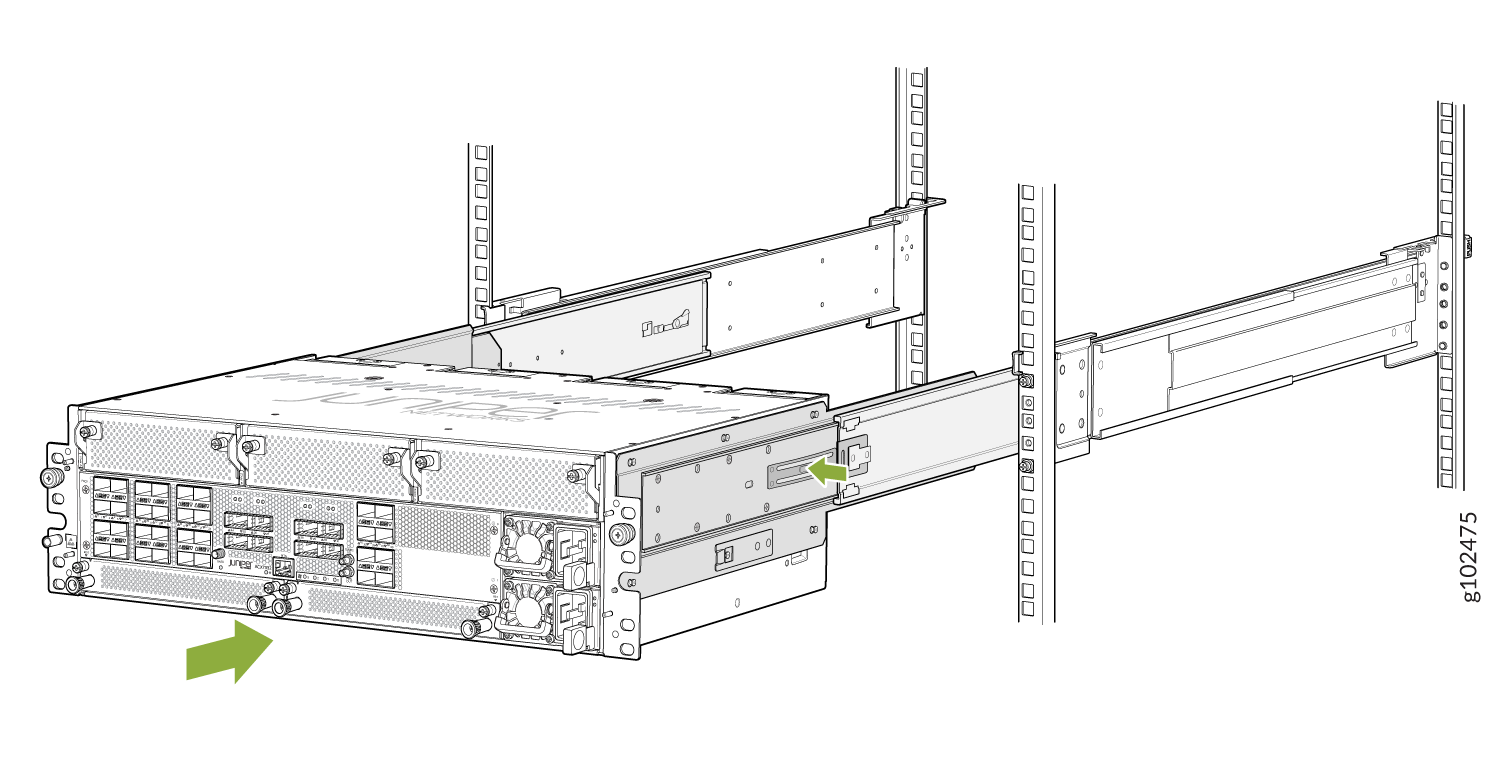
Press the latch on the side of the telescopic rail bracket to push the
chassis further until the front-mounting ears contact the front rack
rails.
Figure 11: Slide the Router into the Rack
-
Tighten the thumb screws on the mounting ears to secure the device.
Figure 12: ACX7332 Router Installed in a Four-Post Rack