ACX7332 Power Supply Module Maintenance
Maintaining an ACX7332 router includes replacing power supplies. Replacing includes removing a failed power supply and installing a functional power supply.
The power supply modules (PSMs) in an ACX7332 router are hot-removable and hot-insertable field-replaceable units (FRUs). You can remove and replace the PSMs without powering off the router or disrupting routing functions.
Remove an ACX7332 AC Power Supply Module
Before you remove a PSM from a router, ensure that you have taken the necessary precautions to prevent electrostatic discharge (ESD) damage (see Prevention of Electrostatic Discharge Damage).
Ensure that you have the following parts and tools available to remove a PSM from a router:
-
ESD grounding strap
-
Antistatic bag or an antistatic mat
To remove an AC PSM from an ACX7332 router:
-
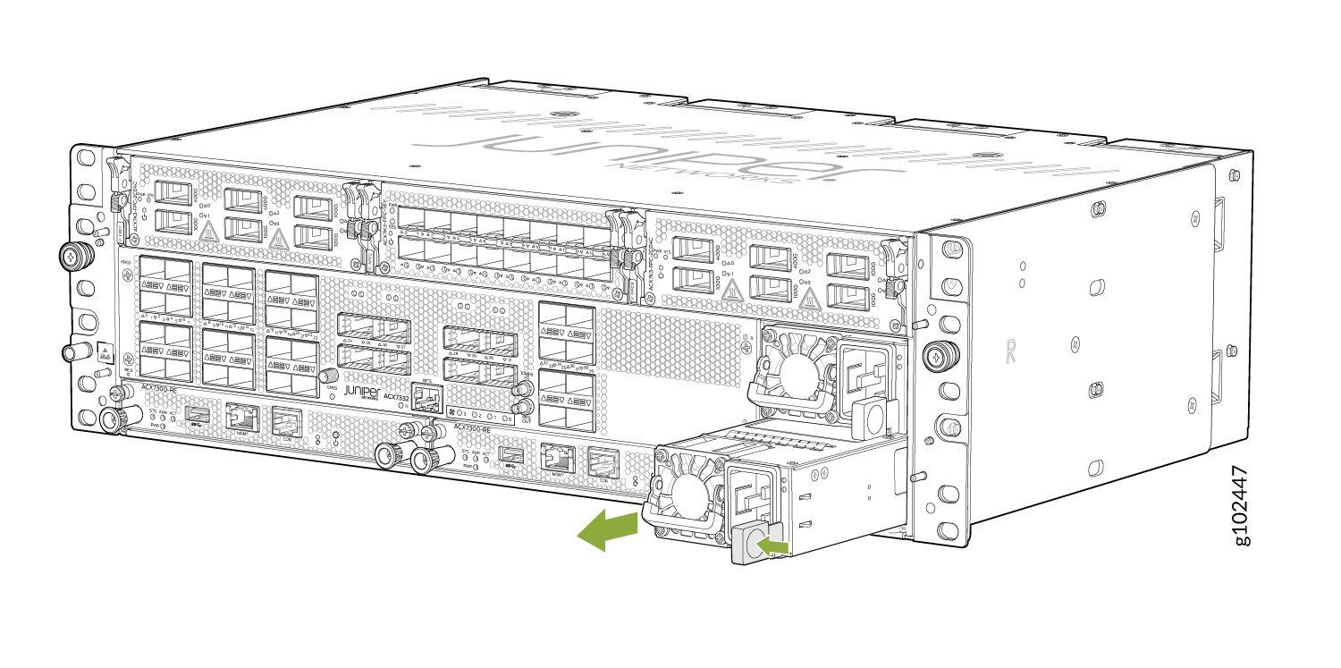
Slide the ejector lever toward the handle until you can no longer slide it
(see Figure 1)
Figure 1: Remove an AC PSM from the ACX7332 Router
Install an ACX7332 AC Power Supply Module
Before you install a PSM in a router, ensure that you have taken the necessary precautions to prevent electrostatic discharge (ESD) damage (see Prevention of Electrostatic Discharge Damage).
To install an AC PSM in an ACX7332 router:
-
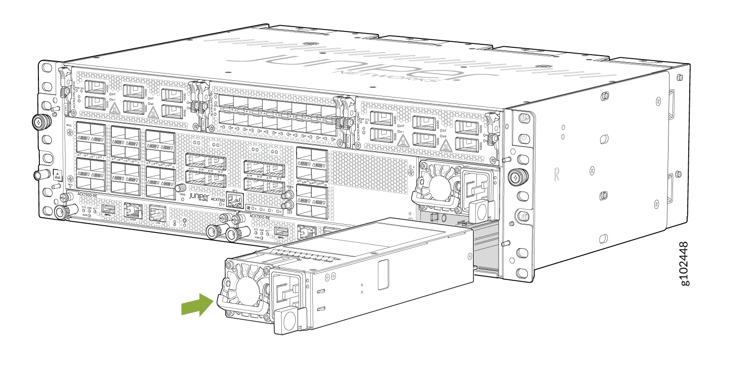
Using both hands, place the PSM in the power supply slot on the front panel
of the router and slide it in until it is fully seated and the ejector lever
slides into place (see Figure 2).
Figure 2: Install an AC PSM in an ACX7332 Router
-
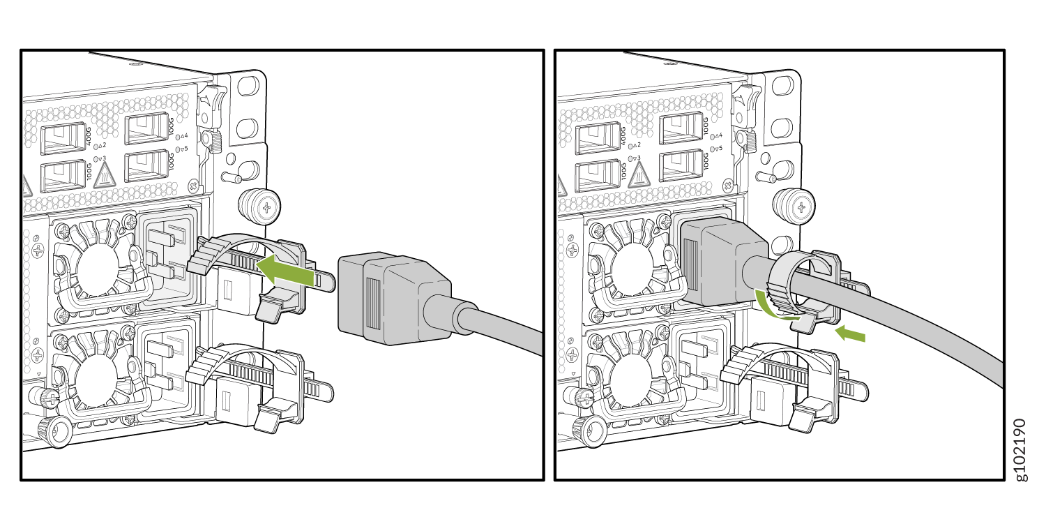
Attach the power cord to the PSM (see Figure 3).
Figure 3: Install an AC Power Cord on an ACX7332 Router
Remove an ACX7332 DC Power Supply Module
Before you remove a power supply module (PSM), be aware of the following:
The minimum required number of PSMs must always be present in the router.
Before performing DC power procedures, ensure that power is removed from the DC circuit. To ensure that all power is off, locate the two-pole circuit breaker on the panel board that services the DC circuit, switch the circuit breaker to the off position, and tape the switch handle of the circuit breaker in the off position.
To remove a DC PSM:
-
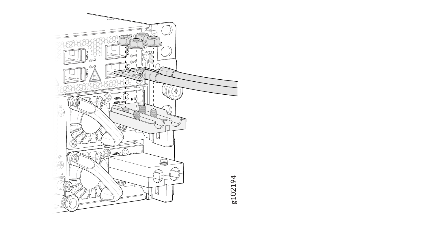
Using a Phillips screwdriver, remove the nuts from the DC power terminals
Figure 4: Removing the Nuts from the Terminals
Install an ACX7332 DC Power Supply Module
Before performing DC power procedures, ensure that power is removed from the DC circuit. To ensure that all power is off, locate the circuit breaker on the panel board that services the DC circuit, switch the circuit breaker to the off position, and tape the switch handle of the circuit breaker in the off position.
To install a DC PSM:
-
Connect to power.
-
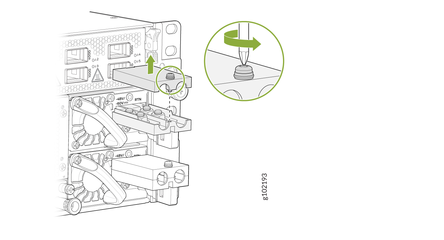
Remove the terminal block cover protecting the terminals on the
faceplate.
Figure 5: Removing the Terminal Block Cover
-
Remove the nuts from the terminals.
Figure 6: Removing the Nuts from the Terminals
-
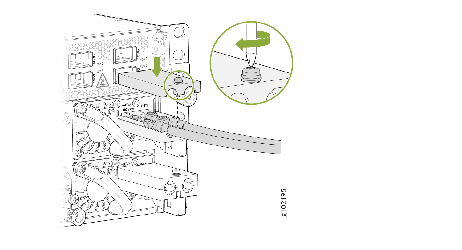
Replace the terminal block cover over the terminals on the
faceplate.
Figure 7: Connecting the DC Cable
-
Remove the terminal block cover protecting the terminals on the
faceplate.