ON THIS PAGE
ACX7332 Routing Engine
Learn about the ACX7300 Routing Engine and its specifications.
The ACX7332 Routing Engine provides control plane and chassis management functions. The Routing Engine provides high-performance compute horsepower and memory and storage infrastructure that enables the operating system to run. You can install one or two Routing Engines on the router. A redundant system hosts two Routing Engines, one being the primary and the other, the backup. The ACX7332 Routing Engine is a hot-pluggable FRU and has front panel interfaces.
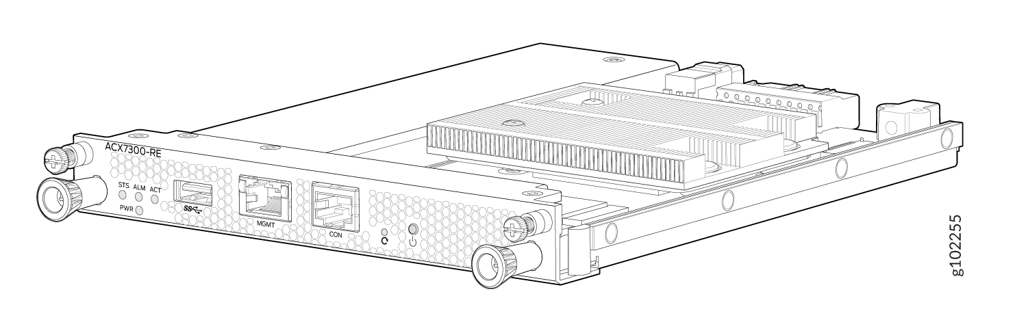
Each Routing Engine includes the following internal components:
-
CPU—High-performance 2.2-GHz Intel 4 Core ICX-D CPU
-
DRAM—2x32 GB DDR4 RAM
-
Solid-state drive (SSD)—One 100GB SATA SSD
Table 1 summarizes the physical specifications of the Routing Engine.
| Description | Value |
|---|---|
|
Height |
0.88 in. (2.23 cm) |
|
Width |
6.75 in. (17.74 cm) |
|
Depth |
8.33 in. (21.25 cm) |
|
Weight |
2.14 lbs (0.97 kg) |
Routing Engine Front Panel
Figure 2 shows the front panel of the ACX7332 Routing Engine.
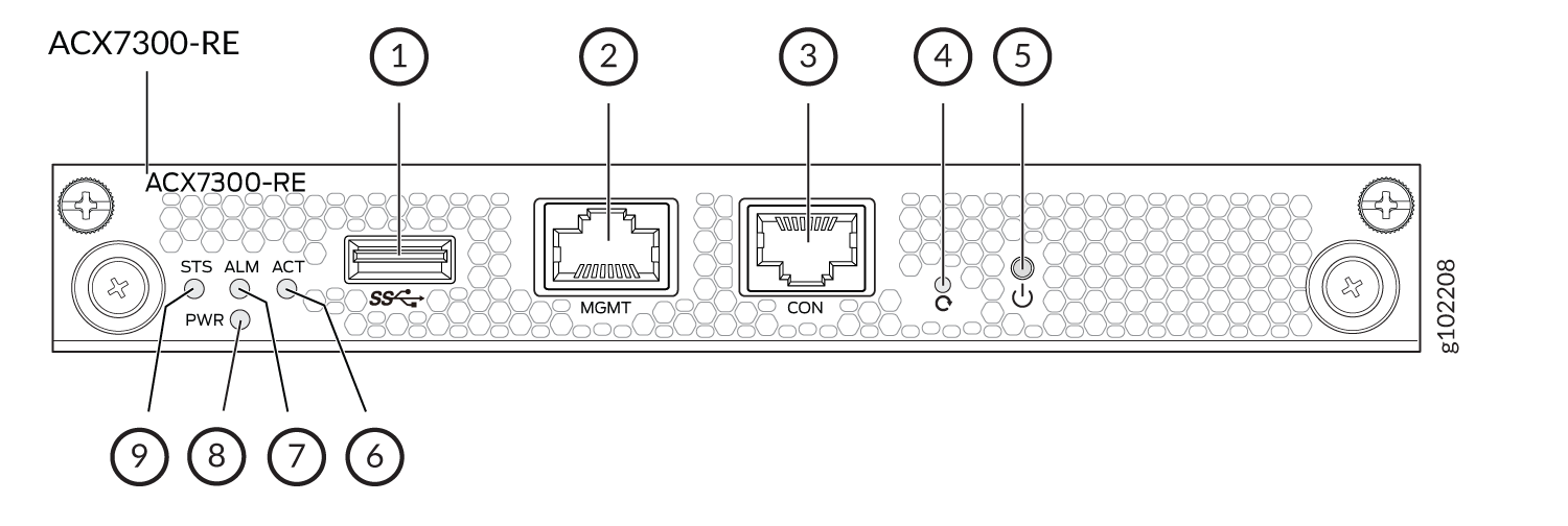
1 — USB port | 6 — ACT LED |
2 — Management (MGMT) port | 7 — ALM LED |
3 — Console (CON) port | 8 — PWR LED |
4 — Reset button | 9 — STS LED |
5 — Online/Offline button |
The Routing Engine ports with the indicated labels function as follows:
-
CON—Connects the Routing Engine to a system console through a serial cable with an RJ-45 connector.
-
MGMT—Connects the Routing Engine through an Ethernet connection to a management LAN (or any other device that plugs into an Ethernet connection) for out-of-band management. The port uses an autosensing RJ-45 connector to support 10-Mbps, 100-Mbps, or 1000-Mbps connections. Two small LEDs (an activity LED and a link LED) on the port indicate that the connection is in use.
The link LED is:
-
Green (steady) when the 1000-Mbps link is up.
-
Orange (steady) when the 100-Mbps link is up.
-
Off when the link is down.
-
Off and ACT LED is Yellow (blinking) when the 10-Mbps link is up.
The activity LED is:
-
Yellow (blinking) when traffic is passing through the port.
-
Off when link is down.
-
Yellow (steady) when traffic is not passing through the port.
Both activity and link LEDs are off when the link is down.
-
-
USB—Provides a removable media interface through which you can install Junos OS Evolved manually. Junos OS Evolved supports USB version 2.0 and later.
The following buttons are located on the Routing Engine:
-
RESET button—When pressed, reboots the Routing Engine as follows:
-
Short press reboots the Routing Engine.
-
When pressed for more than 10 seconds, the Routing Engine reboots with an option for BIOS recovery.
-
-
Online/Offline button—When the Routing Engine is offline and if the button is pressed (short press), the Routing Engine starts booting. When the Routing Engine is online and if the button is pressed for four seconds or more (long press), the Routing Engine shuts down.
Routing Engine LEDs
The LEDs—labeled STS, ALM, ACT, PWR—are located on the faceplate of the Routing Engine.
| LED | Color | State | Description |
|---|---|---|---|
|
PWR |
Green |
On steadily |
The Routing Engine is receiving adequate power. |
|
Red |
Blinking |
The Routing Engine is powered on but it has encountered a fault condition. |
|
|
Dark |
Off |
Power is disabled. |
|
|
STS |
Green |
On steadily |
The software is loaded and the Routing Engine is online. |
|
Green |
Blinking |
The system is loading the software. |
|
|
Green |
Blipping |
The system is powering up. |
|
|
Yellow |
Blinking |
The software is initialized and the Routing Engine has encountered an error condition. |
|
|
Dark |
Off |
The system is offline. |
|
|
ALM |
Dark |
Off |
There is no alarm. |
|
Red |
On steadily |
A major alarm has occurred. |
|
|
Amber |
On steadily |
A minor alarm has occurred. |
|
|
Amber and Red |
Blinking amber followed by blinking red |
Indicates the presence of a major and a minor alarm. |
|
|
ACT |
Green |
On steadily |
This Routing Engine is active. |
|
Dark |
Off |
The Routing Engine in in standby mode. |