ACX7100-32C Chassis
Management Panel of ACX7100-32C Routers
The management panel of ACX7100-32C routers is located on the front of the router along with the interface ports. Figure 1 shows the management panel components on an ACX7100-32C router.
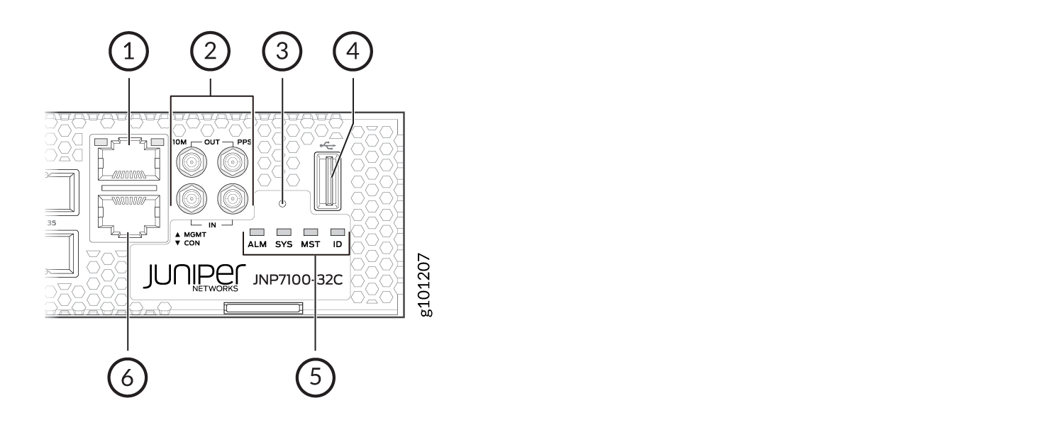
1 — Management (MGMT) port | 4 — USB port |
2 — 1-PPS and 10-MHz GPS input and output ports | 5 — Status LEDs |
3 — RESET button | 6 — Console (CON) port. |
The management panel on an ACX7100-32C router displays the router product number, and consists of the following components:
-
Status LEDs—ALM, SYS, MST, and ID LEDs.
-
Management (MGMT) port—10/100/1000BASE-T management port that uses an RJ-45 connector to connect to a management device for out-of-band management. See Connect an ACX7100-32C Router to a Network for Out-of-Band Management.
-
Console (CON) port—uses an RJ-45 connector to connect to a console management device.
-
USB port for image updates
-
Reset button to reset the device.
-
SMB connector ports that support 1-PPS and 10-MHz timing devices.
Management Port LEDs on ACX7100-32C Routers
The ACX7100-32C has one management port that has separate LEDs to indicate link status and link activity. The port is located on the management panel and is labeled MGMT. Figure 2 shows the location of the LEDs.
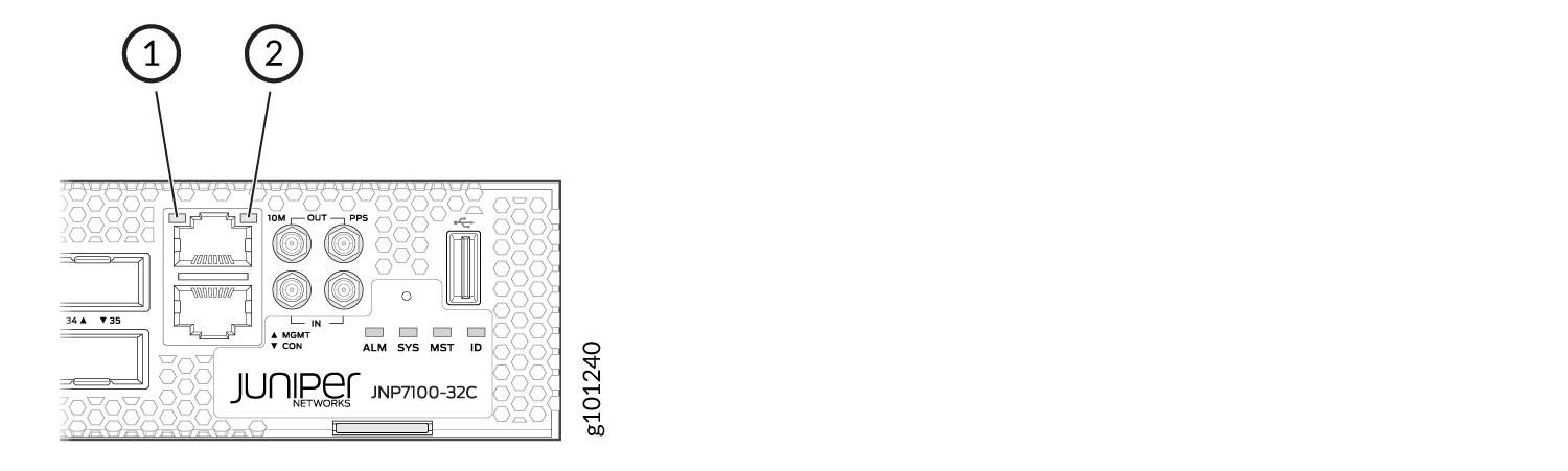
1 — Link activity LED (RJ-45) | 2 — Status LED (RJ-45) |
Table 1 describes the management port LEDs on ACX7100-32C routers.
|
LED |
Color |
State |
Description |
|---|---|---|---|
|
Link activity LED |
Green |
Blinking |
A link is established, and there is link activity. |
|
Status LED |
Unlit |
Off |
No link is established, or the port speed is 10Mbps. |
|
Yellow |
On steadily |
The port speed is 100 Mbps. |
|
|
Green |
On steadily |
The port speed is 1 Gbps. |
Port Panel of ACX7100-32C Routers
The port panel of an ACX7100-32C router has the following port configurations:
-
Thirty-two quad small form-factor pluggable (QSFP28) transceivers (ports 0 through 31) that operate at 100-Gbps speed when you use QSFP28 transceivers or at 40-Gbps speed when you use QSFP+ transceivers.
Note:You can configure port 31 as a 1-Gigabit SFP grandmaster port by using a QSA adapter to convert the QSFP28 port to a 1-Gigabit SFP port.
-
Four double density quad small-form factor pluggable (QSFP56-DD) ports (ports 32 through 35) that are configured as 400GbE ports by default.
The QSFP56-DD network ports support:
-
QSFP56-DD transceivers
-
QSFP28-DD transceivers
-
QSFP28 transceivers
-
QSFP+ transceivers
-
Active optical cables (AOC)
-
Direct attach copper (DAC) cables
-
At an ambient temperature greater than 40°C (at 6000 feet altitude above sea level), you can install only 100G transceivers in any of the QSFP56-DD ports.
See Guidelines for Using QDD-400G-ZR, QDD-400G-ZR-M, JCO400-QDD-ZR, and JCO400-QDD-ZR-M Transceivers before you install QDD-400G-ZR and QDD-400G-ZR-M transceivers.
Figure 3 shows the port panel on an ACX7100-32C router.
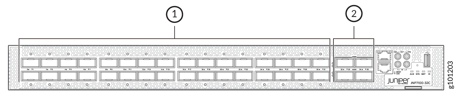
1 — 100GbE ports (32 QSFP28 ports) | 2 — 400GbE ports (4 QSFP56-DD ports) |
To understand all the potential restrictions and validate different port configurations on an ACX7100-32C router, use the Port Checker Tool.
Guidelines for Using QDD-400G-ZR, QDD-400G-ZR-M, JCO400-QDD-ZR, and JCO400-QDD-ZR-M Transceivers
Before you install the QDD-400G-ZR, QDD-400G-ZR-M, JCO400-QDD-ZR, and JCO400-QDD-ZR-M transceivers, you must update the temperature thresholds of the inlet sensors to facilitate an increase in fan speeds. This prevents the transceivers from powering off. We recommend that you update the temperature thresholds at ambient room temperature (23°C to 27°C).
Update the Temperature Thresholds
The following example requires you to navigate various levels in the configuration hierarchy. For information about navigating the CLI, see the CLI User Guide.
If the transceiver is already inserted when you apply the configuration, reseat the transceiver to bring it up properly.
To update the temperature thresholds, in configuration mode, perform the following steps on an ACX7100-32C device:
- Update the temperature thresholds for the
Main PCBLefttemperature sensor by executing the following commands:for QDD-400G-ZR and QDD-400G-ZR-M:
[edit]
user@host#set chassis cb 0 temperature-sensor "Main PCBLeft" temperature-threshold fans-on-full-speed 43
user@host#set chassis cb 0 temperature-sensor "Main PCBLeft" temperature-threshold fans-on-full-speed-if-failed-fan 43
user@host#set chassis cb 0 temperature-sensor "Main PCBLeft" temperature-threshold fans-on-intermediate-speed 26
user@host#set chassis cb 0 temperature-sensor "Main PCBLeft" temperature-threshold fans-to-normal-speed 21
for JCO400-QDD-ZR and JCO400-QDD-ZR-M:
[edit]
user@host#set chassis cb 0 temperature-sensor "Main PCBLeft" temperature-threshold fans-on-full-speed 30
user@host#set chassis cb 0 temperature-sensor "Main PCBLeft" temperature-threshold fans-on-full-speed-if-failed-fan 30
user@host#set chassis cb 0 temperature-sensor "Main PCBLeft" temperature-threshold fans-on-intermediate-speed 21
user@host#set chassis cb 0 temperature-sensor "Main PCBLeft" temperature-threshold fans-to-normal-speed 16
- Update the temperature thresholds for the
Main PCBRighttemperature sensor by executing the following commands:for QDD-400G-ZR and QDD-400G-ZR-M:
[edit]
user@host#set chassis cb 0 temperature-sensor "Main PCBRight" temperature-threshold fans-on-full-speed 51
user@host#set chassis cb 0 temperature-sensor "Main PCBRight" temperature-threshold fans-on-full-speed-if-failed-fan 51
user@host#set chassis cb 0 temperature-sensor "Main PCBRight" temperature-threshold fans-on-intermediate-speed 36
user@host#set chassis cb 0 temperature-sensor "Main PCBRight" temperature-threshold fans-to-normal-speed 31
for JCO400-QDD-ZR and JCO400-QDD-ZR-M:
[edit]
user@host#set chassis cb 0 temperature-sensor "Main PCBRight" temperature-threshold fans-on-full-speed 34
user@host#set chassis cb 0 temperature-sensor "Main PCBRight" temperature-threshold fans-on-full-speed-if-failed-fan 34
user@host#set chassis cb 0 temperature-sensor "Main PCBRight" temperature-threshold fans-on-intermediate-speed 25
user@host#set chassis cb 0 temperature-sensor "Main PCBRight" temperature-threshold fans-to-normal-speed 20
- Commit the configuration.
[edit]
user@host#commit
In the above example, the threshold values are updated to support the QDD-400G-ZR-M and JCO400- QDD-ZR-M transceivers. If you are not using the QDD-400G-ZR-M and JCO400-QDD-ZR-M transceivers, you will need to delete the changes made to the temperature thresholds. To do this, in configuration mode, perform the following steps:
-
Delete the Main PCBLeft and Main PCBRight temperature sensors.
[edit]
user@host#delete chassis cb 0 temperature-sensor "Main PCBLeft"
user@host#delete chassis cb 0 temperature-sensor "Main PCBRight"
-
Commit the configuration.
[edit]
user@host#commit
Verify the Updated Temperature Thresholds
You can verify the changes made to temperature thresholds by using any of the following methods:
-
In operational mode, run the
show chassis
                enhanced-temperature-thresholds
command to view the configured thresholds for all the sensors. -
In configuration mode, execute the following command:
user@host# show chassis cb 0
temperature-sensor "Main PCBLeft" {
    temperature-threshold {
        fans-to-normal-speed 21;
        fans-on-intermediate-speed 26;
        fans-on-full-speed 43;
        fans-on-full-speed-if-failed-fan 43;
    }
}
temperature-sensor "Main PCBRight" {
    temperature-threshold {
        fans-to-normal-speed 31;
        fans-on-intermediate-speed 36;
        fans-on-full-speed 51;
        fans-on-full-speed-if-failed-fan 51;
    }
}
Network Port LEDs on ACX7100-32C Routers
Each ACX7100-32C network port uses a single bicolored LED to indicate link status, activity on the link, or a fault condition. Figure 4 and Figure 5 show the location of the LEDs on an ACX7100-32C device.
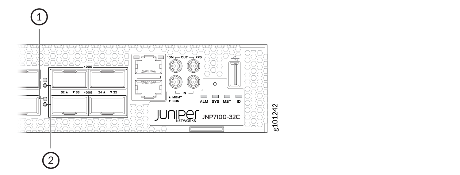
1 — Left port LED | 2 — Right port LED |
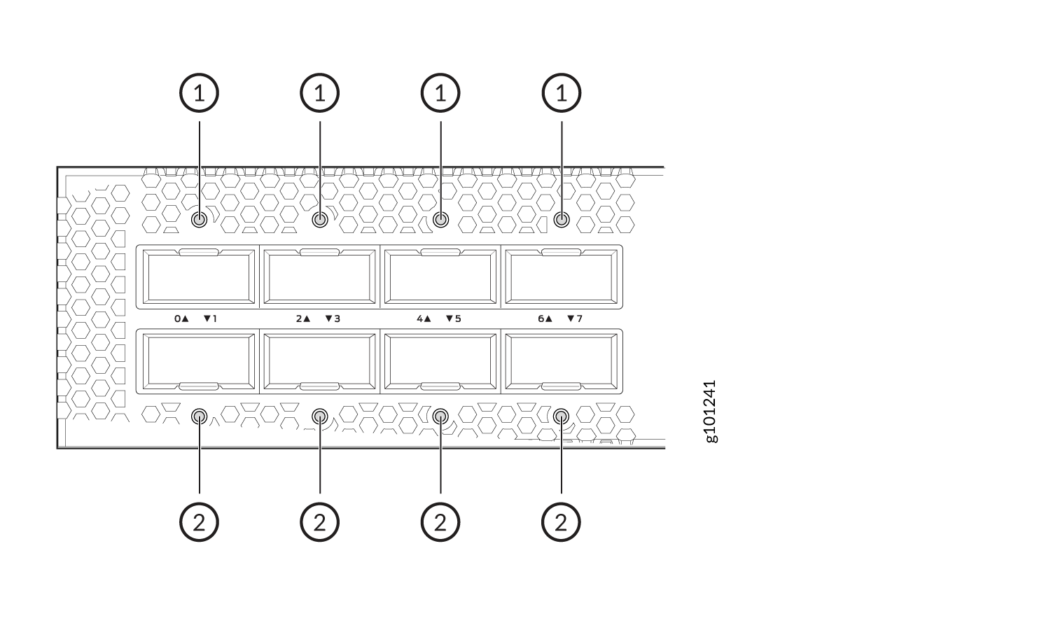
1 — Upper port LED | 2 — Lower port LED |
The number next to the LED indicates the port number to which the LED belongs. All network port LEDs behave the same. Table 2 describes the network port LEDs on ACX7100-32C routers, their colors and states, and the status that they indicate.
|
LED Color |
LED State |
Description |
|---|---|---|
|
Unlit |
Off |
The port is administratively disabled, there is no power, the link is down, or a transceiver is not present. |
|
Green |
On steadily |
A link is established, and all channels are up. |
|
Blinking |
The beacon function is enabled on the port. |
|
|
Amber |
On steadily |
One or more channels are up. At least one channel has activity, but not all connections are active. |
|
Red |
On steadily |
All channels are down. |
Chassis Status LEDs on ACX7100-32C Routers
The ACX7100-32C routers have four status LEDs that indicate the system status. You can find these LEDs to the right of the network ports (see Figure 6).
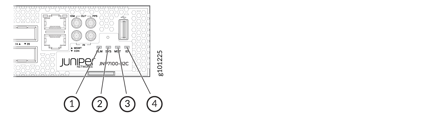
1 — ALM (Alarm) | 3 — MST (Primary) |
2 — SYS (System) | 4 — ID (Identification) |
Table 3 describes
the chassis status LEDs on ACX7100-32C routers, their colors and states,
and the status that they indicate. You can view the colors of the
three LEDs remotely through the CLI by issuing the operational mode
command show chassis led.
|
Name |
Color |
State |
Description |
|---|---|---|---|
|
ALM—Alarm LED |
Unlit |
Off |
The router is halted, or there is no alarm. |
|
Red |
On steadily |
A major hardware fault has occurred, such as a temperature alarm or power failure, and the router has halted (except during a single rotor failure in a fan module). Switch off power to the router and unplug the power cords. Correct any voltage or site temperature issues, and allow the router to cool down. Power on the router, and monitor the power supply and fan LEDs to determine where the error is occurring. |
|
|
Blinking |
Indicates the presence of a major and a minor alarm. |
||
|
Amber |
On steadily |
A minor alarm has occurred, such as a software error. Switch off power to the router and unplug the power cords. Power on the router, and monitor the status LEDs to ensure that Junos OS Evolved boots up properly. |
|
|
Blinking |
Indicates the presence of a major and a minor alarm. |
||
|
SYS—System LED |
Unlit |
Off |
The router is powered off or halted. |
|
Green |
On steadily |
Junos OS Evolved is loaded on the router. |
|
|
Blinking |
The device is loading the Software or the device is powering off. |
||
|
Slow blinking |
The device is powering up. |
||
|
MST—Primary LED |
Unlit |
Off |
The router is a linecard member. |
|
Green |
On steadily |
The router is a standalone router. |
|
|
ID—Identification LED |
Unlit |
Off |
The beacon feature is not enabled on the router. You
can enable this feature by using the |
|
Blue |
Blinking |
The beacon feature is enabled on the router. You can
disable this feature by using the |