ACX7024 and ACX7024X Chassis
Management Panel on ACX7024 and ACX7024X Routers
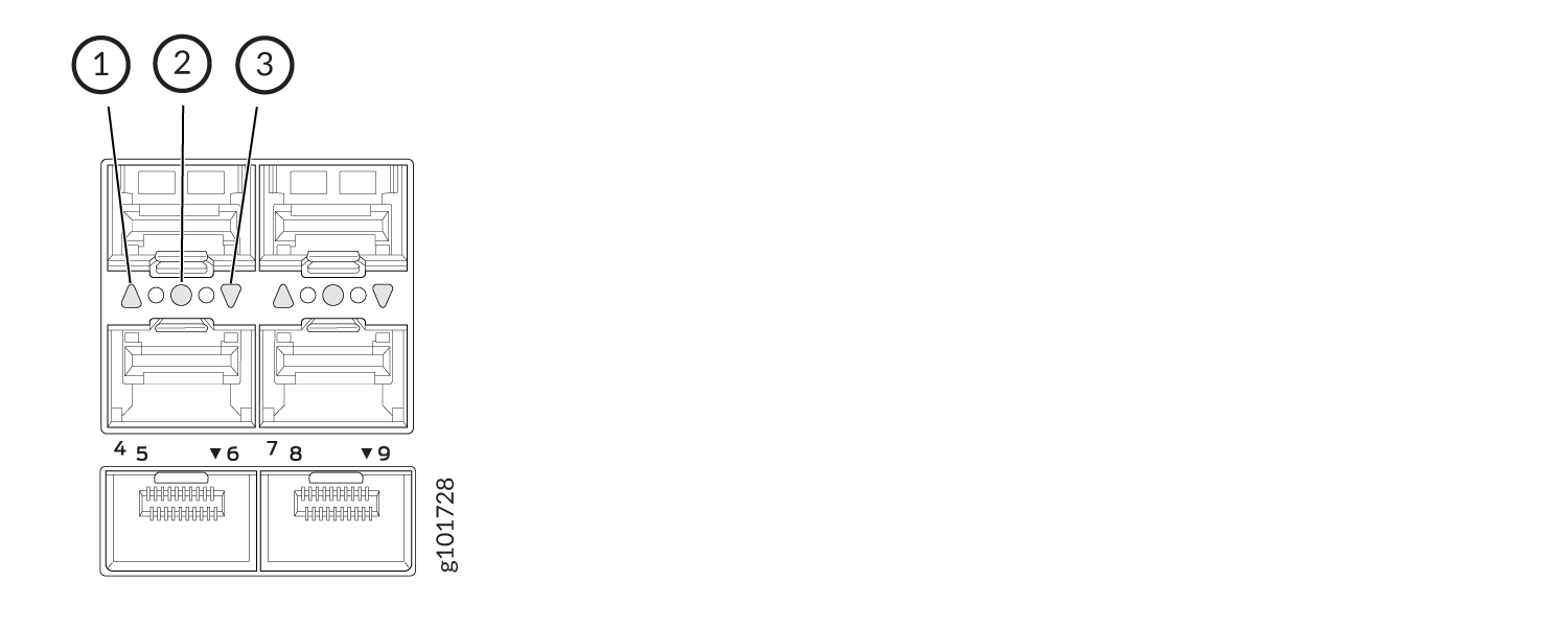
The management panel on ACX7024 and ACX7024X routers is located on the front of the router along with the interface ports. Figure 1 shows the management panel components on an ACX7024 and ACX7024X router.
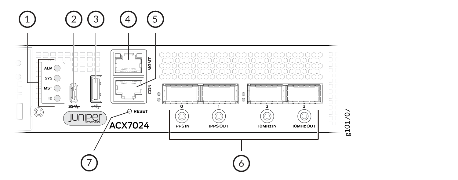
1 — Status LEDs | 5 — Console (CON) port |
2 — USB Type-C port | 6 — 1-PPS and 10-MHz GPS SMB connector ports |
3 — USB Type-A port | 7 — Reset (RESET) button |
4 — Management (MGMT) port |
The management panel on an ACX7024 and ACX7024X router displays the router product number, and it consists of the following components:
-
Status LEDs—ALM, SYS, MST, and ID LEDs.
-
USB Type-C port for external GNSS dongle support. The ACX7024 and ACX7024X routers supports the Furuno TB‑1 external GNSS receiver. To learn how to connect an ACX7024 or ACX7024X router to a Furuno TB-1 GNSS receiver, see Grand Master Clock Support Using External GNSS Receiver for ACX7024.
-
USB Type-A port for image updates.
-
Management (MGMT) port—10/100/1000BASE-T port that uses an RJ-45 connector to connect to a management device for out-of-band management.
-
SMB connector ports that support 1-PPS and 10-MHz timing devices.
-
Console (CON) port—Uses an RJ-45 connector to connect to a console management device. Additionally, you can use the CON port as a GPS time of day (TOD) port. To connect to both console and a TOD device simultaneously, you must use a breakout cable.
Note:If you connect to both console and a TOD device simultaneously using a breakout cable, make sure that you have not configured the
log-out-on-disconnectstatement at the[edit system ports console]hierarchy level. -
Reset (RESET) button to reset the router.
Management Port LEDs on ACX7024 and ACX7024X Routers
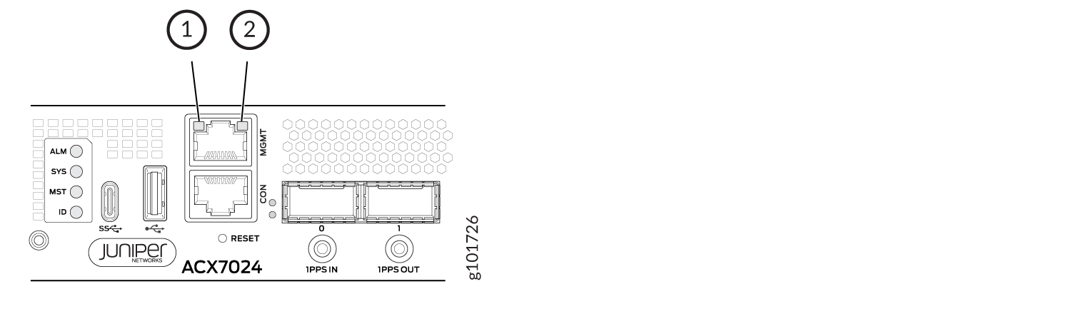
The ACX7024 and ACX7024X routers have a management port that has separate LEDs to indicate link status and link activity. The port is located on the management panel and is labeled MGMT. Figure 2 shows the location of the LEDs.
-
Link activity LED
-
Status LED
Table 1 describes the RJ-45 management port LEDs on ACX7024 routers.
|
LED |
Color |
State |
Description |
|---|---|---|---|
|
Link activity LED |
Unlit |
Off |
No link is established. |
|
Green |
Blinking |
A link is established, and there is link activity. |
|
|
Status LED |
Unlit |
Off |
No link is established, or the port speed is 10 Mbps. |
|
Amber |
On steadily |
The port speed is 100 Mbps. |
|
|
Green |
On steadily |
The port speed is 1 Gbps. |
Port Panel on ACX7024 and ACX7024X Routers
You can configure the ACX7024 and ACX7024X ports into 100GbE or 25GbE interfaces as follows:
-
Four 100GbE ports (ports 0 through 3) that support quad small form-factor pluggable 28 (QSFP28) transceivers. You can channelize these ports into four 25-Gbps interfaces using breakout cables and channelization configuration. These ports also support 40-Gbps speed, when you use QSFP+ optics. You can channelize these 40-Gbps ports into four 10-Gbps interfaces using breakout cables and channelization configuration.
-
Twenty-four 25GbE ports (ports 4 through 27) that operate at 25-Gbps speed with small form-factor pluggable 28 (SFP28) transceivers, 10-Gbps speed with SFP+ transceivers, or 1-Gbps speed with SFP transceivers.
Note:If you configure Precision Time Protocol (PTP), no interfaces are created for port 27 and the port is disabled.
For more information about valid port configurations on ACX7024 and ACX7024X routers, see Port Checker Tool.
Figure 3 shows the port panel on an ACX7024 and ACX7024X router.
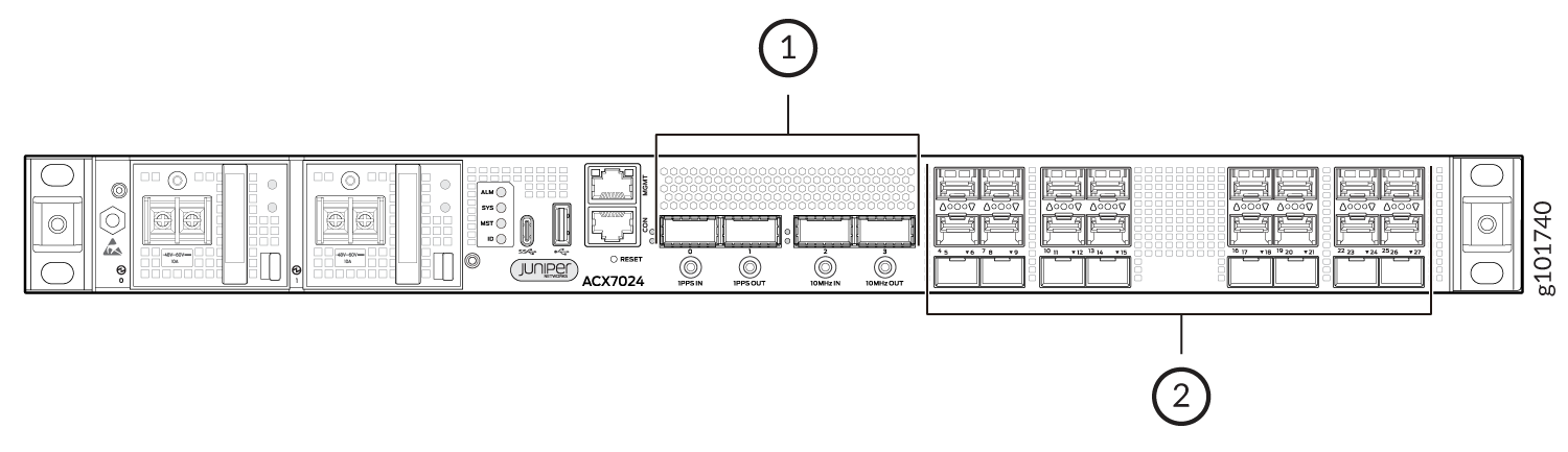
1 — Four 100GbE QSFP28 ports | 2 — Twenty-four 25GbE/10GbE/1GbE SFP28 ports |
Network Port LEDs on ACX7024 and ACX7024X Routers
Each ACX7024 and ACX7024X network port has a single LED to indicate link status, activity on the link, or a fault condition. Figure 4 and Figure 5 show the location of the LEDs on an ACX7024 and ACX7024X router.
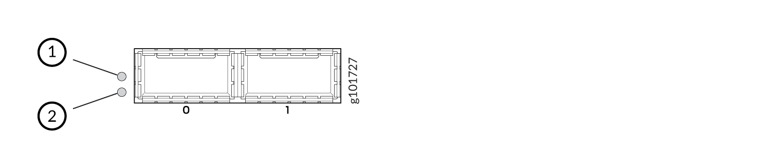
1 — Left-port LED | 2 — Right-port LED |
1 — Upper-port LED | 3 — Lower-port LED |
2 — Middle-port LED |
Table 2 describes the network port LEDs on the ACX7024 and ACX7024X routers, their colors and states, and the status that they indicate.
|
LED Color |
LED State |
Description |
|---|---|---|
|
Unlit |
Off |
There is no power, the link is down, or a transceiver is not present. |
|
Green |
On steadily |
A link is established, and all channels are up. |
|
Blinking |
The beacon function is enabled on the port. |
|
|
Amber |
On steadily |
The port is disabled in the CLI. |
|
Red |
On steadily |
All channels are down. |
Chassis Status LEDs on ACX7024 and ACX7024X Routers
Each ACX7024 and ACX7024X router has four status LEDs that indicate the system status. You can find these LEDs to the left of the USB ports (see Figure 6).

1 — ALM (Alarm) | 3 — MST (Primary) |
2 — SYS (System) | 4 — ID (Identification) |
Table 3 describes the chassis status LEDs on an ACX7024 and ACX7024X router, their colors
and states, and the status that the colors indicate. You can view the colors of the LEDs
remotely through the CLI by running the operational mode command show chassis
led.
|
Name |
Color |
State |
Description |
|---|---|---|---|
|
ALM—Alarm LED |
Unlit |
Off |
The router is halted, or there is no alarm. |
|
Red |
On steadily |
A major hardware fault has occurred, such as a temperature alarm or power failure, and the router has halted. Switch off power to the router and unplug the power cords. Correct any voltage or site temperature issues, and allow the router to cool down. Power on the router, and monitor the power supply LEDs to determine where the error is occurring. |
|
|
Yellow |
On steadily |
A minor alarm has occurred, such as a software error. Switch off power to the router and unplug the power cords. Power on the router, and monitor the status LEDs to ensure that Junos OS Evolved boots up properly. |
|
| Red and Yellow |
Blinking |
Indicates the presence of a major and a minor alarm. |
|
|
SYS—System LED |
Unlit |
Off |
The router is powered off or halted. |
|
Green |
On steadily |
Junos OS Evolved is loaded on the router. |
|
|
Blinking |
The device is loading the software or the device is powering off. |
||
|
Slow blinking |
The device is powering up. |
||
|
MST—Primary LED |
Green |
On steadily |
The router is a standalone router. |
|
ID—Identification LED |
Unlit |
Off |
The beacon feature is not enabled on the router. You can enable this feature by
using the |
|
Blue |
Blinking |
The beacon feature is enabled on the router. You can disable this feature by using
the |