ON THIS PAGE
Step 1: Begin
In this guide, we provide a simple, three-step path, to quickly get you up and running with your new Juniper Networks® ACX7024 Cloud Metro Router. We’ve simplified and shortened the installation and configuration steps to make it easy for you to install a DC-powered ACX7024 in a rack, power it up, and configure basic settings. For instructions on installing AC-powered ACX7024, see the ACX7024 Hardware Guide.
Meet the ACX7024
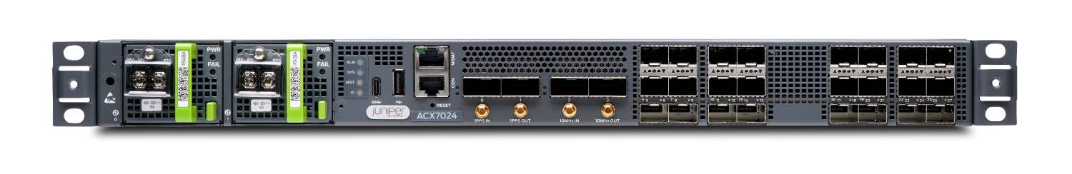
The ACX7024 Cloud Metro Router is a high-performance access router that addresses the growing demands of metro applications. With a compact 1‐U form factor, temperature-hardened design, and advanced timing features, the ACX7024 is well suited to support Ethernet business services, residential access, and 5G mobile deployments.
The ACX7024 provides 1GbE to 100GbE port flexibility and a switching capacity of 360 Gbps. It runs Junos OS Evolved and provides several capabilities that include support for the latest protocol and traffic engineering technologies, enhanced security, and precision timing for mobile backhaul applications.
Install the ACX7024
Along with your ACX7024 router, you’ll also find:
-
Documentation roadmap card
-
Two-post rack mounting brackets that are preinstalled on the router
-
Two #10-32 grounding screws to secure the grounding lug
-
An LCD6 2-hole grounding lug
What Else Do I Need?
-
Someone to help you secure the router to the rack
-
An electrostatic discharge (ESD) grounding wrist strap
-
Four rack mount screws appropriate for your rack to secure the router to the rack
-
A #2 Phillips (+) screwdriver
-
A management host such as a laptop or desktop PC
-
A serial-to-USB adapter (if your laptop or desktop PC doesn’t have a serial port)
-
A grounding cable: 6 AWG, 90°C stranded copper wire
-
A 12 AWG and 75°C temperature-rated or 14 AWG and 90°C temperature-rated stranded copper wire to connect the DC source to the router.
-
A customer-site 2-pole circuit breaker rated for 30A and 80V, or as required by local electrical code.
Rack It
Before you start the installation, be sure to review the General Safety Guidelines and Warnings.
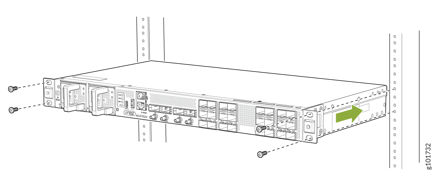
Here’s how to install the ACX7024 in a two-post rack:
-
Lift the ACX7024 router and position it in the rack. Line up the bottom
hole in each mounting bracket with a hole in each rack rail, making sure the
ACX7024 router is level.
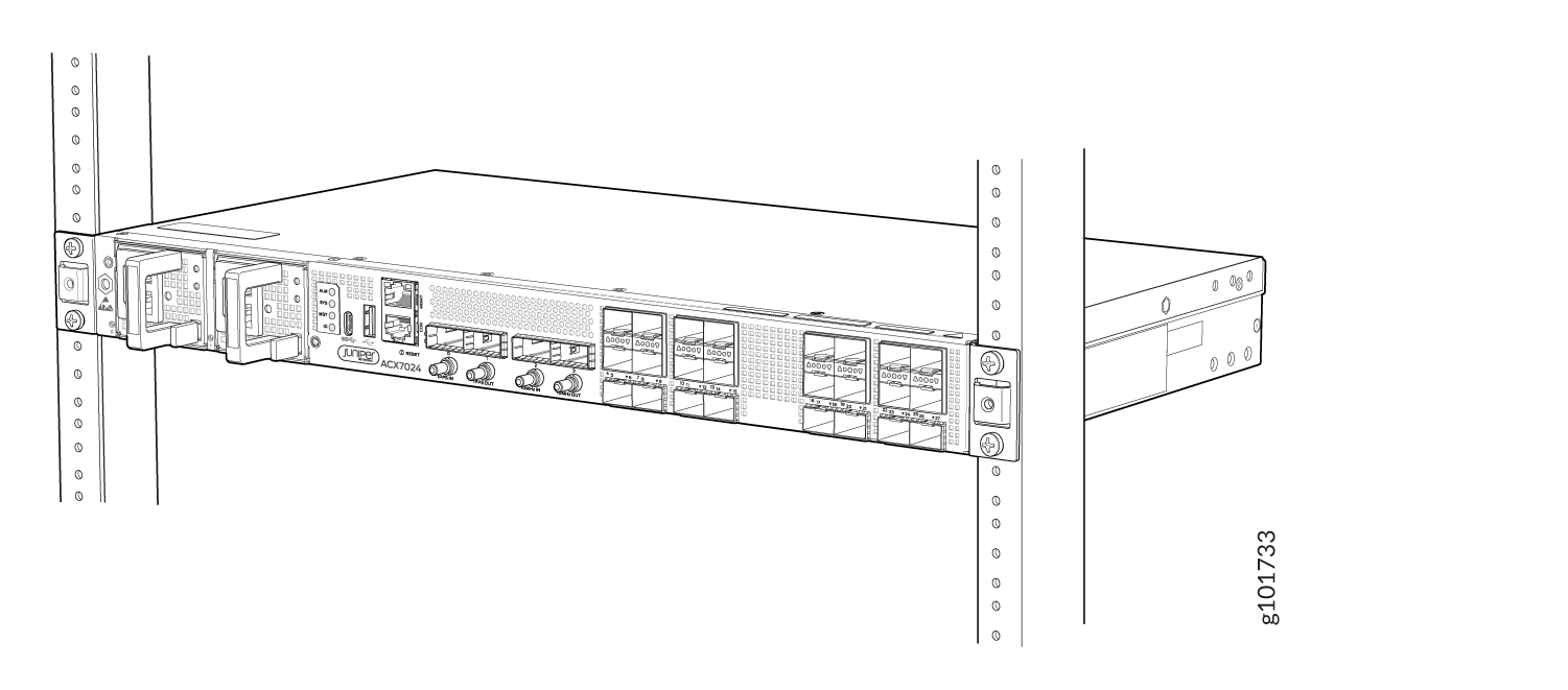
-
Check to see that the mounting screws on each side of the rack are lined up
and the router is level.
Power On
Now that you’ve installed your ACX7024 in the rack, let's connect it to power.
The ACX7024 supports DC power supplies that are pre-installed at the factory.
The connection between each power source and power supply module must include a circuit breaker. We recommend that you use a customer-site 2-pole circuit breaker rated for 30A and 80V, or as required by local electrical code.
Do not connect two sources to a single power supply module because doing so can potentially cause circulating current in feed wires whenever there is any difference in the voltage of the two sources.
The ACX7024 router operates with a DC power supply module that has a single, non-redundant, feed input. For source redundancy, you'll need to install two DC power supplies in the ACX7024. Connect source (A) to one power supply module and source (B) to the second power supply module. This configuration provides the commonly deployed A/B feed redundancy for the system.
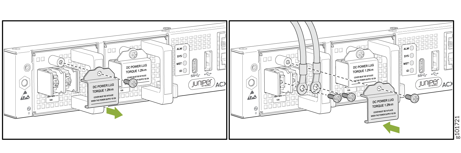
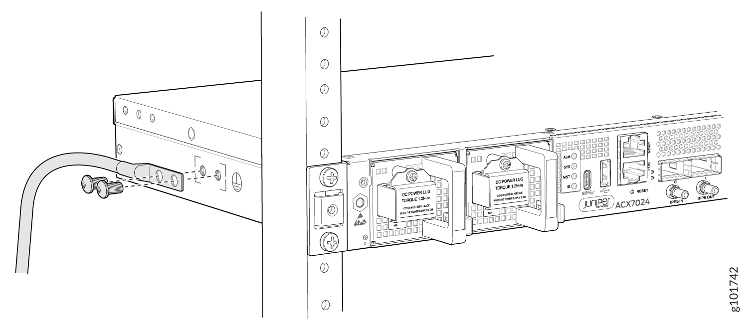
To meet safety and electromagnetic interference (EMI) requirements and to ensure proper operation, you'll need to properly ground the router before connecting it to power. Have a licensed electrician attach the cable lug to the grounding cable.
-
Place the grounding cable lug over the grounding points on the side of the
chassis, and secure it with the grounding screws. Apply 2.5 N-m of torque to
the grounding screws.
-
Close the input circuit breaker.
Note:
The switch powers on as soon as you connect it to power.