ON THIS PAGE
Antenna Cable Specifications
Antenna Cable Specifications
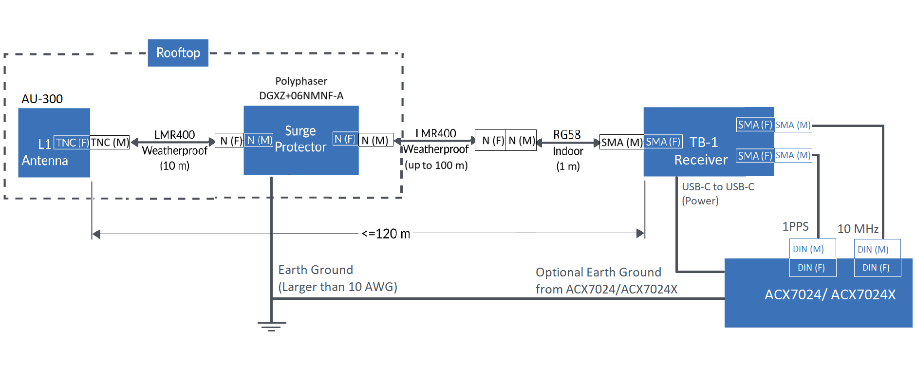
The following topology (Figure 1) depicts the antenna cable connections with connector types. Use this topology as an example to install the antenna cables.
 Juniper has tested
this topology with the following cables:
Juniper has tested
this topology with the following cables:
-
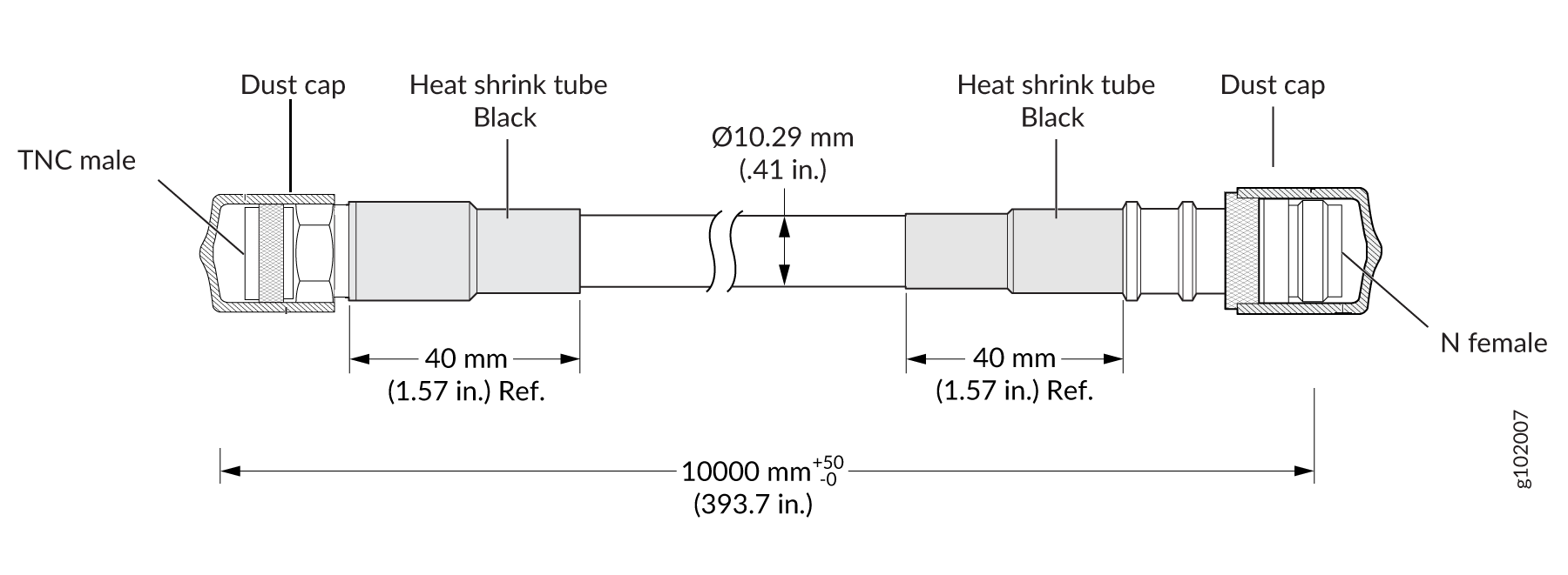
LMR400 (10-m segment) from TE Connectivity (Part number: CD-2430293). For more information, see LMR400 (10-m Segment) Cable Specifications.
-
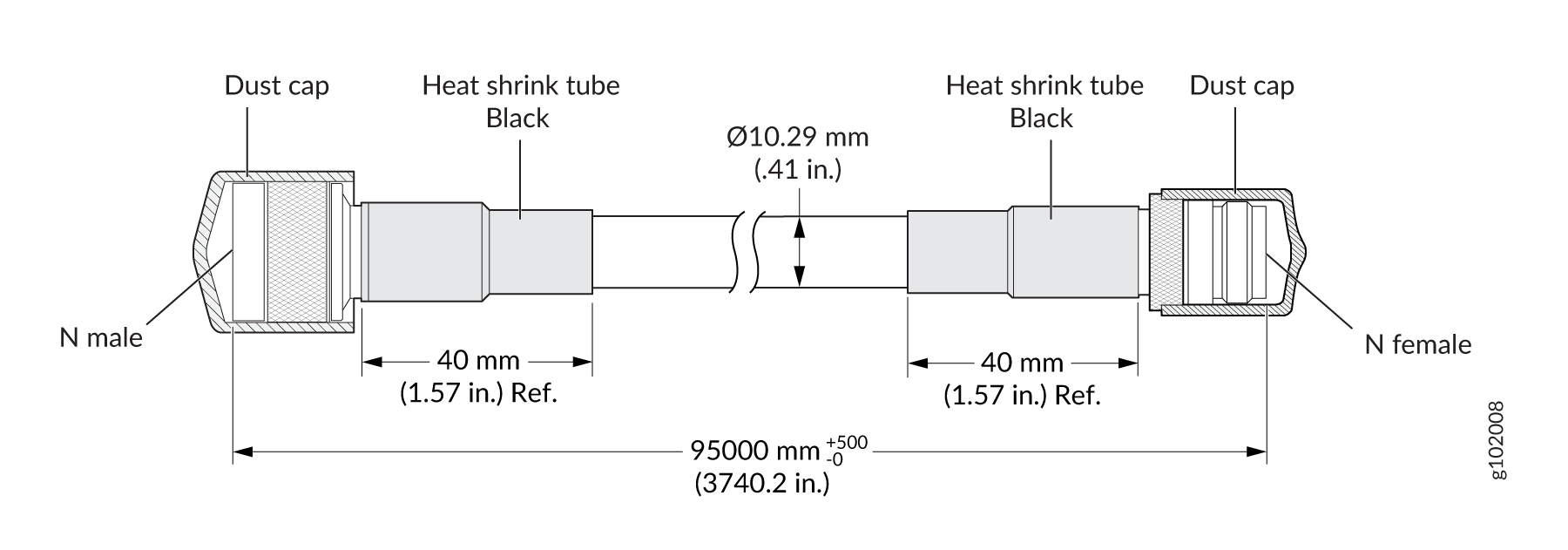
LMR400 (95-m segment) from TE Connectivity (Part number: CD-2430295). For more information, see LMR400 (95-m Segment) Cable Specifications.
Note:The cable length can be less than or equal to 95 m.
-
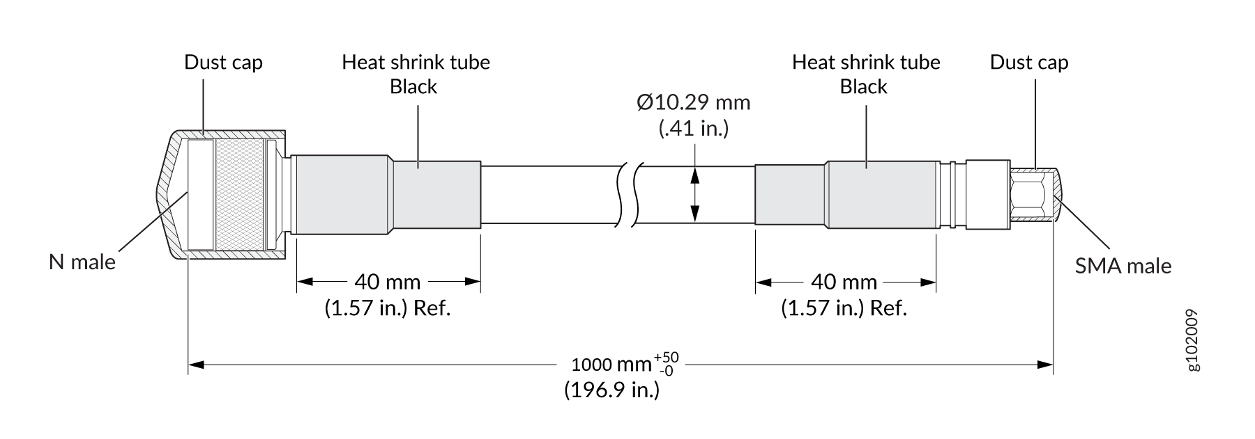
RG-58 (1-m segment) from TE Connectivity (Part number: CD-2430297). For more information, see RG-58 (1-m Segment) Cable Specifications.
You must ensure that you install a surge protector to protect the GNSS receiver from lightning surges. The surge protector next to the outdoor antenna must be a safety-certified antenna surge protector (certified to UL 497B or its IEC equivalent). The topology shown in Figure 1 uses a Polyphaser surge protector. For more information about the Polyphaser surge protector, see Type N M/F Coaxial RF Surge Protector.
You must ensure that the surge protector is grounded. To ground the Polyphaser surge protector, use a 10 AWG to 12 AWG grounding wire. For more information about grounding the surge protector, see GX, VHF, VUF Series Mounting & Grounding.
The following sections describe the antenna cable specifications:
- LMR400 (10-m Segment) Cable Specifications
- LMR400 (95-m Segment) Cable Specifications
- RG-58 (1-m Segment) Cable Specifications
LMR400 (10-m Segment) Cable Specifications
|
Electrical Characteristics |
|
|---|---|
|
Impedance |
50 Ω |
|
Frequency |
DC-3GHz |
|
Voltage Rating |
335 Vrms |
|
Dielectric Withstanding Voltage |
> 1000 V |
|
Insulation Resistance |
> 5000 MΩ |
LMR400 (95-m Segment) Cable Specifications
|
Electrical Characteristics |
|
|---|---|
|
Impedance |
50 Ω |
|
Frequency |
DC-3GHz |
|
Voltage Rating |
335 Vrms |
|
Dielectric Withstanding Voltage |
> 1000 V |
|
Insulation Resistance |
> 5000 MΩ |
RG-58 (1-m Segment) Cable Specifications
|
RG58 |
|
|---|---|
|
Impedance |
50 ± 2 Ω |
|
Capacitance |
100 pF/m |
|
Velocity Ratio |
66 % |
|
Resistance |
Inner Conductor- 36, 5 Ω/Km Braid- 14 Ω/Km |
| Tension |
Sheath and Spark testing- 4,0 kV |
Cabling Guidelines
Follow these guidelines when you install cables:
-
Ensure that the GNSS dongle can track the satellites and can acquire a lock.
-
Examine the cable end points and connectors for any bends or damage.
-
Check the electrical continuity of the cable for both inner and outer conductors.
-
Check for any electrical short in cables.
-
Inspect the cable outer sheath for any damage.