Fast Track to Rack Installation and Power
This procedure guides you through the steps to install the ACX7020 router in a rack and connect it to power.
Install an ACX7020 Router in a Rack
You can install a Juniper Networks® ACX7020 Cloud Metro router into a 19-inch, 21-inch, or 23-inch two-post rack or a cabinet. We’ll walk you through the steps to install an AC-powered ACX7020 router in a 19-inch two-post rack.
Before you install, review the following:
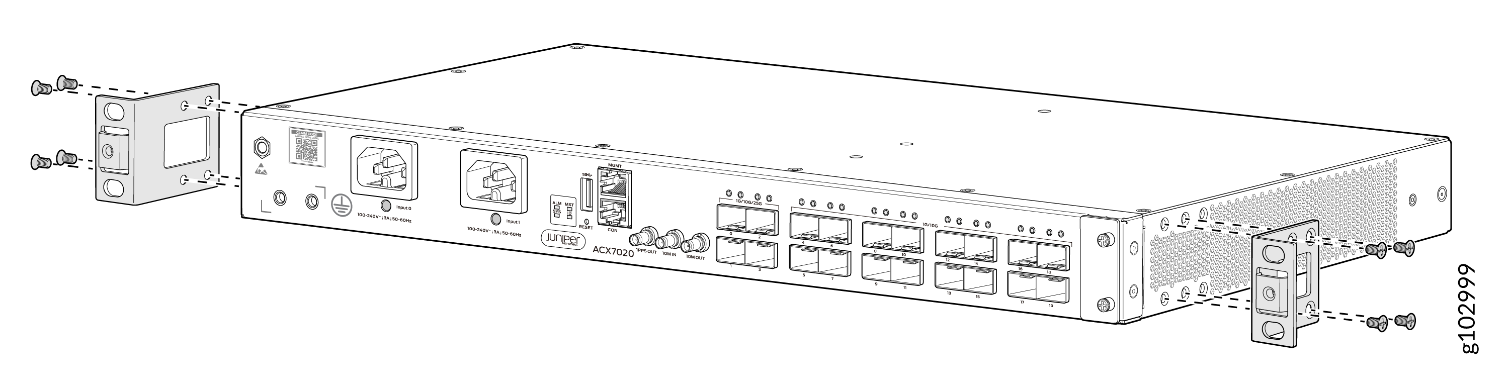
To mount an ACX7020 router on two posts of a rack:
-
Align the holes in the front-mounting brackets with the holes on the side
of the chassis.
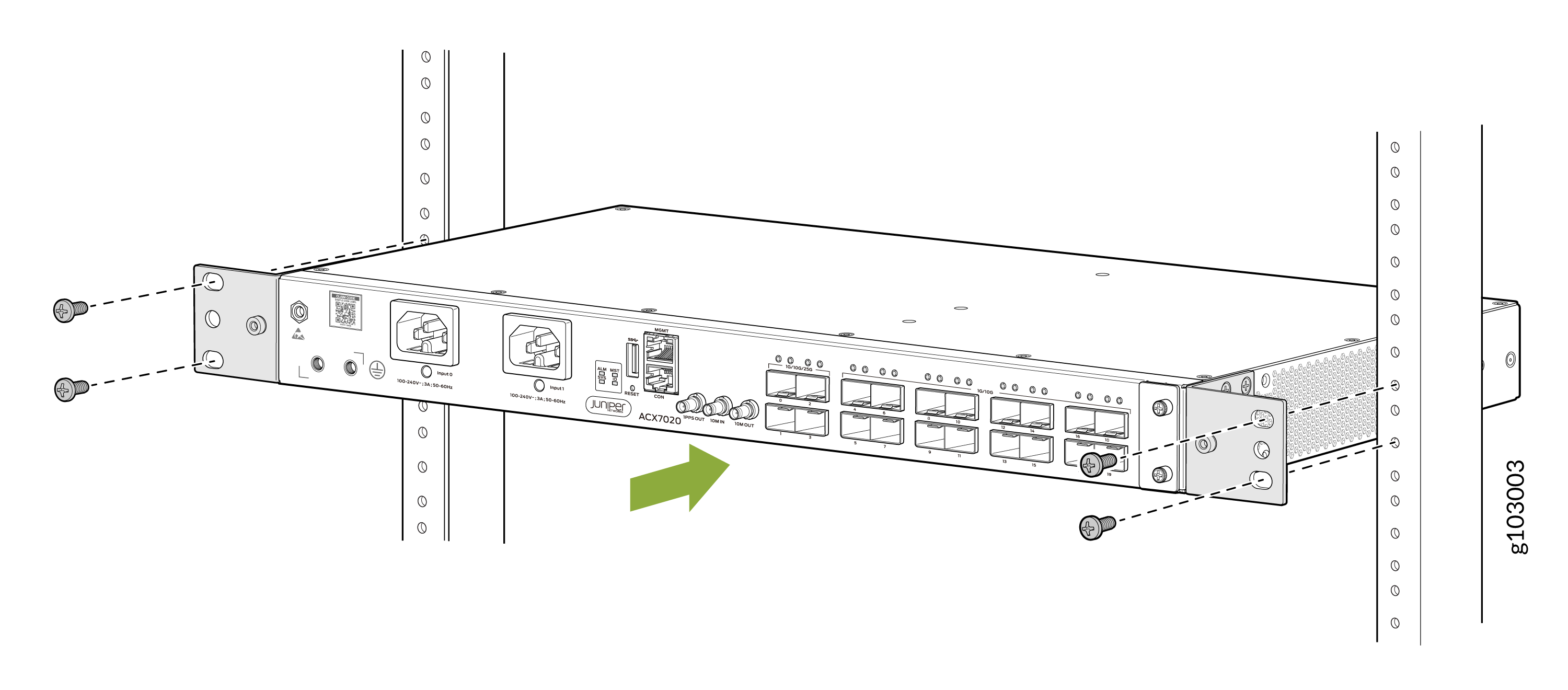
-
Lift the router and position it in the rack. Line up the top and bottom
holes in each mounting bracket with the holes in each rack rail, making sure
the router is level.
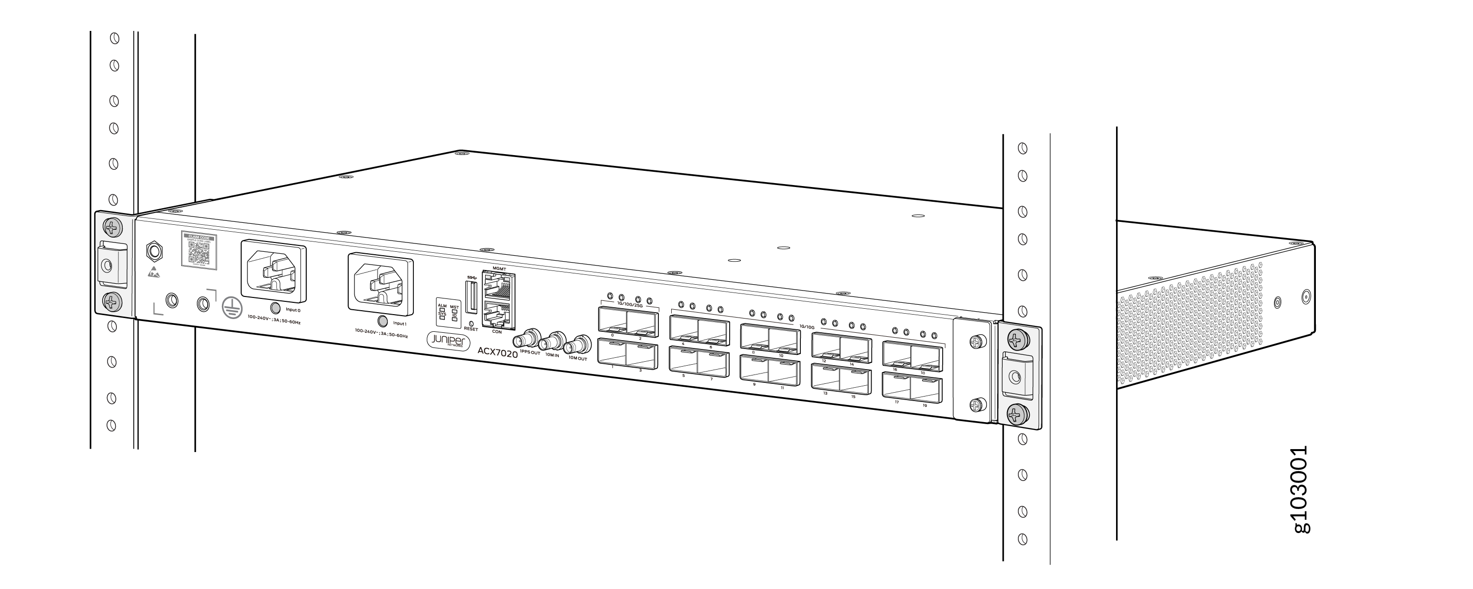
-
Check to see that the mounting screws on each side of the rack are aligned
and the router is level.
Connect to Power
To connect the ACX7020 router to AC power, perform the following steps:
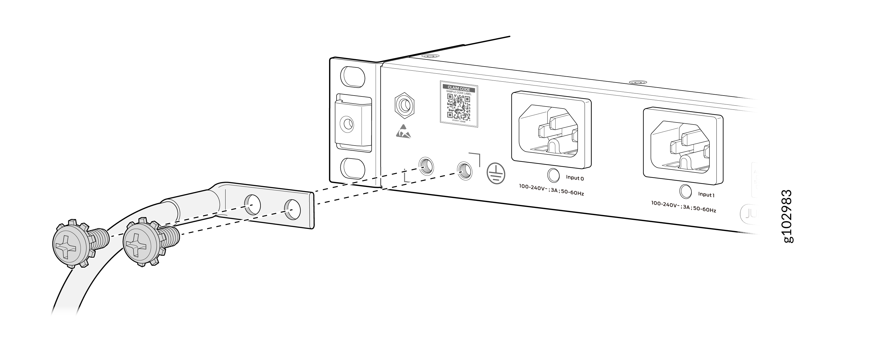
Connect Earth Ground to ACX7020 Routers
To ground the ACX7020 router:
-
Secure the grounding cable lug to the chassis grounding points using
two M5 x 10 mm grounding screws (provided).
Connect AC Power to ACX7020 Routers
Ensure that you have a power cord appropriate for your geographical location available to connect AC power to the router.
Before you begin connecting AC power to the router:
-
Ensure that you have taken the necessary precautions to prevent electrostatic discharge (ESD) damage (see Prevention of Electrostatic Discharge Damage).
-
Ensure that you have connected the router chassis to earth ground.
CAUTION:Before you connect power to the router, a licensed electrician must attach a cable lug to the grounding and power cables that you supply. A cable with an incorrectly attached lug can damage the router (for example, by causing a short circuit).
To meet safety and electromagnetic interference (EMI) requirements and to ensure proper operation, you must connect the chassis to earth ground before you connect it to power. Under all circumstances, use the protective grounding terminal on the router chassis to connect to the earth ground. The router gains additional grounding when you plug the power supply module (PSM) in the router to a grounded AC power outlet by using the AC power cord appropriate for your geographical location.
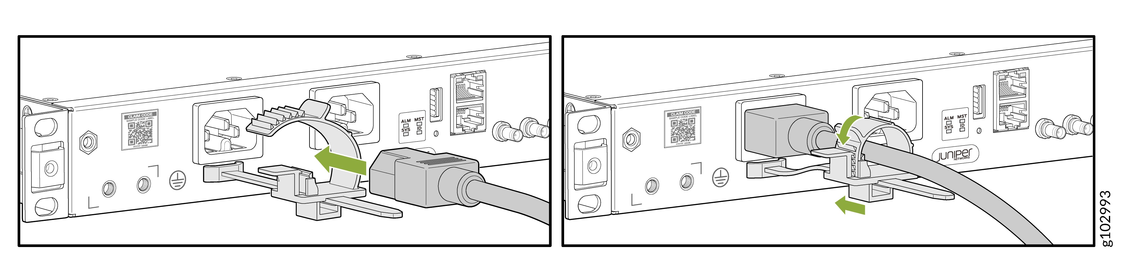
To connect AC power to an ACX7020 router:
-
Insert the power cord coupler firmly into the inlet.