Connect ACX7020 to Power
Learn how to ground the ACX7020 Router and connect it to AC and DC power.
Connect Earth Ground to ACX7020 Routers
Before you begin to connect the router to earth ground, ensure that you have the following parts and tools available:
- Grounding cable (yellow green)—6 AWG, 90 ºC wire, or as permitted by the local code (not provided).
- Grounding lug for your grounding cable—Panduit LCD6-14AF right angle lug or equivalent (provided).
- Two M5x10 screws for fastening the 2-hole lug to the system (provided).
- A Phillips (+) screwdriver, number 2 (not provided)
- An electrostatic discharge (ESD) grounding wrist strap (not provided)
To meet safety and electromagnetic interference (EMI) requirements and to ensure proper operation, you must ground the router properly before connecting power.
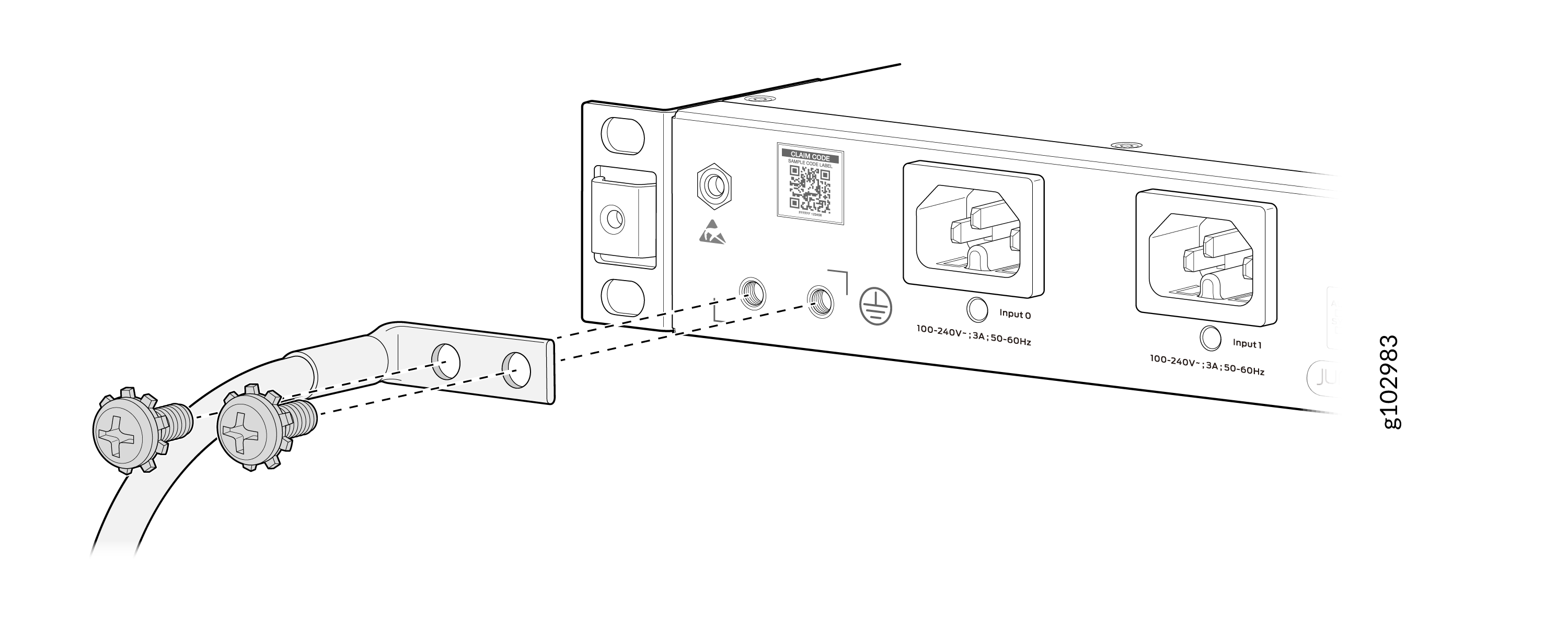
You must install the ACX7020 in a restricted-access location and ensure that the chassis is always properly grounded. The ACX7020 has a two-hole protective grounding terminal provided on the chassis. We recommend that you use this protective grounding terminal as the preferred method for grounding the chassis regardless of the power supply configuration. However, if additional grounding methods are available, you can also use those methods. For example, you can use the grounding wire in the AC power cord or use the grounding terminal or lug on a DC power supply. This tested system meets or exceeds all applicable EMC regulatory requirements with the two-hole protective grounding terminal.

1 — Grounding point |
To ground the ACX7020 router:
-
Secure the grounding cable lug to the chassis grounding points using two M5
x 10 mm grounding screws (provided).
Figure 2: Connect the Grounding Cable to the ACX7020 Router
Connect AC Power to ACX7020 Routers
Ensure that you have a power cord appropriate for your geographical location available to connect AC power to the router.
Before you begin connecting AC power to the router:
-
Ensure that you have taken the necessary precautions to prevent electrostatic discharge (ESD) damage (see Prevention of Electrostatic Discharge Damage).
-
Ensure that you have connected the router chassis to earth ground.
CAUTION:Before you connect power to the router, a licensed electrician must attach a cable lug to the grounding and power cables that you supply. A cable with an incorrectly attached lug can damage the router (for example, by causing a short circuit).
To meet safety and electromagnetic interference (EMI) requirements and to ensure proper operation, you must connect the chassis to earth ground before you connect it to power. Under all circumstances, use the protective grounding terminal on the router chassis to connect to the earth ground. The router gains additional grounding when you plug the PSM in the router to a grounded AC power outlet by using the AC power cord appropriate for your geographical location.
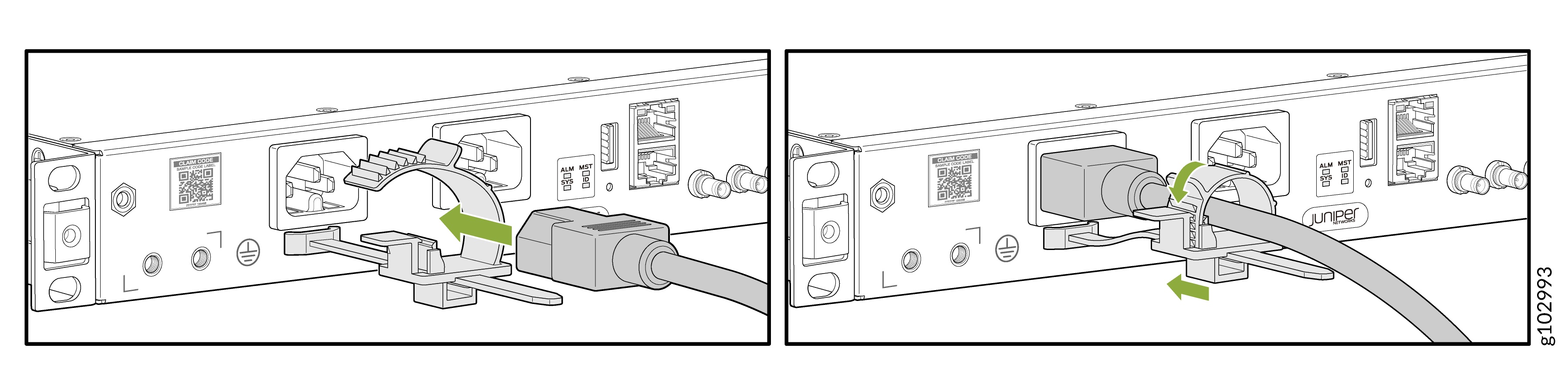
To connect AC power to an ACX7020 router:
-
Insert the power cord coupler firmly into the inlet.
Figure 3: Connect an AC Power Cord to an ACX7020 Router
Connect DC Power to ACX7020 Routers
Before you begin connecting DC power to the router:
-
Ensure that you have taken the necessary precautions to prevent electrostatic discharge (ESD) damage (see Prevention of Electrostatic Discharge Damage).
-
Ensure that you have connected the router chassis to earth ground.
CAUTION:Before you connect power to the router, a licensed electrician must attach a cable lug to the grounding and power cables that you supply. A cable with an incorrectly attached lug can damage the router (for example, by causing a short circuit).
To meet safety and electromagnetic interference (EMI) requirements and to ensure proper operation, you must connect the chassis to earth ground before you connect it to power. Under all circumstances, use the protective grounding terminal on the router chassis to connect to the earth ground.
Ensure that you have the following parts and tools available:
-
14 AWG and 75 °C temperature rating cables (not provided)
-
An electrostatic discharge (ESD) grounding wrist strap (not provided)
-
A torque-controlled screwdriver (not provided)—A torque of 0.8–1 Nm is required to tighten the screws to the terminal block.
To connect DC power to an ACX7020 router:
-
Install heat-shrink tubing insulation around the power
cables.
To install heat-shrink tubing:
-
Slide the tubing over the portion of the cable where it is attached to the lug barrel. Ensure that tubing covers the end of the wire and the barrel of the lug attached to it.
-
Shrink the tubing with a heat gun. Ensure that you heat all sides of the tubing evenly so that it shrinks around the cable tightly.
Figure 4 shows the steps to install heat-shrink tubing.
Note:Do not overheat the tubing.
Figure 4: Install Heat-Shrink Tubing
-
-
The DC PSM has a negative terminal and a positive terminal for connecting
the DC power cables labeled negative (-) and positive (+). Secure power
source cables to the PSMs by screwing the ring lugs attached to the cables
to the appropriate terminals by using the screw from the terminals
-
Secure the positive (+) DC source power cable lug to the positive terminal.
-
Secure the negative (–) DC source power cable lug to the negative terminal.
CAUTION:You must ensure that power connections maintain the proper polarity. The power source cables might be labeled (+) and (–) to indicate their polarity. There is no standard color coding for DC power cables. The color coding used by the external DC power source at your site determines the color coding for the leads on the power cables that attach to the terminal studs on each PSM.
Figure 5: Connect DC Power Cable to an ACX7020 Router
-