ACX7020 Chassis
Learn about the ACX7020 router chassis.
ACX7020 Chassis Description
The router chassis is a rigid sheet metal structure that houses all the router components. The ACX7020 router has a 1-U fixed form factor with two fixed power supply modules (PSMs) that support AC or DC power. The ACX7020 router cooling system consists of an air filter and a fixed fan tray with three fans that provide side-to-side cooling.
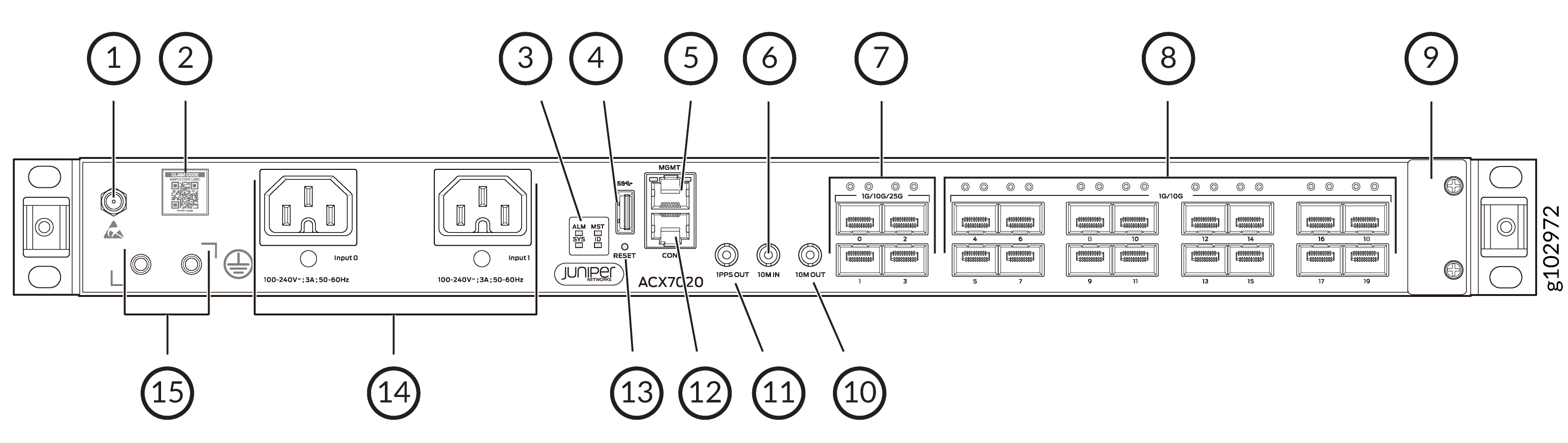
1 — ESD point | 9 — Air filter |
2 — Claim code label | 10 — 10M OUT port |
3 — Status LEDs | 11 — 1PPS OUT port |
4 — USB 3.0 Type-A port | 12 — Console (CON) port |
5 — Management (MGMT) port | 13 — Reset (RESET) button |
6 — 10M IN port | 14 — AC PSMs |
7 — 4 SFP28 ports | 15 — Grounding point |
8 — 16 SFP ports |
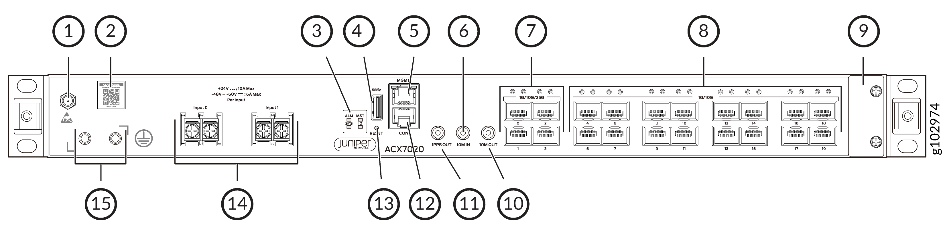
1 — ESD point | 9 — Air filter |
2 — Claim code label | 10 — 10M OUT port |
3 — Status LEDs | 11 — 1PPS OUT port |
4 — USB 3.0 Type-A port | 12 — Console (CON) port |
5 — Management (MGMT) port | 13 — Reset (RESET) button |
6 — 10M IN port | 14 — DC PSMs |
7 — 4 SFP28 ports | 15 — Grounding points |
8 — 16 SFP ports |
Port Panel on ACX7020 Routers
The port panel of an ACX7020 router has the following port configurations:
-
Four 25GbE small form-factor pluggable 28 (SFP28) ports (port 0 through 3) that operate at 25-Gbps speed with SFP28 transceivers, 10-Gbps speed with SFP+ transceivers or 1-Gbps speed with SFP transceivers.
-
Sixteen 10GbE small form-factor pluggable (SFP+) ports (port 4 through 19) that operate at 10-Gbps speed with SFP+ transceivers, or 1-Gbps speed with SFP transceivers.
If you configure Precision Time Protocol (PTP), no interfaces are created for port 19 and the port is disabled.
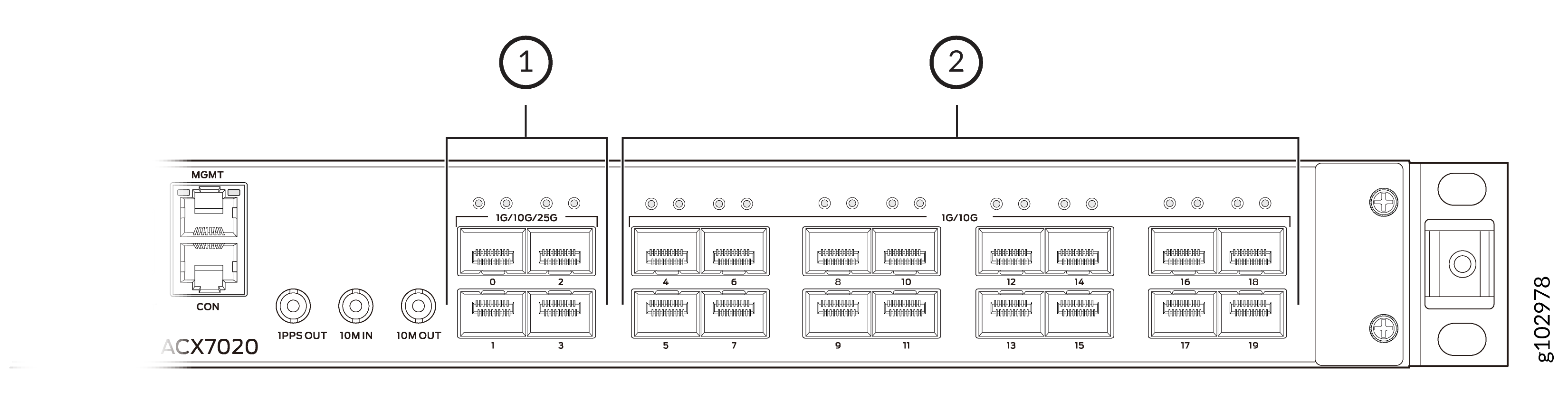
1 — Four 25GbE/10GbE/1GbE SFP28 ports | 2 — Sixteen 10GbE/1GbE SFP+ ports |
Management Panel on ACX7020 Routers
The management panel on ACX7020 routers is located on the front of the router.
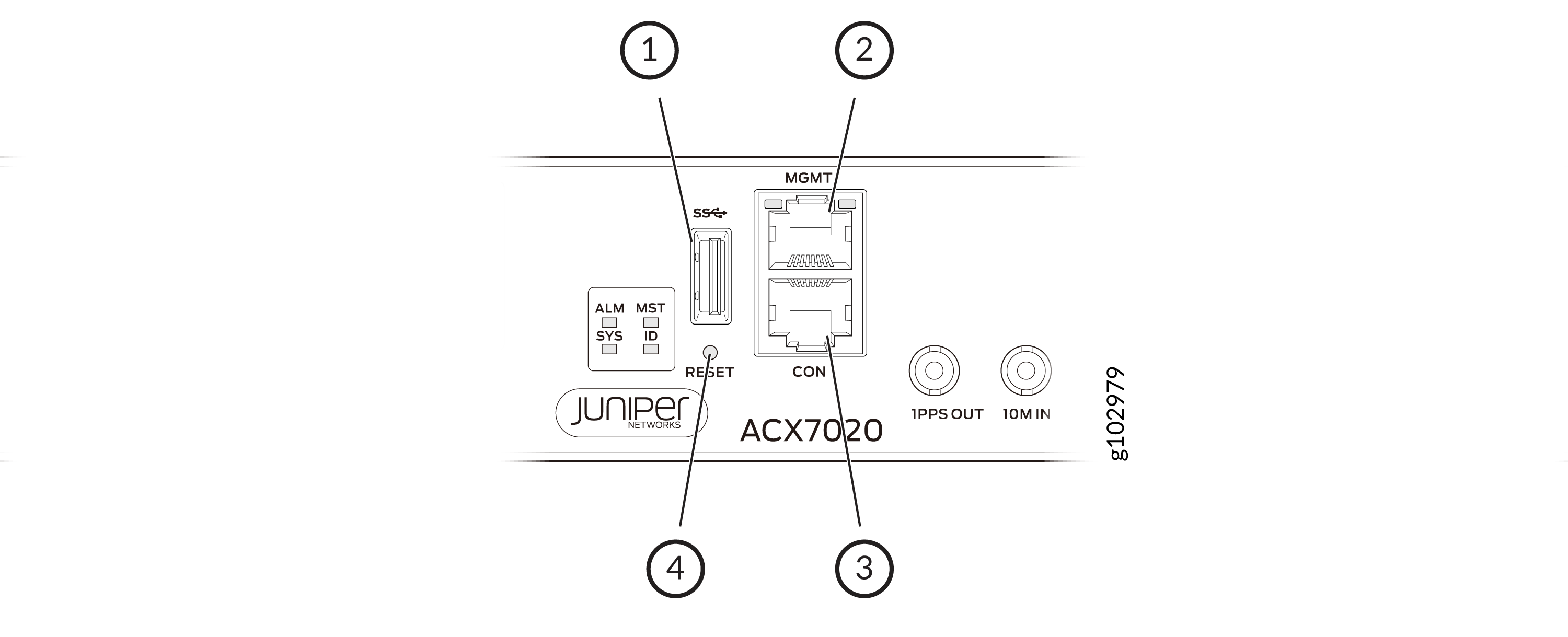
1 — USB 3.0 Type-A port | 3 — Console (CON) port |
2 — Management (MGMT) port | 4 — Reset (RESET) button |
The management panel on an ACX7020 router displays the router product number, and it consists of the following components:
-
USB Type-A port for image updates.
-
Management (MGMT) port—10/100/1000BASE-T port that uses an RJ-45 connector to connect to a management device for out-of-band management.
-
Console (CON) port—Uses an RJ-45 connector to connect to a console management device.
-
Reset (RESET) button to reset the router.
Timing Ports
The ACX7020 router is equipped with three timing ports.
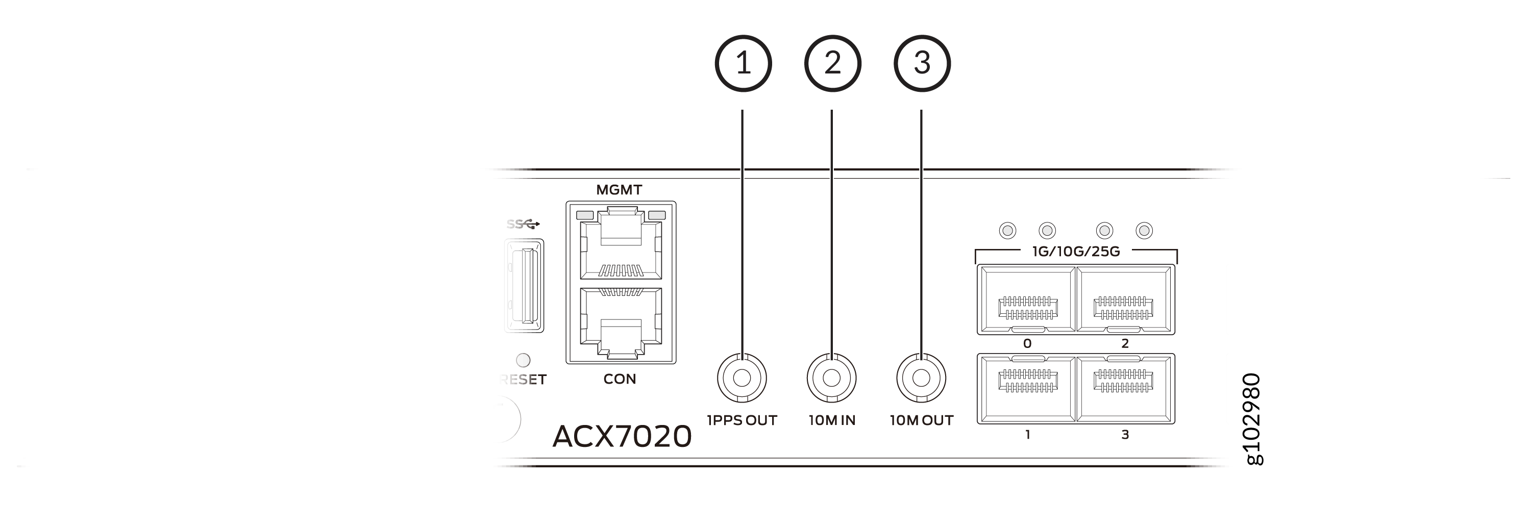
1 — 1PPS OUT port | 3 — 10M OUT port |
2 — 10M IN port |
Here's the definition of the ports and labels on the timing ports.
-
10M IN—10-MHz input clocking port for connecting to external clock signal sources. The clocking port synchronizes clock inputs based on the clock’s priority.
-
10M OUT—10-MHz output clocking port to provide a reference clock signal.
-
1PPS OUT—1-pulse per second (PPS) output port for time synchronization.
Management Port LEDs on ACX7020 Routers
The ACX7020 routers have a management port that has separate LEDs to indicate link status and link activity.
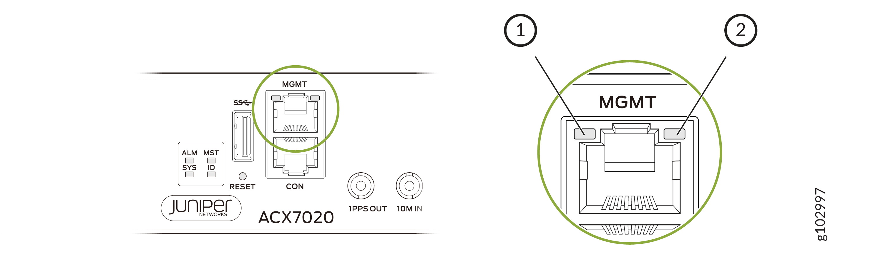
1 — Link activity LED | 2 — Status LED |
|
LED |
Color |
State |
Description |
|---|---|---|---|
|
Link activity LED |
Unlit |
Off |
No link is established. |
|
Green |
Blinking |
A link is established, and link activity is present. |
|
|
Status LED |
Unlit |
Off |
No link is established, or the port speed is 10 Mbps. |
|
Amber |
On steadily |
The port speed is 100 Mbps. |
|
|
Green |
On steadily |
The port speed is 1 Gbps. |
Chassis Status LEDs on ACX7020 Routers
Each ACX7020 router has four status LEDs that indicate the system status. You can find these LEDs to the left of the USB port
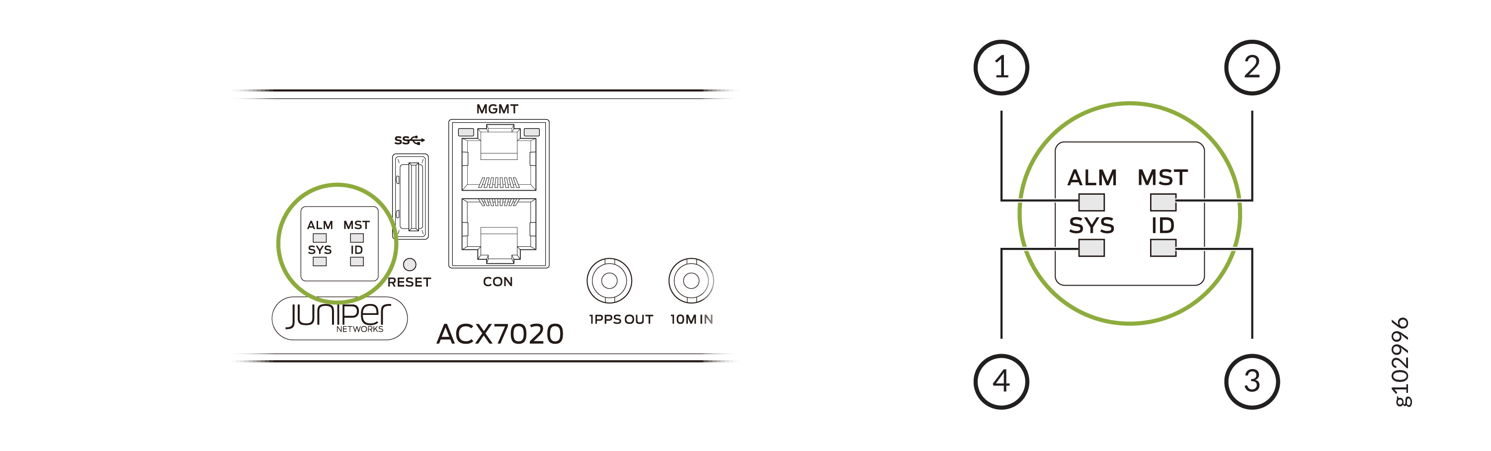
1 — ALM (Alarm) | 3 — ID (Identification) |
2 — MST (Primary) | 4 — SYS (System) |
Table 2 describes the chassis status
LEDs on ACX7020 routers, including their colors, states, and the corresponding
status they represent. You can view the colors of the LEDs remotely through the CLI
by running the operational mode command show chassis led.
|
Name |
Color |
State |
Description |
|---|---|---|---|
|
ALM—Alarm LED |
Unlit |
Off |
The router is halted, or there is no alarm. |
|
Red |
On steadily |
Indicates the presence of a critical situation, which could be related to either hardware or software. Begin by checking for hardware-related causes such as temperature anomalies or a power failure. Switch off power to the router and unplug the power cords. Correct any voltage or site temperature issues, and allow the router to cool down. Power on the router, and monitor the system LEDs to determine where the error is occurring. If the issue persists or is software-related, review the alarm details and take appropriate action based on the findings. |
|
|
Yellow |
On steadily |
Indicates the presence of a minor issue, which could be related to either hardware or software. If it is a hardware issue, try rebooting the router, as this may resolve the issue. If the issue persists or is software-related, review the alarm details and take appropriate action based on the findings. |
|
|
Red and Yellow |
Blinking |
Indicates the presence of a major and a minor alarm. |
|
|
SYS—System LED |
Unlit |
Off |
The router is powered off or halted. |
|
Green |
On steadily |
Junos OS Evolved is loaded on the router, and the router is online. |
|
|
Green |
Blinking |
The router is loading the software. |
|
|
Green |
Blipping (slow blink) |
The router is powering up. |
|
|
MST—Primary LED |
Green |
On steadily |
The router is a standalone router. |
|
Unlit |
Off |
The router is a linecard member. |
|
|
ID—Identification LED |
Unlit |
Off |
The beacon feature is not enabled on the router. You can enable
this feature by using the |
|
Blue |
Blinking |
The beacon feature is enabled on the router. You can disable this
feature by using the |
Network Port LEDs on ACX7020 Routers
Each ACX7020 network port has a single LED to indicate link status, activity on the link, or a fault condition.

1 — Upper-port LED | 2 — Lower-port LED |
Table 3 describes the network port LEDs on the ACX7020 routers, their colors and states, and the status that they indicate.
|
LED Color |
LED State |
Description |
|---|---|---|
|
Unlit |
Off |
There is no power, the link is down, or a transceiver is not present. |
|
Green |
On steadily |
A link is established, and all channels are up. |
|
Blinking |
The beacon function is enabled on the port. |
|
|
Amber |
On steadily |
The port is disabled in the CLI. |
|
Red |
On steadily |
All channels are down. |