Fast Track to Rack Installation and Power
This procedure guides you through the steps to install the ACX5400 router in a rack and connect it to power.
Install the ACX5400 Router in the Rack
You can install a Juniper Networks® ACX5400 router into a 19-inch four-post rack or a cabinet. We’ll walk you through the steps to install an AC-powered ACX5400 router in a 19-inch four-post rack.
Before you install, review the following:
To install the router in a four-post rack or cabinet:
-
Align the holes in the front-mounting rails with the holes on the side of
the chassis (see Figure 1 for
ACX5448, Figure 2 for
ACX5448-D, and Figure 3 for
ACX5448-M).
Figure 1: Install the Mounting Rails on an ACX5448 Router
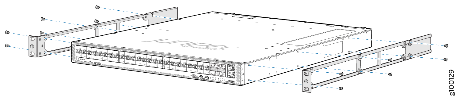 Figure 2: Install the Mounting Rails on an ACX5448-D Router
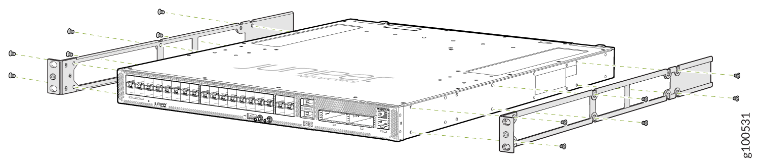 Figure 3: Install the Mounting Rails on an ACX5448-M Router
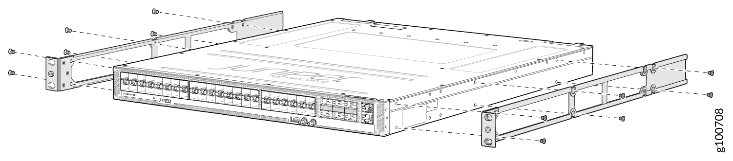
-
Carefully slide the chassis with the rails attached on to the rack rails
(see Figure 4 for the
ACX5448 router, Figure 5 for the
ACX5448-D router, and Figure 6 for the
ACX5448-M router).
Figure 4: Install the ACX5448 Router in a Four-Post Rack
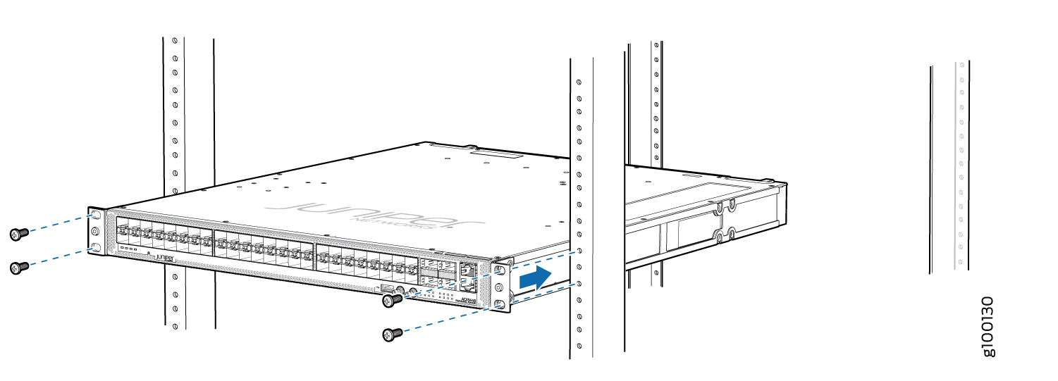 Figure 5: Install the ACX5448-D Router in a Four-Post Rack
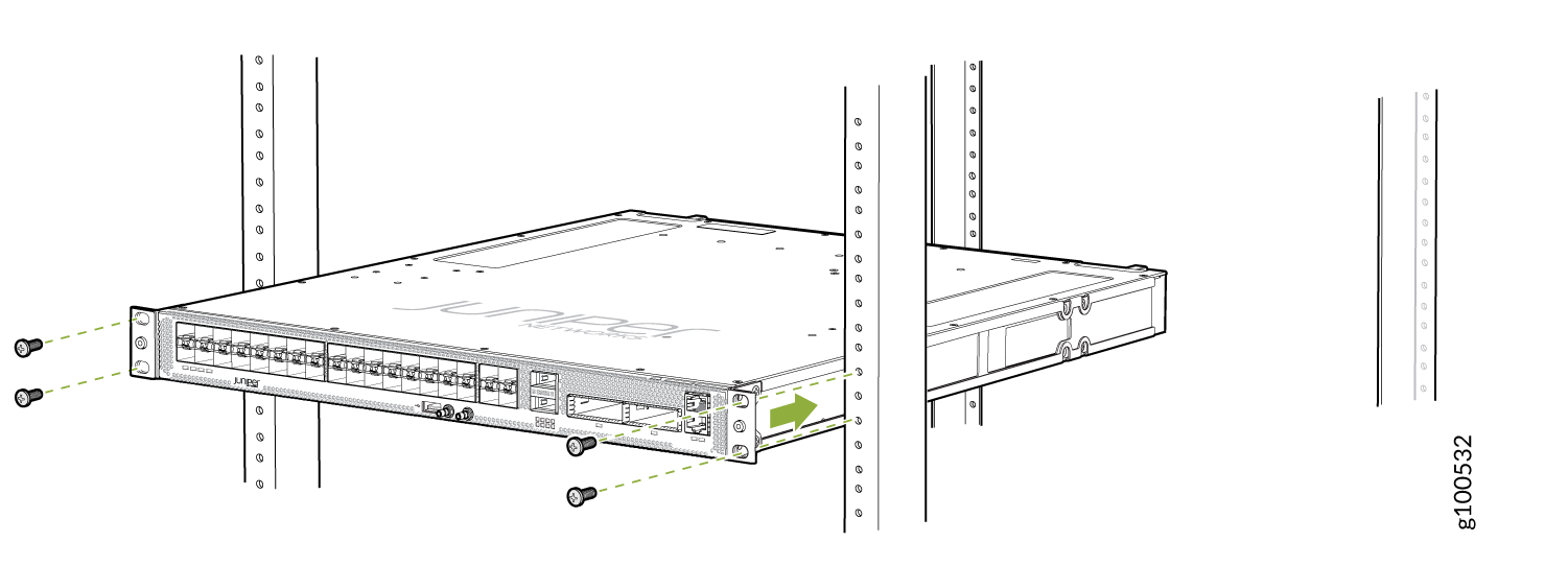 Figure 6: Install the ACX5448-M Router in a Four-Post Rack
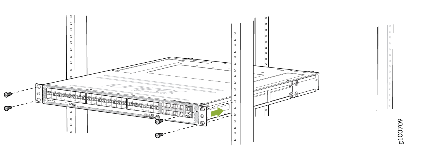
-
Install mounting screws into each of the front-mounting bracket holes
aligned with the rack, starting from the bottom, and secure them tightly.
Figure 7,
Figure 8, and Figure 9 show
the router fully secured to the front rails of the four-post rack.
Figure 7: ACX5448 Router Secured by Front-Mounting Brackets
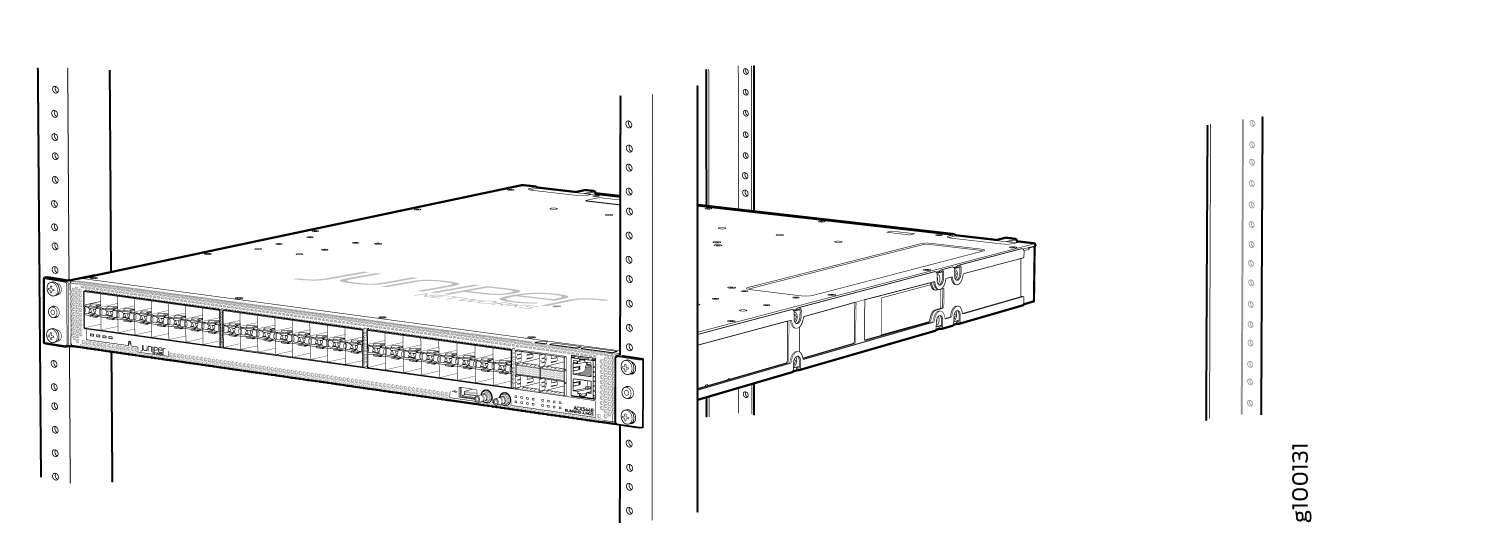 Figure 8: ACX5448-D Router Secured by Front-Mounting Brackets
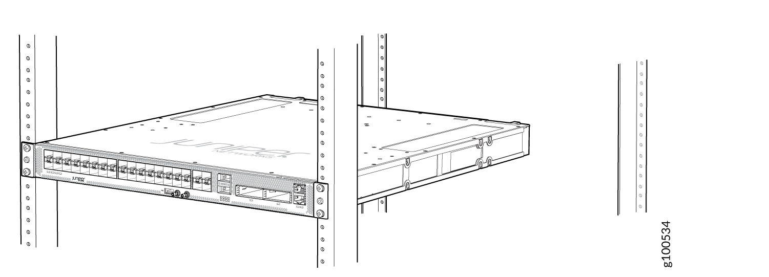 Figure 9: ACX5448-M Router Secured by Front-Mounting Brackets
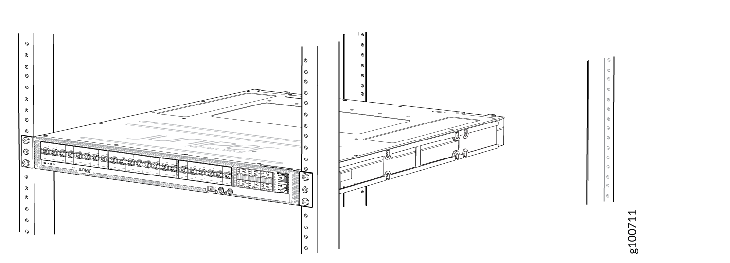
-
On the rear of the chassis, slide the rear-mounting blades on either side
of the chassis until the rear-mounting brackets at the end of the blades
contact the rack rails (see Figure 10 for the ACX5448
router, Figure 11
for the ACX5448-D router, and Figure 12 for the
ACX5448-M router).
The rear-mounting blades on each side of the chassis are movable. You can adjust the length of the blades according to the depth of the rack.
Figure 10: Install the Rear-Mounting Blades on an ACX5448 Router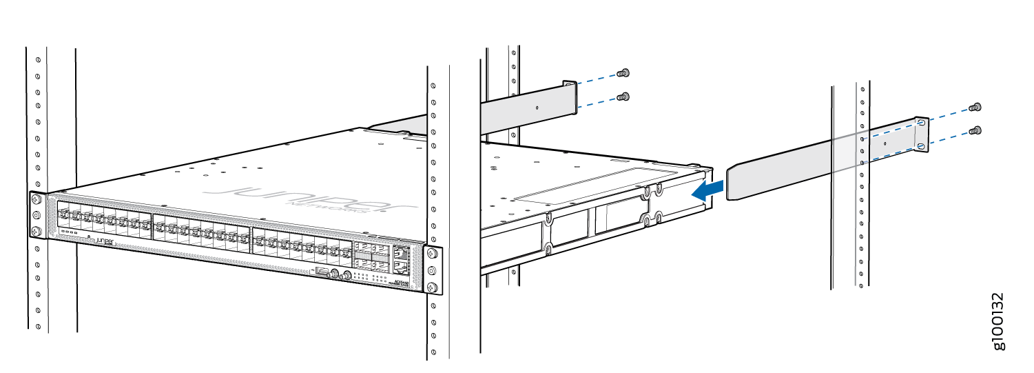 Figure 11: Install the Mounting Blades on an ACX5448-D Router
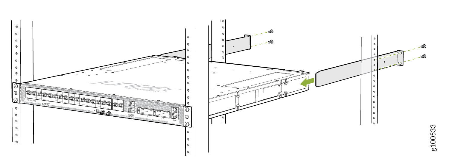 Figure 12: Install the Rear-Mounting Blades on an ACX5448-M Router
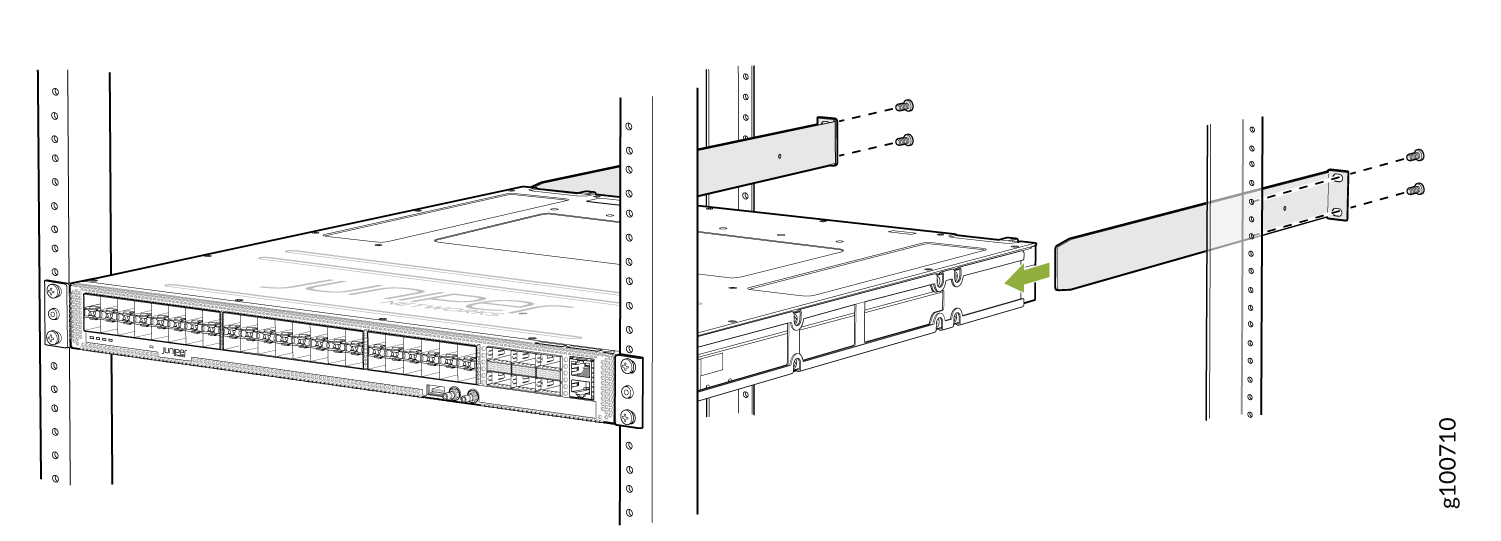
-
Visually inspect the alignment of the chassis. If you’ve installed the
chassis properly in the rack, all the mounting screws on one side of the
rack are aligned with the mounting screws on the opposite side, and the
router is level. Figure 13, Figure 14, and Figure 15 show the
router fully secured and installed in a four-post rack.
Figure 13: ACX5448 Router Installed in the Rack
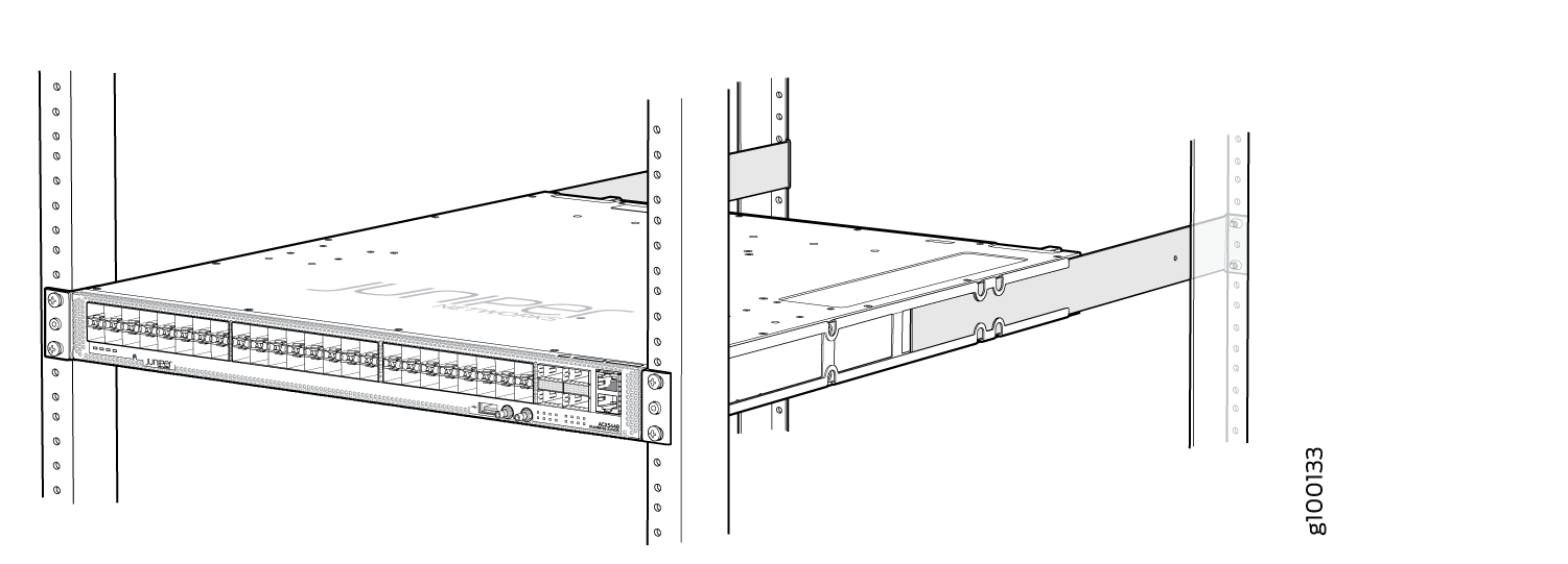 Figure 14: ACX5448-D Router Installed in the Rack
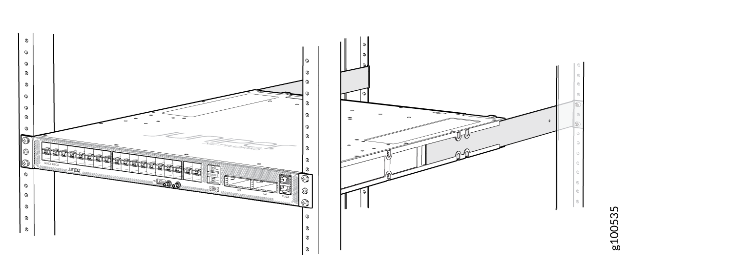 Figure 15: ACX5448-M Router Installed in the Rack
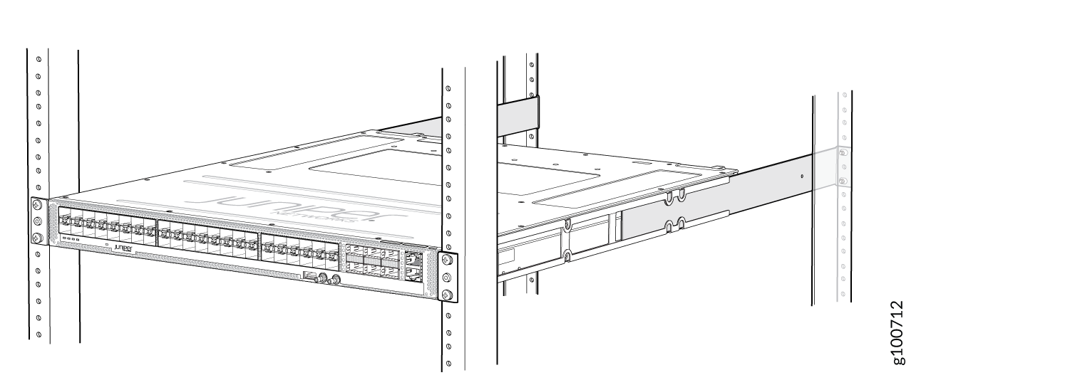
Connect to Power
To connect the ACX5400 router to AC power, perform the following steps:
Connect Earth Ground to ACX5400 Chassis
Before you connect earth ground to the protective earthing terminal of a ACX5400 router, ensure that a licensed electrician has attached an appropriate grounding lug to the grounding cable.
Figure 16, Figure 17, and Figure 18 show the grounding points on ACX5400 routers.
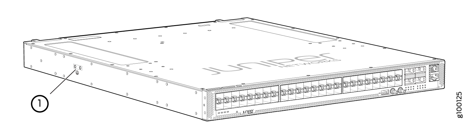
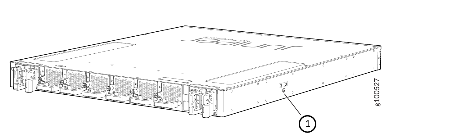

1 — Grounding points |
You need a protective earthing terminal bracket for connecting the chassis to earth ground. This two-holed bracket attaches on the side of the chassis through the mounting rail and provides a protective earthing terminal for the router. The grounding points are in the form of studs sized for #10–32 pan head screws. (You need to provide these screws with integrated washers as we do not ship them in the accessory kit). The grounding points are spaced at 0.63-in. (16-mm) centers.
You ground the router by connecting one end of a grounding cable to earth ground and then attaching the other end to the chassis grounding points by using two #10–32 pan head screws. You must provide the grounding cables.
The grounding lug required is a Panduit LCD10-10A-L or equivalent (not provided). The grounding lug accommodates 12 AWG (2.5 mm²) stranded wire. The grounding cable that you provide for the chassis must be the same size or heavier than the input wire of each power supply. Minimum recommendations are 12 AWG (2.5 mm²) stranded wire, 60° C wire for the ACX5448 router and 12 AWG (2.5 mm²), 90° C temperature-rated stranded wire for the ACX5448-D and ACX5448-M routers.
To ground the ACX5400 router:
-
Place the grounding cable lug over the grounding points on the side of
the chassis (see Figure 19 for ACX5448 and ACX5448-D routers and Figure 20 for the ACX5448-M router).
Figure 19: Connect the Grounding Cable to the ACX5448 or ACX5548-D Router
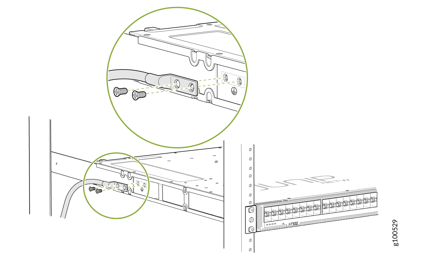 Figure 20: Connect the Grounding Cable to the ACX5448-M Router
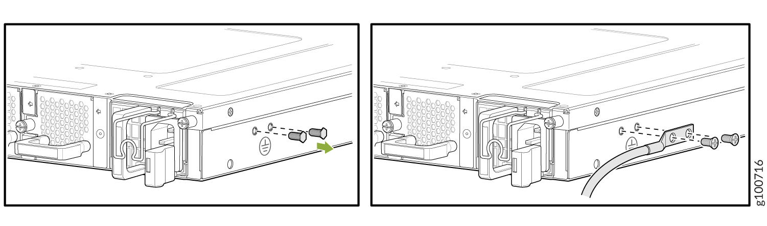
Connect AC Power to an ACX5400 Router
Ensure that you have a power cord appropriate for your geographical location available to connect AC power to the router.
Before you begin connecting AC power to the router:
-
Ensure that you have taken the necessary precautions to prevent electrostatic discharge (ESD) damage (see Prevention of Electrostatic Discharge Damage).
-
Ensure that you have connected the router chassis to earth ground.
CAUTION:Before you connect power to the router, a licensed electrician must attach a cable lug to the grounding and power cables that you supply. A cable with an incorrectly attached lug can damage the router (for example, by causing a short circuit).
To meet safety and electromagnetic interference (EMI) requirements and to ensure proper operation, you must connect the chassis to earth ground before you connect it to power. Under all circumstances, use the protective earthing terminal on the router chassis to connect to the earth ground. The router gains additional grounding when you plug the PSM in the router to a grounded AC power outlet by using the AC power cord appropriate for your geographical location.
-
Install the PSM in the chassis.
The power supply module (PSM) in an ACX5400 router is a hot-removable and hot-insertable field-replaceable unit (FRU). You can remove and replace it without powering off the router or disrupting routing functions.
You must connect each PSM to a dedicated power source outlet.
To connect AC power to an ACX5448 router:
-
Push the end of the AC power cord retainer strip into the hole next to
the inlet on the power supply faceplate on the router until it snaps
into place. Ensure that the loop in the retainer strip faces toward the
power cord.
Figure 21 shows the port on the AC PSM for ACX5448 router where the power cord retainer is installed.
Figure 21: Power Cord Retainer Port on the AC PSM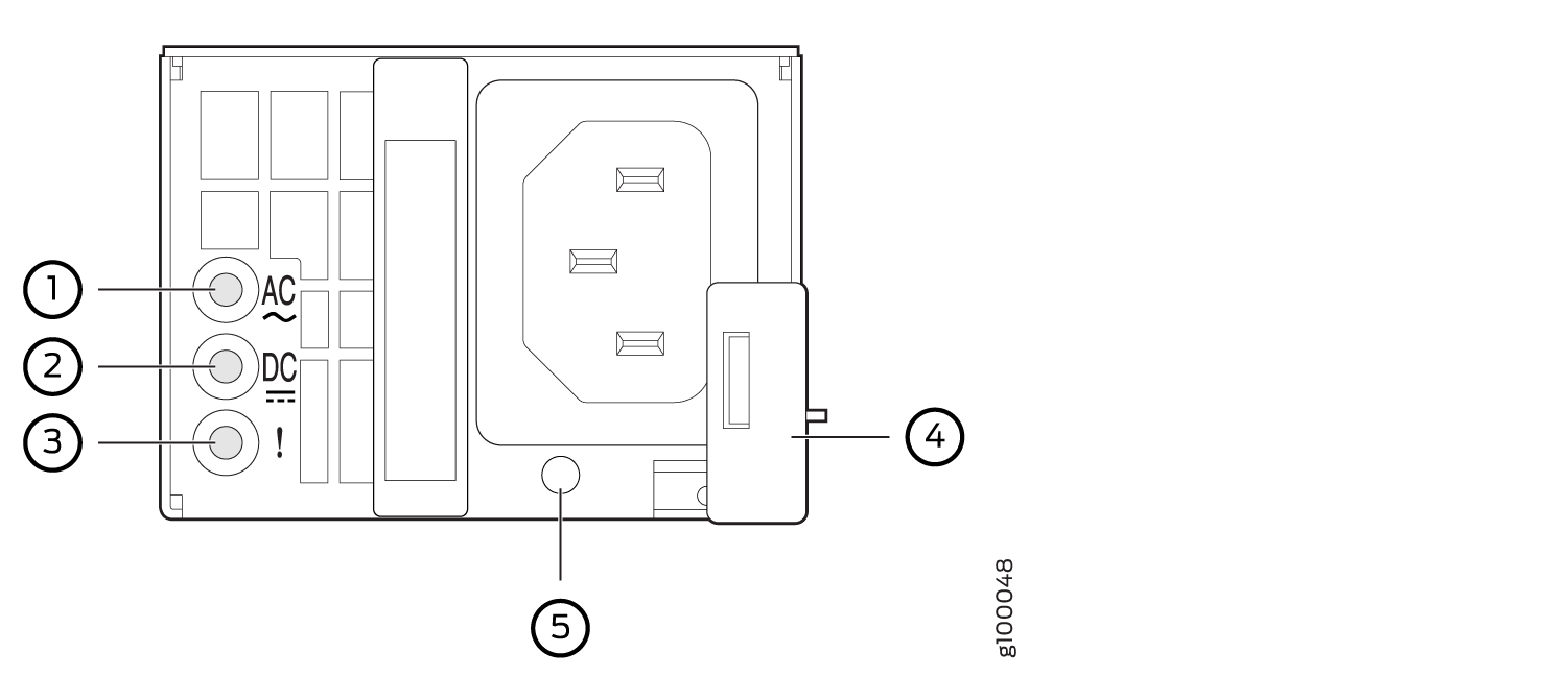 1—
1—Input status LED
4—Ejector lever
2—Output status LED
5—AC power cord retainer port
3—Fault LED
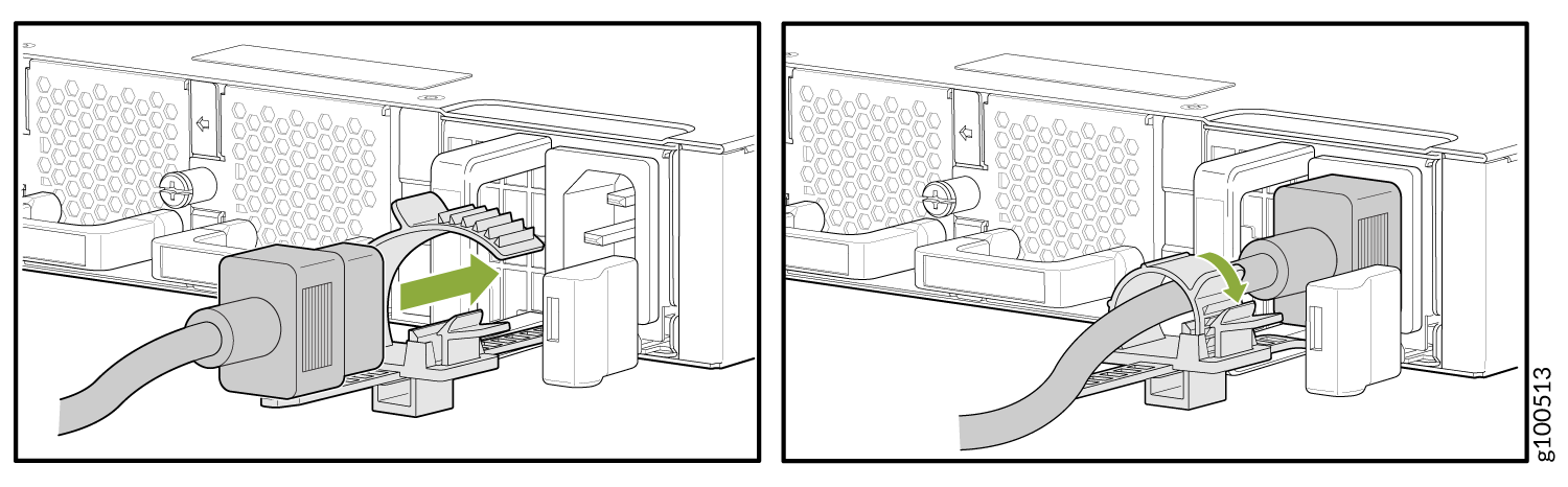
Figure 22 shows the power cord retainer installed on the AC PSM for ACX5448 router.
Figure 22: Power Cord Retainer Installed on the AC PSM for ACX5448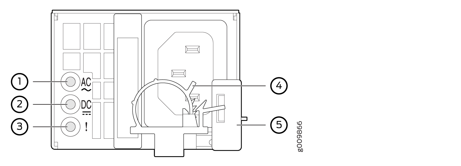 1—
1—Input status LED
4—AC power cord retainer installed
2—Output status LED
5—Ejector lever
3—Fault LED
To connect AC power to ACX5448-D and ACX5448-M routers:
Wrap and fasten one end of the ESD grounding strap around your bare wrist, and connect the other end of the strap to the ESD point on the chassis.
Power off the AC input appliance inlet on the source power supply.
Connect the power cord to the source power supply.
Note:Each PSM must be connected to a dedicated AC power feed and a dedicated customer-site 2-pole circuit breaker. We recommend that you use a dedicated customer-site circuit breaker rated for 20 A (110 VAC) or 16 A (220 VAC) minimum, or as required by local code.
Push the power cord retainer onto the power cord.
Figure 24 shows the power cord retainer installed on the AC PSM for the ACX5448-D and ACX5448-M router and Figure 25 shows how to connect an AC power cord to an ACX5448-D or ACX5448-M router.
Figure 24: Power Cord Retainer Installed on the AC PSM for ACX5448-D and ACX5448-M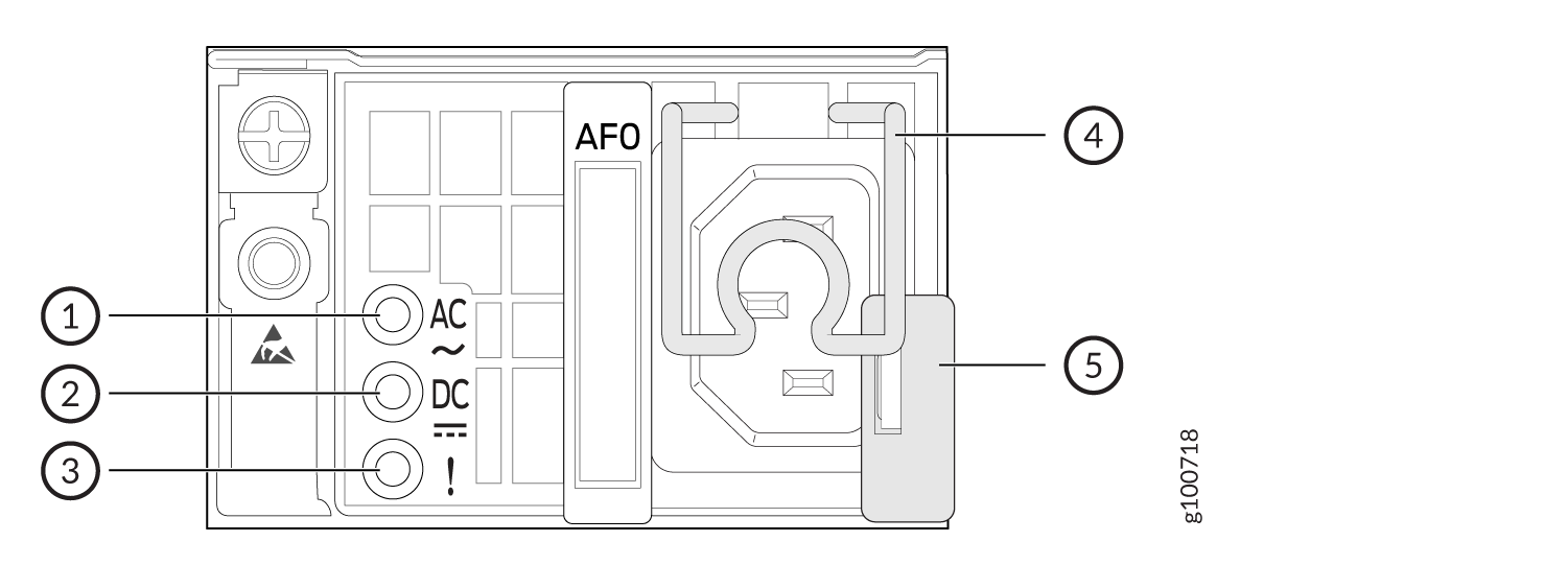 1—
1—Input status LED
4—AC power cord retainer installed
2—Output status LED
5—Ejector lever
3—Fault LED
Figure 25: : Connect an AC Power Cord to an ACX5448-D or ACX5448-M router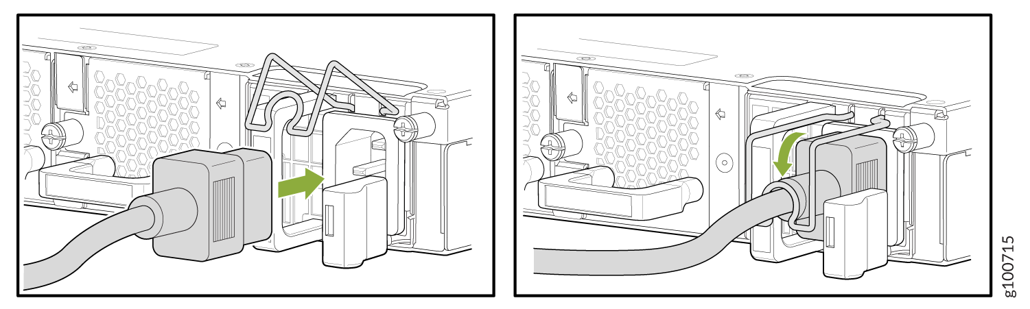
Power on the power supply at source.