ACX5448, ACX5448-D, and ACX5448-M Chassis
The front panel on the ACX5400 chassis contains LEDs for the router components, a reset button, management and console ports, and network ports. On the front panel, you can view status and troubleshooting information at a glance.
The rear panel of the router has slots for the power supply modules (PSMs) and fan modules. The power and fan modules are installed from the rear of the router.
Management Panel of ACX5400 Routers
The management panel of ACX5400 routers is found on the front of the router.
Figure 1 shows the management panel components on an ACX5448 router.
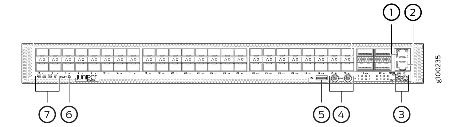
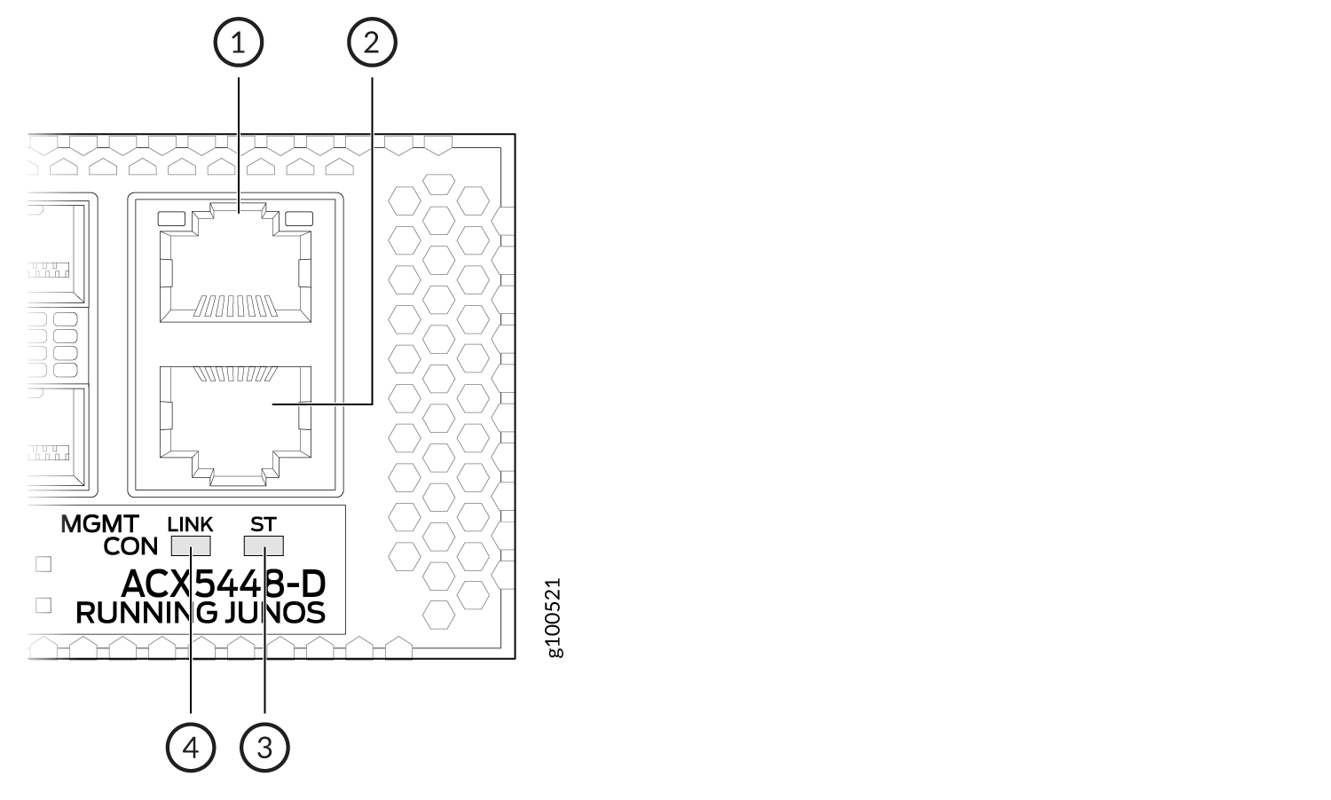
Figure 2 shows the management panel components on an ACX5448-D router.
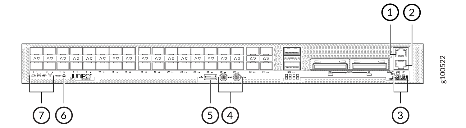
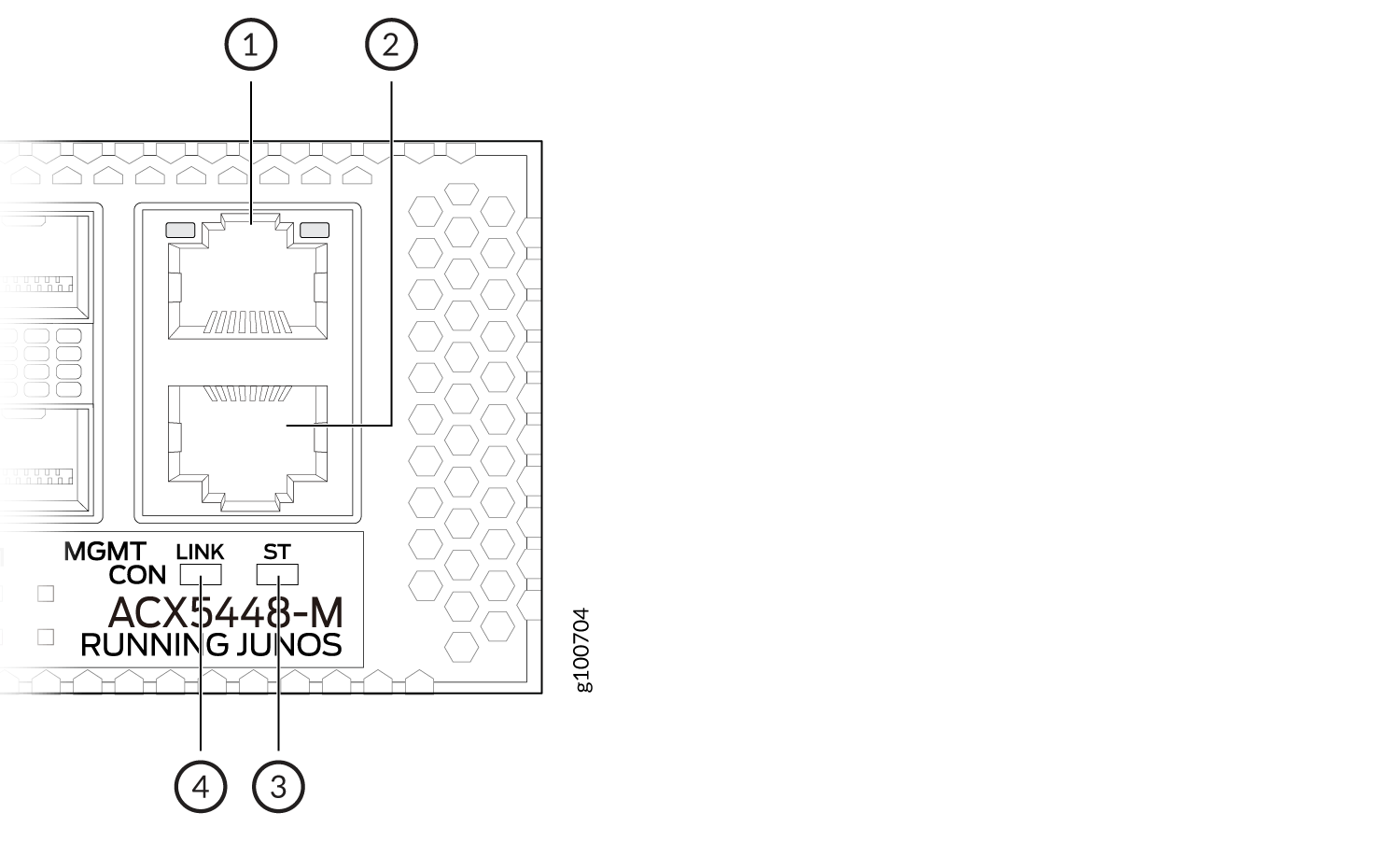
Figure 3 shows the management panel components on ACX5448-M routers.
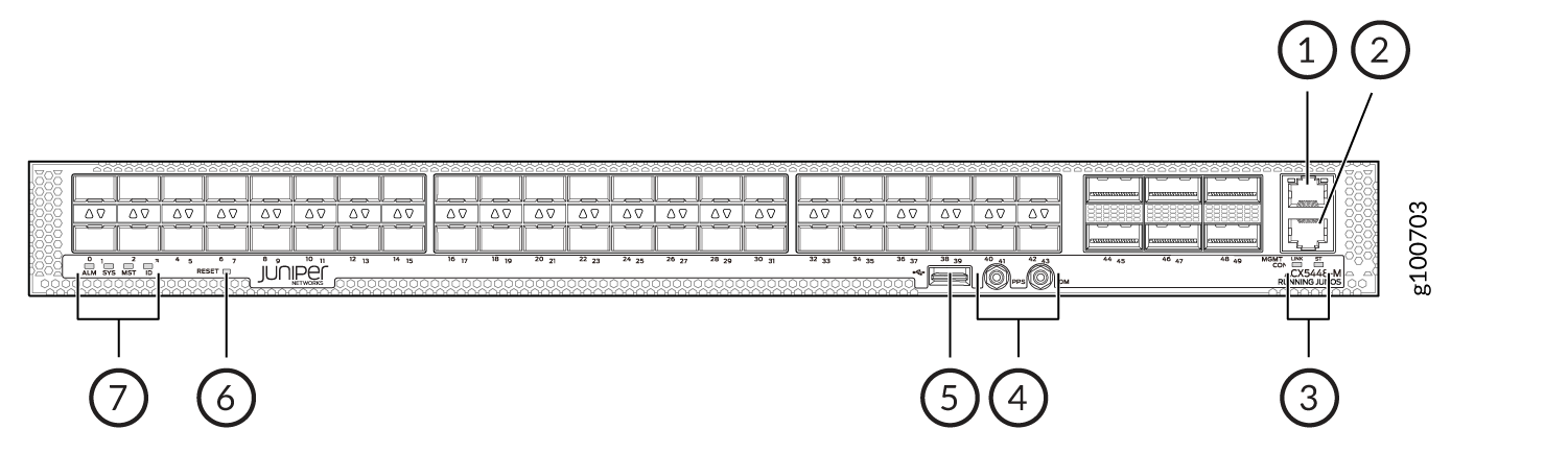
1 — Management (MGMT) port | 5 — USB port |
2 — Console (CON) port | 6 — RESET button |
3 — LINK and ST LEDs | 7 — Status LEDs |
4 — PPS and 10M GPS output ports |
The management panel consists of the following components:
-
Status LEDs—ALM, SYS, MST, and ID LEDs
-
Router product number
-
Management (MGMT) port— RJ-45 connectors for 10/100/1000BASE-T. See Connect an ACX5400 Router to a Network for Out-of-Band Management.
-
Console (CON) port— RJ-45 connector to support RS-232 serial ports.
-
Link activity (left LED labeled LINK) and port status (right LED labeled ST) LEDs.
-
USB port for image updates.
-
Reset button to reset the device.
-
Two SMB connector ports that support 1-PPS and 10-MHz timing devices.
Port Panel of ACX5400 Routers
Port Panel of an ACX5448 Router
The port panel of the ACX5448 router has the following port configurations:
-
Forty-eight 10-Gigabit or 1-Gigabit Ethernet ports (ports 0 through 47) that operate at 10-Gbps speed with SFP+ transceivers or at 1-Gbps speed when you use SFP optics.
-
Four 100-Gigabit Ethernet ports (ports 48 through 51) that support quad small form-factor pluggable 28 (QSFP28) transceivers. You can channelize these ports into four 25-Gbps interfaces using breakout cables (and channelization configuration). These ports also support 40-Gbps speed, when you use QSFP+ optics. You can channelize these 40-Gbps ports into four 10-Gbps interfaces using breakout cables (and channelization configuration).
Figure 4 shows the port panel of an ACX5448 router.
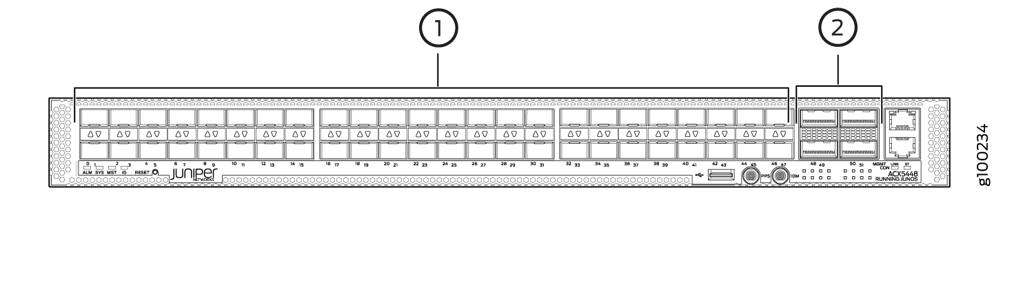
1 — 1-Gigabit/10–Gigabit Ethernet ports (48 SFP+ or SFP ports) | 2 — 100–Gigabit Ethernet ports (4 QSFP28 ports) |
Port Panel of an ACX5448-D Router
The port panel of the ACX5448-D router has the following port configurations:
-
Thirty-six 10-Gigabit or 1-Gigabit Ethernet ports (0 through 35, mapped to CLI PIC 0) that operate at 10-Gbps speed with SFP+ transceivers or at 1-Gbps speed when you use SFP optics.
-
Two 100-Gigabit Ethernet ports (36 and 37, mapped to CLI PIC 1) that support QSFP28 transceivers. You can channelize these ports into four 25-Gbps interfaces using breakout cables (and channelization configuration). These ports also support 40-Gbps speed, when you use QSFP+ optics. You can channelize these 40-Gbps ports into four 10-Gbps interfaces using breakout cables (and channelization configuration).
-
Two 200-Gigabit Ethernet ports (38 and 39, mapped to logical PIC 2) that support 200-gigabit CFP2-DCO transceivers.
One QSFP28 port (port 36) and one CFP2-DCO port (port 38) can operate as multiplexer ports.
Figure 5 shows the port panel of an ACX5448-D router.
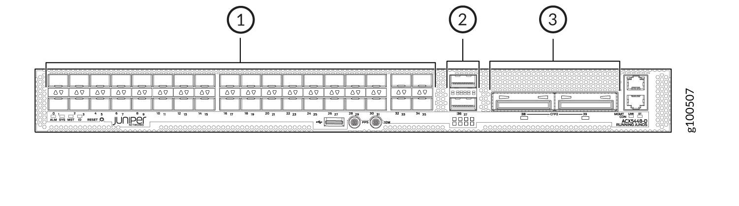
1 — 1- Gigabit/10–Gigabit Ethernet ports (36 SFP+ or SFP ports) | 3 — 100–Gigabit/200-Gigabit Ethernet ports (2 CFP2-DCO ports) |
2 — 100–Gigabit Ethernet ports (2 QSFP28 ports) |
- Port, Interface, and PIC Mapping
- Default Port Configuration on ACX5448-D
- Multiplexing on ACX5448-D Routers
- Enable Multiplexing by Changing the Default Configuration
- LED Behavior for CFP2 Ports
Port, Interface, and PIC Mapping
The ACX5448-D does not have a physical FPC or PIC. FPC 0 refers to the router. The ports on the front panel are mapped to logical PICs as follows:
-
Ports 0–35 mapped to PIC 0 (interfaces xe-0/0/0 through xe-/0/0/35)
-
Ports 36 and 37 mapped to PIC 1 (interfaces et-0/1/0 and et-0/1/1)
-
Ports 38 and 39 mapped to PIC 2 (interfaces ot-0/2/0 and ot-0/2/1)
For each CFP2-DCO optical module installed in ports 38 and 39, one optical transport (ot-) interface is created. Therefore, the ACX5448-D supports two ot- interfaces—ot-0/2/0 and ot-0/2/1. You can map two 100-Gigabit Ethernet (et-) interfaces to each ot- interface, depending on the configured rate—100 Gbps or 200 Gbps—for the CFP2-DCO module. As a result, four et- interfaces are possible—et-0/2/0, et-0/2/1, et-0/2/2, and et-0/2/3.
The optical interface to et mapping is displayed
in the following table:
|
|
Port Number |
Modulation Format |
Mapped |
|---|---|---|---|
|
ot-0/2/0 |
Port 38 |
QPSK-100G |
et-0/2/0 |
|
8QAM-200G |
et-0/2/0 et-0/2/1 |
||
|
16QAM-200G |
et-0/2/0 et-0/2/1 |
||
|
ot-0/2/1 |
Port 39 |
QPSK-100G |
et-0/2/2 |
|
8QAM-200G |
et-0/2/2 et-0/2/3 |
||
|
16QAM-200G |
et-0/2/2 et-0/2/3 |
Default Port Configuration on ACX5448-D
By default (factory-default configuration), when you power on an ACX5448-D router, the following port combinations are available:
-
36 SFP+ ports (ports 0 through 35)—These ports can operate as native 10-Gigabit Ethernet interfaces or as 1-Gigabit Ethernet interfaces when you use 1-gigabit optics.
-
Two QSFP28 ports (36 and 37)—The interface for port 36 is not created. However, you can configure port 37 as native 100-Gigabit or 40-Gigabit Ethernet interfaces, or channelize these ports into four 25-Gigabit Ethernet or 10-Gigabit Ethernet interfaces, respectively, by using CLI configuration and breakout cables.
-
Two CFP2 ports (38 and 39)—You can configure each of the CFP2 ports as a 200-Gigabit Ethernet port.
Multiplexing on ACX5448-D Routers
As we have seen in the preceding sections, the et-0/1/0 interface is created for QSFP28 port 36 and the ot-0/2/0 interface is created for CFP2 port 38. The ot-0/2/0 interface is mapped to the et- interfaces et-0/2/0 and et-0/2/1.
The QSFP28 port 36 (interface et-0/1/0) and the CFP2 port 38 (interface et-0/2/1) operate as multiplexer (also called mux) ports.
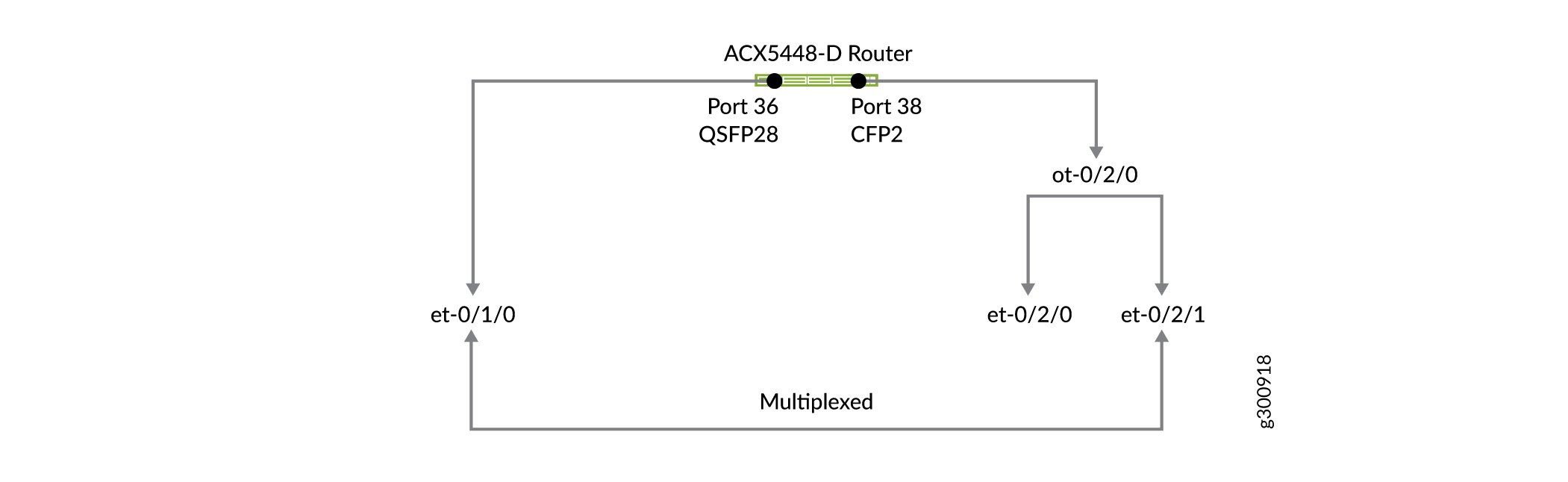
When you start up the router, the et-0/1/0 interface on port 36 is not created by default. However, the interface et-0/2/0
(on port 38) is always available. You can enable
the et-0/1/0 interface (on port 36) by running
the set chassis fpc 0 cfp-to-et command and restarting
the FPC by executing the restart chassis-control command.
(This configuration deletes the interface et-0/2/1 on port 38.)
Therefore, you can change the factory-default port combination for the QSFP28 and CFP2 ports to the following:
-
QSFP28 ports 36 and 37—Enable the et-0/1/0 interface on port 36. You can configure ports 36 and 37 as native 100-Gigabit or 40-Gigabit Ethernet interfaces, or channelize them into four 25-Gigabit Ethernet or 10-Gigabit Ethernet interfaces, respectively, by using CLI configuration and breakout cables.
-
CFP2 ports 38 and 39—Configure port 38 as a 100-Gigabit Ethernet port and port 39 as a 200-Gigabit Ethernet port.
Enable Multiplexing by Changing the Default Configuration
In the factory-default configuration, the interface for port 36 is not created. You need to enable it and then operate it as a multiplexed port 38 (interface et-0/2/1). To change the factory-default port combination and enable the et-0/1/0 interface (port 36):
-
Include the
set chassis fpc 0 cfp-to-etcommand at the[edit]hierarchy level in the configuration mode.[edit] user@host# set chassis fpc 0 cfp-to-et
-
Commit the configuration.
[edit]
user@host# commit
-
Restart the FPC.
user@host> restart chassis-control
This configuration deletes the et-0/2/1 interface (on port 38) and creates the et-0/1/0 interface (on port 36). After you change the factory-default port combination, the modified port combination will become the default port combination when you power on the device.
Before changing this default behavior, plan to handle disruption of services.
LED Behavior for CFP2 Ports
Table 1 summarizes the LED port behavior for CFP2 DCO ports.
|
Mode |
Color |
State |
Description |
First |
Second |
First |
Second |
|
200G |
Green |
On |
Indicates that the port is up and the port speed is 200 Gbps but there is no traffic passing. |
Up |
Up |
Off |
Off |
|
200G |
Green |
Flashing |
Indicates that the port speed is 200 Gbps, and there is some activity. |
Up |
Up |
On |
On |
|
100G |
Amber |
On |
Indicates that the port is up and the port speed is 100 Gbps but there is no traffic passing. |
Up |
Down |
Off |
Off |
|
Down |
Up |
Off |
Off |
||||
|
100G |
Amber |
Flashing |
Indicates that the port is up and the port speed is 100 Gbps and there is some activity. |
Up |
Down |
On |
Off |
|
Down |
Up |
Off |
On |
||||
|
Up |
Up |
On |
Off |
||||
|
Up |
Up |
Off |
On |
||||
|
Unlit |
Off |
There is no link on the port. |
The first et- interface in Table 1 refers to the et-0/2/0 interface (port 38) or the et-0/2/2 interface (port 39).
Similarly, the second et interface refers to the et-0/2/1 interface (port 38) or the et-0/2/3 interface (port 39).
Port Panel of an ACX5448-M Router
The port panel of the ACX5448-M router has the following port configurations:
-
Forty-four 10-Gigabit or 1-Gigabit Ethernet ports (0 through 43) that support small form-factor pluggable plus (SFP+) transceivers. These ports can also operate at 1-Gbps speed when you use 1-gigabit SFP optics.
-
Six 100-Gigabit Ethernet ports (44 through 49) that support quad small form-factor pluggable 28 (QSFP28) transceivers. You can channelize these ports into four 25-Gbps interfaces using breakout cables (and channelization configuration). These ports also support 40-Gbps speed, when you use QSFP+ optics. You can channelize these 40-Gbps ports into four 10-Gbps interfaces using breakout cables (and channelization configuration).
Note:The ACX5448-M routers support advanced security capabilities such as Media Access Control Security (MACsec). MACsec is supported only on the forty-four 10-Gigabit or 1-Gigabit Ethernet ports.
Figure 6 shows the port panel of an ACX5448-M router.
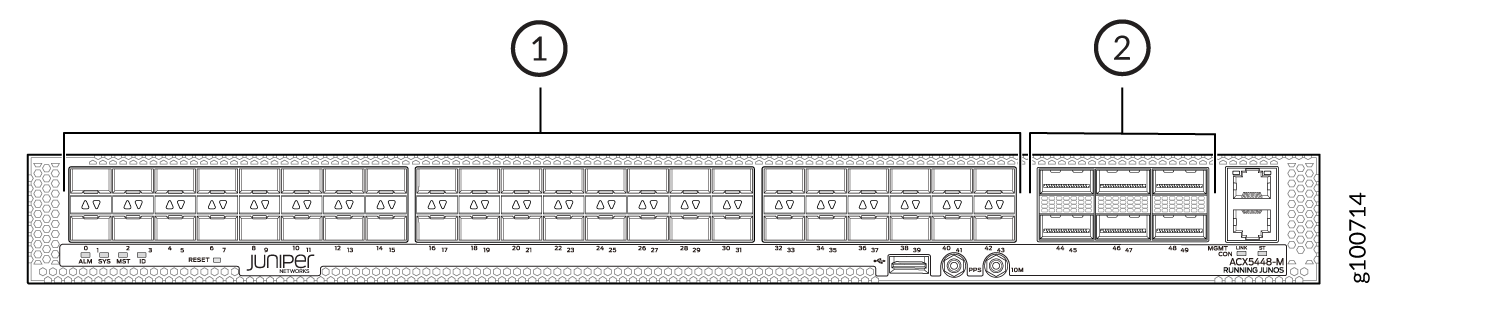
1 — 1-Gigabit/10–Gigabit Ethernet ports (44 SFP+ or SFP ports) | 2 — 100–Gigabit Ethernet ports (6 QSFP28 ports) |
Chassis Status LEDs on ACX5400 Routers
The ACX5400 routers have four status LEDs on the front side of the chassis (see callout 7 in Figure 7).
1 — Management (MGMT) port | 5 — USB port |
2 — Console (CON) port | 6 — RESET button |
3 — LINK and ST LEDs | 7 — Status LEDs |
4 — PPS and 10M GPS output ports |
Table 2 describes
the chassis status LEDs on ACX5400 routers, their colors and states,
and the status they indicate. You can view the colors of the three
LEDs remotely through the CLI by issuing the operational mode command show chassis lcd.
|
Name |
Color |
State |
Description |
|---|---|---|---|
|
ALM–Alarm or beacon |
Unlit |
Off |
The router is halted or there is no alarm. |
|
Red |
On steadily |
A major hardware fault has occurred, such as a temperature alarm or power failure, and the router has halted. Power off the router by setting the AC power source outlet to the off (O) position and unplugging the AC power cords. Correct any voltage or site temperature issues, and allow the router to cool down. Power on the router and monitor the power supply and fan LEDs to help determine where the error is occurring. |
|
|
Amber |
On steadily |
A minor alarm has occurred, such as a software error. Power off the router by setting the AC power source outlet to the off (O) position and unplugging the AC power cords. Power on the router and monitor the status LEDs to ensure that Junos OS boots properly. |
|
|
SYS–System |
Unlit |
Off |
The router is powered off or halted. |
|
Green |
On steadily |
Junos OS for ACX Series is loaded on the router. |
|
|
MST–Primary |
Unlit |
Off |
The router is a linecard member. |
|
Green |
On steadily |
The router is a standalone router. |
|
|
ID–Identification |
Unlit |
Off |
The beacon feature is not enabled on the router. This
feature is enabled using the |
|
Blue |
Blinking |
The beacon feature is enabled on the router. This feature
is enabled using the |
Management Port LEDs on ACX5400 Routers
The management ports (labeled MGMT) for 10/100/1000BASE-T connections on ACX5400 routers have two LEDs that indicate link status and link activity (see callout 3 and 4 in Figure 10). The right LED indicates status; the left LED indicates link activity.
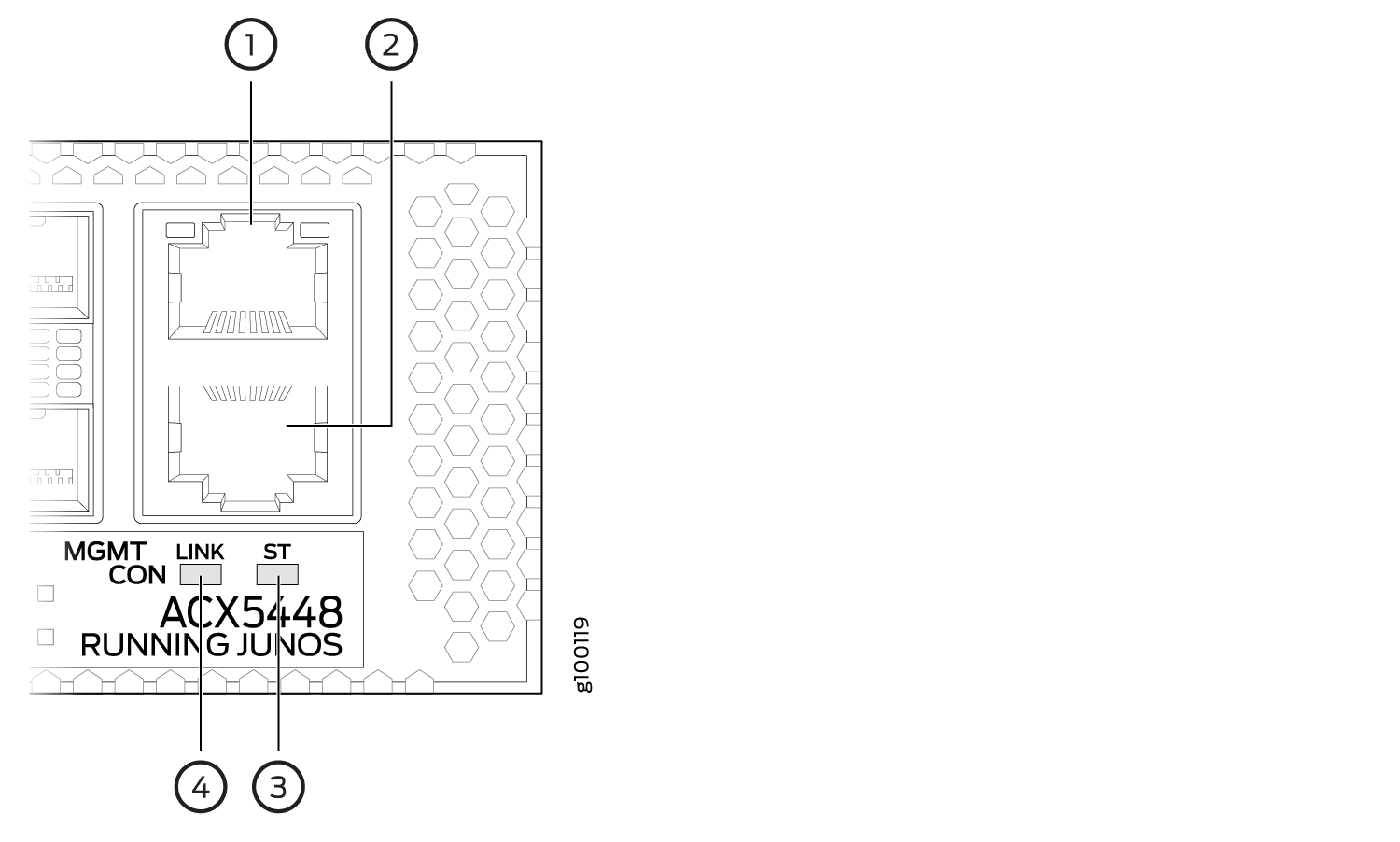
1 — Management (MGMT) port | 3 — Status (ST) LED |
2 — Console (CON) port | 4 — Link activity (LINK) LED |
Table 3 describes the management port LEDs.
|
LED |
Color |
State |
Description |
|---|---|---|---|
|
LINK (Link Activity; left) |
Green |
Blinking or flickering |
A link is established, and there is link activity. |
|
On steadily |
A link is established, but there is no link activity. |
||
|
Off |
No link is established, there is a fault, or the link is down. |
||
|
ST (Status; right) |
Green |
Blinking at an interval of 200 ms |
Indicates that the port speed is 10 Mbps. |
|
Blinking at an interval of 83 ms |
Indicates that the port speed is 100 Mbps. |
||
|
On steadily |
Indicates that the port speed is 1000 Mbps. |
Network Port LEDs on ACX5400 Routers
The ACX5400 routers use bicolored LEDs to indicate link activity on and status of network ports. The link LED indicates link activity or a fault. The status LED indicates transceiver presence.
Table 4 describes how to interpret the SFP+ port LEDs.
Mode |
Color |
State |
Description |
|---|---|---|---|
1-Gigabit Ethernet or 10-Gigabit Ethernet |
Green |
On or flashing |
Indicates that the port speed is 10 Gbps, and there is some activity. |
Amber |
On or flashing |
Indicates that the port speed is 1 Gbps, and there is some activity. |
|
Off |
Unlit |
There is no link on the port. |
Table 5 describes how to interpret the QSFP28 LEDs.
Mode |
Color |
State |
Description |
|---|---|---|---|
100-Gigabit Ethernet |
Green |
On or flashing |
Indicates that the port speed is 100 Gbps, and there is some activity. |
Off |
Unlit |
There is no link on the port. |
|
40-Gigabit Ethernet |
Amber |
On or flashing |
Indicates that the port speed is 40 Gbps, and there is some activity. |
Off |
Unlit |
There is no link on the port. |
|
25-Gigabit Ethernet |
Green |
On or flashing |
Indicates that the port speed is 25 Gbps (using a breakout cable), and there is some activity. |
Off |
Unlit |
There is no link on the port. |
|
10-Gigabit Ethernet |
Amber |
On or flashing |
Indicates that the port speed is 10 Gbps (using a breakout cable), and there is some activity. |
Off |
Unlit |
There is no link on the port. |
There are four bicolor lane LEDs for each QSFP28 port that are located just below the QSFP28 ports. The first LED is used and the remaining LEDs are not used when the port is configured as a 40-Gigabit Ethernet or 100-Gigabit Ethernet interface, and connected to a QSFP28 transceiver. All four LEDs are used when the port is configured as a 10-Gigabit Ethernet or 25-Gigabit Ethernet interface, and the port is connected using an optical split cable (breakout cable) or a direct attach copper breakout (DACBO) cable.
Fan Status LEDs on ACX5400 Routers
The fan modules on ACX5400 routers do not have any LEDs—the fan status LEDs are located next to the fan module slots on the ACX5400 chassis. Figure 13 shows the location of the LED next to the fan module.
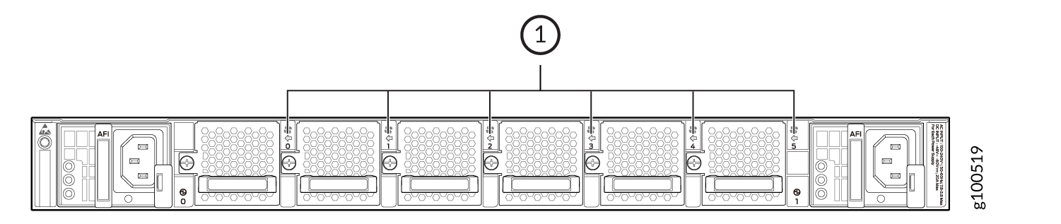
1 — Fan LEDs |
Table 6 describes the function of the fan status LED.
|
Name |
Color |
State |
Description |
|---|---|---|---|
|
Fan |
Green |
On steadily |
The fan module is operating normally. The system has verified that the module is engaged, that the airflow is in the correct direction, and that the fan is operating correctly. |
|
Red |
On steadily |
An error has been detected in the fan module. Replace the fan module as soon as possible. Either the fan has failed or it is seated incorrectly. To maintain proper airflow through the chassis, leave the fan module installed in the chassis until you are ready to replace it. |
Power Supply LEDs on ACX5400 Routers
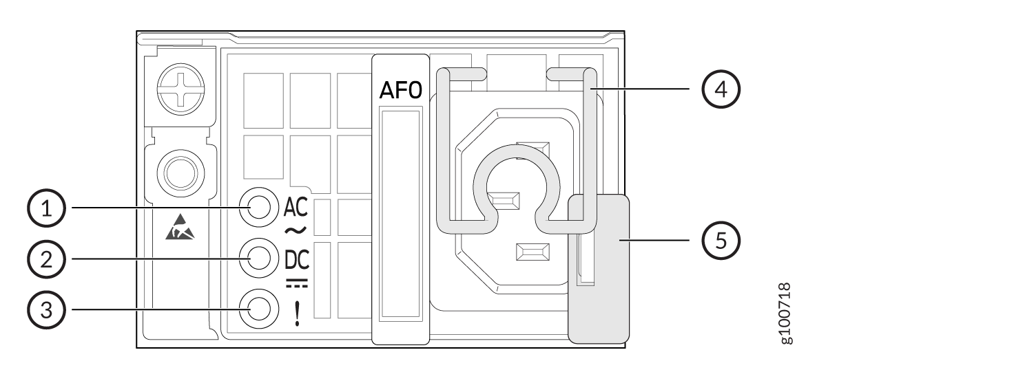
AC Power Supply LEDs on ACX5400 Routers
Figure 14 shows the location of the LEDs on the ACX5448 power supply module (PSM).
1 — Input status LED | 3 — Fault LED |
2 — Output status LED |
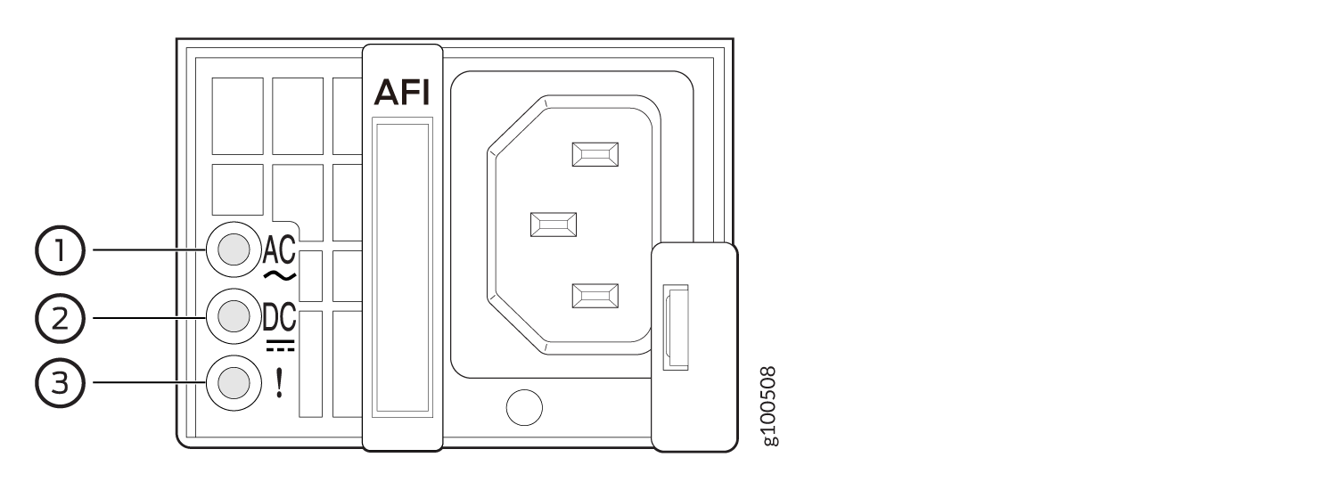
Figure 15 shows the location of the LEDs on the ACX5448-D and ACX5448-M PSM (see callouts 1, 2, and 3).
1 — Input status LED | 3 — Fault LED |
2 — Output status LED |
Table 7 describes the LEDs on the AC PSMs.
|
LED |
Color |
State |
Description |
|---|---|---|---|
|
AC |
Unlit |
Off |
There is no input power to the PSM. |
|
Green |
On steadily |
There is input AC power to the PSM |
|
|
DC |
Unlit |
Off |
There is no output voltage from the PSM. Check the PSM. |
|
Green |
On steadily |
There is output voltage from the PSM. |
|
|
! (fault) |
Amber |
On steadily |
An error is detected in the PSM. Replace the PSM as soon as possible. To maintain proper airflow through the chassis, leave the PSM installed in the chassis until you are ready to replace it. |
If the AC OK LED and the DC OK LED are unlit, either the AC power cord is not installed properly or the power supply fuse has failed. If the AC OK LED is lit and the DC OK LED is unlit, the AC PSM is installed properly, but the power supply has an internal failure.
DC Power Supply LEDs on ACX5400 Routers
Figure 16 shows the location of the LEDs on the DC PSM.
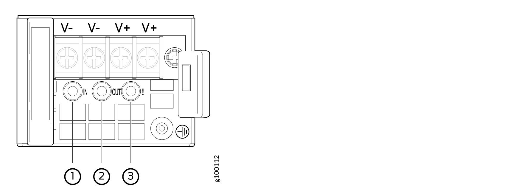
1 — Input LED | 3 — Fault LED |
2 — Output LED |
The V+ terminals are shunted internally, as are the V– terminals. The same polarity terminal can be wired together from the same source to provide an additional current path in a higher-power chassis. Do not connect the terminals to different sources.
Table 8 describes the LEDs on the DC PSMs.
|
Name |
Color |
State |
Description |
|---|---|---|---|
|
IN (input) |
Unlit |
Off |
There is no input power to the PSM. |
|
Green |
On steadily |
There is input DC power to the PSM. |
|
|
OUT (output) |
Unlit |
Off |
There is no output voltage from the PSM. Check the PSM. |
|
Green |
On steadily |
There is output voltage from the PSM. |
|
|
! (fault) |
Amber |
On steadily |
An error is detected in the PSM. Replace the PSM as soon as possible. To maintain proper airflow through the chassis, leave the PSM installed in the chassis until you are ready to replace it. |