Help us improve your experience.

Let us know what you think.

Do you have time for a two-minute survey?


Connecting the ACX2200 to Power

Connecting the ACX2200 Router to Earth Ground

To ground the router, you need the following tools:

  • Phillips (+) screwdriver, number 2

  • ESD grounding wrist strap

  • Two SAE 10-32 screws and flat washers (not provided)

  • Grounding lug, Panduit LCD6-14BH-L or equivalent (not provided)

  • Grounding cable, minimum 16 AWG (1.31 mm2) 90° C wire (not provided)

You must install the ACX2200 in a restricted-access location and ensure that the chassis is always properly grounded. The ACX2200 has a two-hole protective grounding terminal provided on the chassis. See Figure 1. Under all circumstances, use this grounding connection to ground the chassis. For AC-powered systems, you must also use the grounding wire in the AC power cord along with the two-hole grounding lug connection. This tested system meets or exceeds all applicable EMC regulatory requirements with the two-hole protective grounding terminal.

To ground the router:
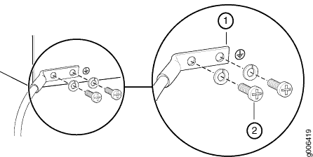
  1. Verify that a licensed electrician has attached the cable lug provided with the router to the grounding cable.
  2. Attach an electrostatic discharge (ESD) grounding strap to your bare wrist, and connect the strap to an approved site ESD grounding point. See the instructions for your site.
  3. Ensure that all grounding surfaces are clean and brought to a bright finish before grounding connections are made.
  4. Connect the grounding cable to a proper earth ground.
  5. Detach the ESD grounding strap from the site ESD grounding point.
  6. Attach an electrostatic discharge (ESD) grounding strap to your bare wrist, and connect the strap to one of the ESD points on the chassis.
  7. Place the grounding cable lug over the grounding points on the front of the chassis (see Figure 1).
  8. Secure the grounding cable lug with the washers and screws. The holes are sized for SAE 10-32 screws. Apply 4 lb-in. (0.49 Nm) of torque to each screw. Do not overtighten the screw. (Use a number 2 Phillips screwdriver.)
    CAUTION:

    Ensure that each grounding cable lug seats flush against the surface of the grounding points as you are tightening the screws. Ensure that each screw is properly threaded into the grounding points. Applying installation torque to the screw when improperly threaded may result in damage to the terminal.

    CAUTION:

    The maximum torque rating of the grounding screws on the router is 4 lb-in. (0.49 Nm). The grounding screws may be damaged if excessive torque is applied. Use only a torque-controlled driver to tighten screws. Use an appropriately sized driver, with a maximum torque capacity of 5 lb-in. or less. Ensure that the driver is undamaged and properly calibrated and that you have been trained in its use. You may wish to use a driver that is designed to prevent overtorque when the preset torque level is achieved.

  9. Dress the grounding cable, and verify that it does not touch or block access to router components, and that it does not drape where people could trip on it.
Figure 1: Grounding Points on the ACX2200 RouterGrounding Points on the ACX2200 Router
  1

Grounding lug

  2

SAE 10-32 screws and washers

Connecting AC Power Cords to the ACX2200 Router

To connect AC power to the router, you need the following tools:

  • ESD grounding wrist strap

  • AC power cords

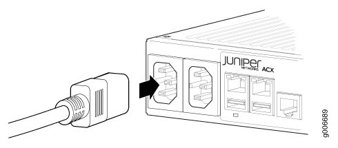
To connect AC power cords to the router:

  1. Locate the power cords, which should have a plug appropriate for your geographical location. See the ACX2200 AC Power Specifications.
  2. Attach an electrostatic discharge (ESD) grounding strap to your bare wrist, and connect the strap to one of the ESD points on the chassis.
  3. Insert the appliance coupler end of the power cord into the appliance inlet on the power supply.
  4. Insert the power cord plug into an external AC power source receptacle.
    Note:

    Each power supply must be connected to a dedicated AC power feed and a dedicated customer site circuit breaker. We recommend that you use a dedicated customer site circuit breaker rated for 2 A (100 VAC) or 1 A (240 VAC), or as required by local code.

  5. Dress the power cord appropriately. Verify that the power cord does not block the air exhaust and access to router components, or drape where people could trip on it.
  6. Repeat Step 1 through Step 5 for the remaining power supplies.
  7. Observe the system LED on the router. If an AC power supply is functioning normally, the system LED lights green steadily. If the system LED is not lit, the power supply is not functioning normally. Repeat the cabling procedures.
    Figure 2: Connecting AC Power to the RouterConnecting AC Power to the Router

Connecting DC Power Cables to the ACX2200 Router

To connect power to the router, you need the following tools:

  • Phillips (+) screwdriver, number 2

  • ESD grounding wrist strap

  • M3 screws and flat washers

  • DC power source cables, minimum 14 AWG or as required by local code (not provided)

  • Ring lugs, Molex 190700067 or equivalent (not provided)

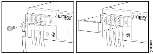
The DC power supply has four terminals on the front panel, covered by a clear plastic cover.

Warning:

You must ground the router before connecting the DC power cables.

To connect the power cables:

  1. Switch off the dedicated customer site circuit breakers. Ensure that the voltage across the DC power source cable leads is 0 V and that there is no chance that the cable leads might become active during installation.
  2. Remove the clear plastic cover protecting the terminal on the faceplate.
  3. Verify that the DC power cables are correctly labeled before making connections to the power supply. In a typical power distribution scheme where the return is connected to chassis ground at the battery plant, you can use a multimeter to verify the resistance of the –48V and return DC cables to chassis ground:

    For –48V and –60V:

    1. The cable with very large resistance (indicating an open circuit) to chassis ground is the DC input cable ().

    2. The cable with very low resistance (indicating a closed circuit) to chassis ground is the return cable (+).

    For +24V:

    1. The cable with very low resistance (indicating a closed circuit) to chassis ground is the DC input cable ().

    2. The cable with very large resistance (indicating an open circuit) to chassis ground is the return cable (+).

  4. Install heat-shrink tubing insulation around the power cables.

    To install heat-shrink tubing:

    1. Slide the tubing over the portion of the cable where it is attached to the lug barrel. Ensure that tubing covers the end of the wire and the barrel of the lug attached to it.

    2. Shrink the tubing with a heat gun. Ensure that you heat all sides of the tubing evenly so that it shrinks around the cable tightly.

    Figure 3 shows the steps to install heat-shrink tubing.

    Note:

    Do not overheat the tubing.

    Figure 3: How to Install Heat-Shrink Tubing
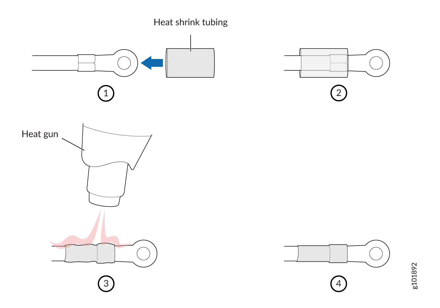
 How to Install Heat-Shrink Tubing
  5. Remove the screws and flat washers from the terminals.
  6. Secure each power cable lug to the terminal with the flat washers and screw (see Figure 4). Apply between 8 lb-in. (0.9 Nm) and 9 lb-in. (1.02 Nm) of torque to each screw. Do not overtighten the screw. (Use a number 2 Phillips screwdriver.)
    1. Secure the positive DC source power cable lug to the return (+) terminal.

    2. Secure the negative DC source power cable lug to the input () terminal.

    CAUTION:

    Ensure that each power cable lug seats flush against the surface of the terminal block as you are tightening the screws. Ensure that each screw is properly threaded into the terminal. Applying installation torque to the screw when improperly threaded may result in damage to the terminal.

    CAUTION:

    The maximum torque rating of the terminal screws on the DC power supply is 9 lb-in. (1.02 Nm). The terminal screws may be damaged if excessive torque is applied. Use only a torque-controlled driver to tighten screws on the DC power supply terminals. Use an appropriately sized driver, with a maximum torque capacity of 9 lb-in. or less. Ensure that the driver is undamaged and properly calibrated and that you have been trained in its use. You may wish to use a driver that is designed to prevent overtorque when the preset torque level is achieved.

  7. Replace the clear plastic cover over the terminals on the faceplate.
  8. Attach an electrostatic discharge (ESD) grounding strap to your bare wrist, and connect the strap to an approved site ESD grounding point. See the instructions for your site.
  9. Connect each DC power cable to the appropriate external DC power source.
    Note:

    For information about connecting to external DC power sources, see the instructions for your site.

  10. Switch on the external circuit breakers to provide voltage to the DC power source cable leads. Observe the system LED on front of the router. If the DC power cable is correctly installed and functioning normally, the system LED lights green steadily. If the system LED indicates that the power supply is not functioning normally, repeat the installation and cabling procedures.
Figure 4: Connecting DC Power to the RouterConnecting DC Power to the Router