Know Your 100G Transceiver
100 Gigabit Ethernet (100G) transceivers are optical modules that handle data rates of 100 Gbps. With a transmission rate of up to 100 Gbps, 100G transceivers serve as essential components for transceiver requirements in many networks. Juniper Networks' 100G transceivers use the C Form-Factor Pluggable (CFP), C Form-Factor Pluggable 2 (CFP2), Quad Small Form-Factor Pluggable 28 (QSFP-28), Small Form-Factor Pluggable 56 Double Density (SFP56-DD), Small Form-Factor Pluggable 112 (SFP112), and Small Form-Factor Pluggable Double Density (SFP-DD) form factors. 100G transceivers are suitable for:
-
Host platforms with 100G ports
-
Networks with 100 Gbps data transmission
-
Data center deployments
100G transceivers use multiple lanes of optical signals and advanced modulation techniques for higher capacity. These transceivers can employ multiplexing techniques—such as parallel optics or wavelength multiplexing—to transmit signals efficiently, with many implementations favoring wavelength multiplexing.
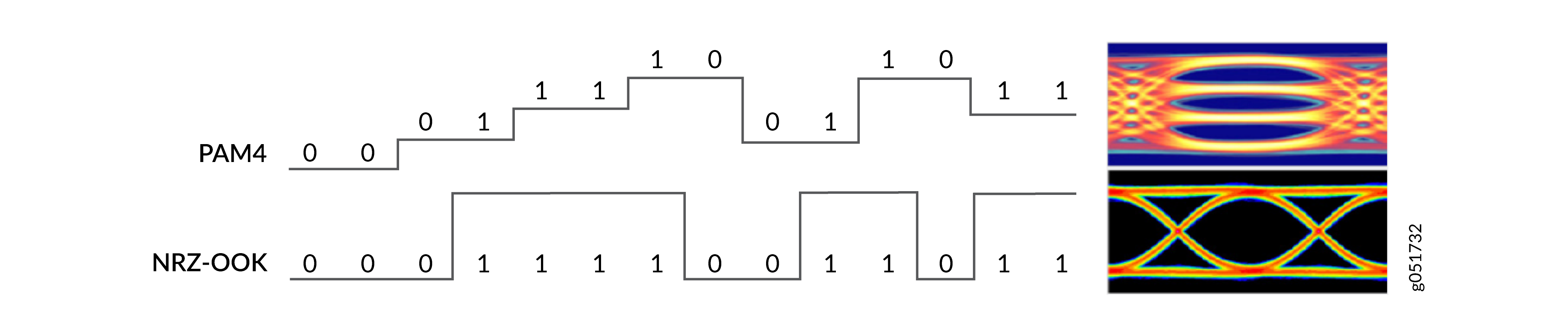
100G transceivers commonly feature a four-lane architecture, with each lane operating at 25 Gbps. SFP-DD and SFP56-DD transceivers use a two-lane architecture with each lane operating at 50 Gbps. The 100G transceivers use Non-Return to Zero (NRZ-OOK) or Pulse Amplitude Modulation 4-level (PAM4) modulation schemes. The PAM4 modulation scheme enables doubling the data rate per lane compared to traditional NRZ, which supports 100G transmissions with fewer lanes and fibers.
100G transceivers support multiple transmission rates and breakout modes to ensure compatibility with various network transport requirements. Design flexibility allows a single physical transceiver to be logically divided into multiple lower-speed Ethernet ports, adapting to different deployment scenarios:
-
1x100G—The transceiver operates as a single 100G port without breakout. This configuration is supported by SFP56-DD, SFP-DD, and QSFP28 form factors.
-
4x25G—The transceiver can break out into four separate 25G ports. The transceiver uses QSFP28 form factor that supports division of 100G transmission into four lower-speed lanes or ports of 25G each.
-
10x10G—The transceiver can break out into ten separate 10G ports. The transceiver module uses the form factor CFP (C represents the Roman numeral for 100) that supports division of the 100G transmission into ten lower-speed lanes or ports of 10G each.
SFP-DD and SFP56-DD modules provide 100G in a single-port configuration and don't support breakout modes. They only have two lanes (2×50G).
2x50G breakout is possible with certain Direct Attach Copper (DAC) and Active Optical Cable (AOC) assemblies. Standard 100G optical transceivers don’t support 2x50G breakout. Exceptions include 100G SR1P2 and 100G BXSR.
100G Optical Transceiver Flavors
You can have various 100G optical transceiver flavors, depending on their electrical interface and optical interface configurations.
Electrical Interfaces
-
One-Lane Electrical Interface (100GAUI-1)
- The 100GAUI-1 electrical interface uses a single high-speed lane operating at 100G.
- These ASICs use 100G Serializer/Deserializer (SerDes) for native 100G support (PAM4 modulation).
- The 100GAUI-1 interface is used with SFP112 modules (when available). It's also used in single-lane 100G QSFP28 modules (DR1, FR1, LR1), and the host provides a single 100G electrical lane.
-
Two-Lane Electrical Interface (100GAUI-2)
-
The 100GAUI-2 electrical interface uses two high-speed lanes.
-
These ASICs use 50G SerDes for native 100G support. The 2x50G electrical interface between the host and the pluggable optic is necessary.
-
The two-lane interface is used with SFP56-DD and SFP-DD optics.
-
- Four-Lane Electrical Interface (100GAUI-4 and CAUI-4)
- The electrical interface uses four high-speed lanes.
- These ASICs use 25G SerDes for native 100G support. The 4x25G electrical interface between the host and the pluggable optic is necessary.
- The four-lane interface is used with QSFP28 optics.
-
Four-lane electrical interface has two variants:
-
100GAUI-4—A newer standard that uses KR4 Forward Error Correction (KR4 FEC). Optics such as 100G SR4, ER4L, and 4WDM-40 use 100GAUI-4.
-
CAUI-4—A legacy standard that does not use FEC. Optics such as 100G LR4 use CAUI-4.
-
- Ten-Lane Electrical Interface (CAUI-10)
- The CAUI-10 interface incorporates ten electrical lanes for data transmission.
- It's supported by legacy PFE ASICs and early 100G implementations.
- These ASICs employ 10G SerDes for native 100G support. The 10x10G electrical interface between the host and the pluggable optic is necessary.
- Ten-lane electrical interface is used with CFP or CFP2 optics.
| Electrical Interface | Number of Lanes | Lane Speed | FEC Support | Form Factors | Example Optics |
|---|---|---|---|---|---|
| 100GAUI-1 (1x100G) | 1 | 100G (PAM4) | Yes | QSFP28 (single-lane), SFP112 (when available) | Single-lane 100G optics |
| 100GAUI-2 (2x50G) | 2 | 50G (PAM4) | Yes | SFP56-DD, SFP-DD | 100G-DR1, 100G-FR1, 100G-LR1 |
| 100GAUI-4 (4x25G) | 4 | 25G (NRZ) | Yes (KR4 FEC) | QSFP28 | 100G-SR4, 100G-ER4L, 100G-CWDM4, 100G-4WDM-40 |
| CAUI-4 (4x25G) | 4 | 25G (NRZ) | No | QSFP28 | 100G-LR4 (legacy) |
| CAUI-10 (10x10G) | 10 | 10G (NRZ) | No | CFP, CFP2 | 100G-LR10, 100G-ER10 (legacy) |
Optical Interfaces
- Single-Lane Optical Interface (1x100G)
- The single-lane optical interface uses a single optical lane operating at 100 Gbps with PAM4 modulation.
-
This interface requires only duplex fiber (one transmit, one receive) using duplex LC connectors.
- This interface is available in multiple distance ranges—DR1, FR1, LR1, ER1 (500 m to 40 km over single-mode fiber).
- It is supported by SFP56-DD, SFP-DD and QSFP28 form factors.
-
It is interoperable with 400G optics by using breakout cables.
-
Juniper commonly supports the following single-wavelength 100G optical interfaces:
-
SDD-100G-DR (100G-DR1)—Single wavelength, 500 meters reach over single-mode fiber using SFP56-DD or SFP-DD form factor.
- QSFP-100G-DR (100G-DR1)—Single wavelength, 500 m reach over single-mode fiber.
- QSFP-100G-FR (100G-FR1)—Single wavelength, 2 km reach over single-mode fiber.
- QSFP-100G-LR (100G-LR1)—Single wavelength, 10 km reach over single-mode fiber.
-
-
Two-Lane Optical Interface (2x50G)
-
Two-lane optical interface uses two optical lanes, each operating at 50 Gbps.
-
The design is optimized for multimode fiber deployments.
-
The fiber count is lower in comparison to four-lane solutions.
-
Juniper commonly supports the following two-lane 100G optical interfaces:
-
JNP-QSFP-100G-BXSR (QSFP28 form factor)—Bidirectional transmission using two wavelengths over multimode fiber, 100 m reach (OM4), uses 2 fibers (duplex LC PC/UPC connector).
- QSFP-100G-SR1P2 (QSFP28 form factor)—Two wavelengths over multimode fiber, 100 m reach (OM3, OM4. OM5), uses 2 fibers (duplex LC PC/UPC connector).
-
-
-
Four-Lane Optical Interface (4x25G)
- SR4—Parallel multimode cables with 8 fibers with a maximum reach of up to 70 m (OM3) or 100 m (OM4). SR4 is used within data center environments.
- LR4—Duplex single-mode fiber with a maximum reach of up to 10 km.
- ER4—Duplex single-mode fiber with a maximum reach of up to 40 km.
-
CWDM4—Uses duplex single-mode fiber with coarse wavelength spacing and has a maximum reach of up to 2 km.
-
Ten-Lane Optical Interface (10x10G)
SR10—Primarily focused on short-reach applications using multimode fibers with 20 fibers (10 transmit, 10 receive). As the technology for 100G SR4 matured, SR10 became legacy technology.
Note: We recommend transitioning to 100G SR4 or LR4 optics, which provide better performance and remain relevant.
| Optical Interface | Number of Lanes | Lane Speed | Fiber Type | Connector | Max Reach | Optics (Example) |
|---|---|---|---|---|---|---|
| 1x100G (Single-lane) | 1 | 100G (PAM4) | Single-mode | Duplex LC | 500 m through 10 km | DR1, FR1, LR1 |
| 2x50G (Dual-lane) | 2 | 50G | Multimode | Duplex LC | 100 m | SR1.2, BXSR |
| 4x25G (Quad-lane) | 4 | 25G (NRZ) | Multimode or Single-mode | MPO-12 (SR4) or Duplex LC (LR4, CWDM4) | 70 m through 100 m (SR4), 2 km through 10 km (LR4, CWDM4), 40 km (ER4) text. | SR4, LR4, CWDM4, ER4 |
| 10x10G (Ten-lane) | 10 | 10G (NRZ) | Multimode | MPO-24 | 100 m through 150 m | SR10 (legacy) |
- Fiber count—Single-lane and two-lane use 2 fibers (duplex). Four-lane SR4 uses 8 fibers (parallel). Four-lane LR4/CWDM4 use 2 fibers (WDM). Ten-lane uses 20 fibers.
- Modulation—PAM4 for single-lane, NRZ for two-lane, four-lane, and ten-lane.
- Wavelength type—Single wavelength (DR1, SR4), WDM multiplexing (LR4, CWDM4), bidirectional (BXSR, SR1.2).
| Property | Single-Lane (DR1/FR1/LR1) | Two-Lane (SR1.2/BXSR) | Four-Lane (SR4) | Four-Lane (LR4/CWDM4/ER4) | Ten-Lane (SR10) |
|---|---|---|---|---|---|
| Optical Lanes | 1 | 2 | 4 | 4 | 10 |
| Optical Lane Speed | 100 Gbps (PAM4) | 50 Gbps each | 25 Gbps each (NRZ) | 25 Gbps each (NRZ) | 10 Gbps each (NRZ) |
| Symbol Rate (Baud) | ~53.125 GBd | ~26.5625 GBd per lane | ~25.78125 GBd per lane | ~25.78125 GBd per lane | ~10.3125 GBd per lane |
| Electrical Interface | 100GAUI-2 (2x50G) for SFP-DD | 100GAUI-2 (2x50G) | 100GAUI-4 (4x25G) with KR4 FEC |
CAUI-4 (4x25G) without FEC (LR4) 100GAUI-4 (4x25G) with KR4 FEC (CWDM4, ER4L) |
CAUI-10 (10x10G) without FEC |
| Fiber Type | Single-mode | Multimode (OM3/OM4/OM5) | Multimode (OM3/OM4) | Single-mode | Multimode |
| Fiber Count | 2 (duplex) | 2 (duplex) | 8 (4 Tx + 4 Rx) | 2 (duplex) | 20 (10 Tx + 10 Rx) |
| Connector Type | Duplex LC | Duplex LC | MPO-12 (8 fibers used, 4 unused) | Duplex LC | MPO-24 |
| Wavelength Technology | Single wavelength | Bidirectional | Parallel optics | LAN WDM | Parallel optics |
| Reach |
DR1—500 m FR1—2 km LR1—10 km |
SR1.2—70 m (OM3), 100 m (OM4), 150 m (OM5) BXSR—100 m (OM4) |
70 m (OM3) 100 m (OM4) |
LR4—10 km ER4—40 km ER4L—40 km (with FEC) or 30 km (without FEC) |
100 m (OM3) 150 m (OM4) |
| Form Factor | SFP56-DD, SFP-DD, QSFP28 | QSFP28 | QSFP28 | QSFP28 | CFP, CFP2 |
| FEC Support | Yes (RS-FEC) | Yes (RS-FEC) | Yes (KR4 FEC on electrical, RS-FEC on optical) |
LR4—No ER4L—Yes (KR4 FEC) |
No |
| Breakout Support | Yes (interoperable with 400G using breakout cables) | No | Yes (4x25G breakout) | Yes (4x25G breakout) | No |
| Modulation | PAM4 | PAM4 (optical lanes) | NRZ | NRZ | NRZ |
| IEEE Standard |
IEEE 802.3cd-2018 IEEE 802.3-2022 |
IEEE 802.3cd-2018 |
IEEE 802.3ba-2010 IEEE 802.3bm-2015 |
IEEE 802.3ba-2010 IEEE 802.3bm-2015 |
IEEE 802.3ba-2010 |
Modulation Methods
Pulse Amplitude Modulation 4-level (PAM4)—PAM4 is a four-level modulation format increasingly used in 100G optical transceivers, especially in shorter-reach, cost-sensitive scenarios such as data center interconnects. Each of the four amplitude levels represents two bits of data. This approach effectively doubles the data rate per lane compared to NRZ without requiring faster optical components. However, PAM4 reduces the distance between adjacent signal levels to one-third that of NRZ. This approach results in a theoretical Signal-to-Noise Ratio (SNR) penalty of approximately 9.5 dB (20 × log(1/3)). This reduction in SNR necessitates advanced Digital Signal Processing (DSP) and robust FEC to maintain link performance.
Non-Return-to-Zero On-Off Keying (NRZ-OOK) Modulation—NRZ is a fundamental binary modulation format used in many 100G optical transceivers, especially in implementations with multiple lanes at 25 Gbps or 10 Gbps per lane. In NRZ modulation, binary data is represented by two distinct signal levels—high and low—where each level corresponds to one bit (0 or 1). The signal doesn't return to zero between consecutive bits of the same value, so it's call "non-return-to-zero." NRZ provides good SNR performance due to the maximum separation between two signal levels, which is suitable for longer reaches or lower-complexity 100G systems.
FEC is a channel-coding technique that supports signal integrity. FEC transmits data with redundancies. FEC is necessary for ensuring signal integrity in 100G optical communications, particularly when using PAM4 modulation. FEC encodes data with redundancy. This redundancy allows the receiver to detect and correct errors without retransmission.
FECs are implemented through FEC algorithms. FEC algorithms are specific mathematical techniques or coding schemes. FEC algorithms detect and correct errors in transmitted data without requiring retransmission. The FEC process includes two steps:
-
Encoding at the Tx or transmitter—The FEC algorithm processes the original data and adds redundant bits or parity bits based on a specific mathematical rule. The system then transmits the encoded data over the communication channel.
-
Decoding at the Rx or Receiver—The receiver uses the FEC algorithm to analyze the received data, including the redundant bits. If the receiver detects errors, the algorithm corrects them based on redundancy.
The error correction capability of FEC depends on the specific algorithm used and the amount of redundancy added. For 100G optical transceivers, the industry standardized FEC codes are:
-
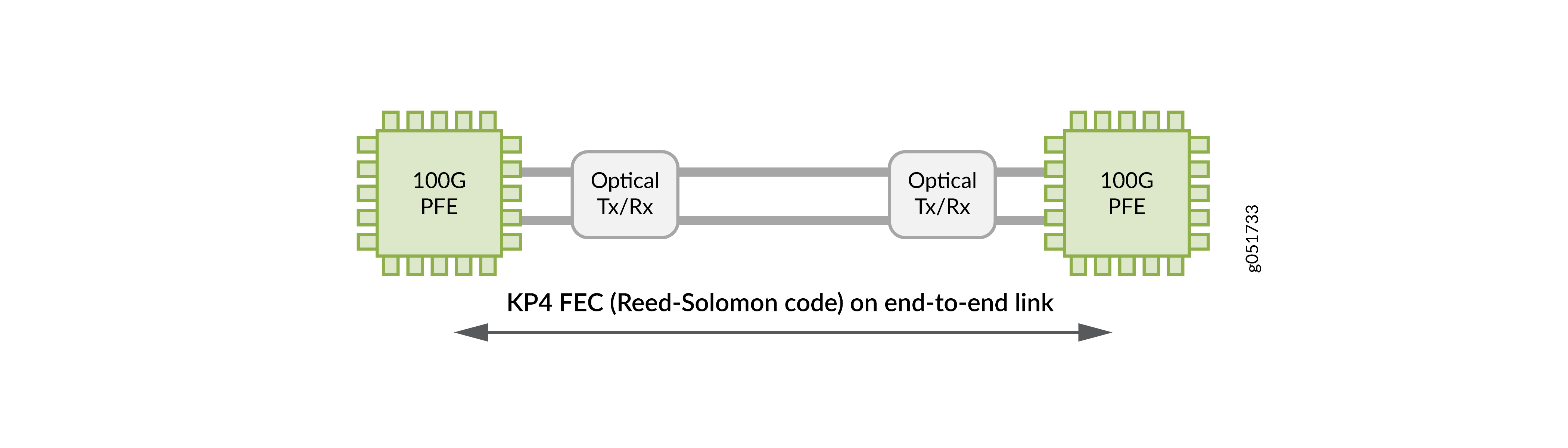
RS(528,514)—RS(528,514) is standardized in 100GBASE-KR4 for 100G over copper backplanes using NRZ-OOK modulation. RS(528,514) is often called KR4 FEC.
-
RS(544, 514) or FEC119—RS(544, 514) is standardized in 100GBASE-KP4 for 100G over copper backplanes using PAM4 modulation. RS(528,514) is often called KP4 FEC.
100G optics also use the following technologies:
-
DSP techniques—Not all 100G transceivers use advanced DSP techniques. Many standard 100G transceivers, especially shorter-reach variants like SR4, rely on simpler analog processing. DSP enhances signal integrity and extends the reach of certain 100G transceivers over optical fiber. Basic 100G optical transceivers (such as CFP-100GBASE-SR10, CFP2-100GBASE-LR4, and CFP2-100GBASE-ER4) typically use simpler analog processing. Functions such as Feed-Forward Equalization (FFE), Decision Feedback Equalization (DFE), and Clock Data Recovery (CDR) are used in 100G optics to ensure signal integrity in both electrical and optical signaling. DSP involves several components such as:
-
SerDes—SerDes converts data between serial and parallel forms, enabling efficient and high-speed data transfer within the optic. The SerDes device works closely with the DSP to manage data flow and conversion.
-
FFE and DFE—FFE and DFE mitigate inter-symbol interference (ISI) and enhance signal clarity. FFE addresses linear distortions before a decision is made. DFE helps correct errors based on previously received symbols, working dynamically to improve overall signal quality.
-
-
CDR—CDR extracts timing information from a data signal and ensures accurate data retrieval and transmission in an optic network.
See the Hardware Compatibility Tool for the list of transceivers, their specifications, and the list of devices supported by the transceivers.
Key Characteristics
The following are the key design considerations for a 100G transceiver:
-
Form factor—Juniper's 100G optical transceivers incorporate multiple form factors to meet different power, thermal, and port density requirements for 100 Gbps data transmission. The primary form factors include:
-
CFP (C Form-factor Pluggable)
-
CFP2 (C Form-factor Pluggable 2)
-
QSFP-28 (Quad Small Form-factor Pluggable 28)
-
SFP56-DD (Small Form-factor Pluggable 56 Double Density)
-
SFP-DD (Small Form-factor Pluggable Double Density)
-
-
Fiber type and reach—The fiber type specifies the type of optical fiber (single-mode or multimode) compatible with 100G transceivers. The reach provides the maximum supported distance or range for an optical transceiver. It helps you to select the appropriate optical transceiver for different applications, such as inter-data center, intra-data center, long-haul networks, and so on.
-
Lane distribution—IEEE 802.3ba defines lane distribution. Lane distribution happens in the PCS, and lanes are then multiplexed to 4 or 10 lanes in the PMD depending on the exact optics type. The types of lane distribution include:
-
Single lane—In a single-lane configuration, the entire Ethernet signal is conveyed through one optical lane or channel.
-
Multiple lanes—Multiple lane distribution leverages parallel optical transmission by stripping Ethernet signals into multiple low rate lanes. The low rate lanes map into optical lanes or channels. This results in a more optimal cost per bit, fewer points of failure and interfaces, and lower power and heating.
100G optics operate with lane rates of 10G or 25G per lane depending on the transceiver type. However, with breakout capabilities, Juniper's 100G optics can offer 2x50G configuration, ensuring that the total bandwidth utilization is 100G. The breakout ports of lower speeds are fully independent and can run on separate time domains, enabling higher density applications.
Figure 3: 4x25G Solution Using Four Wavelengths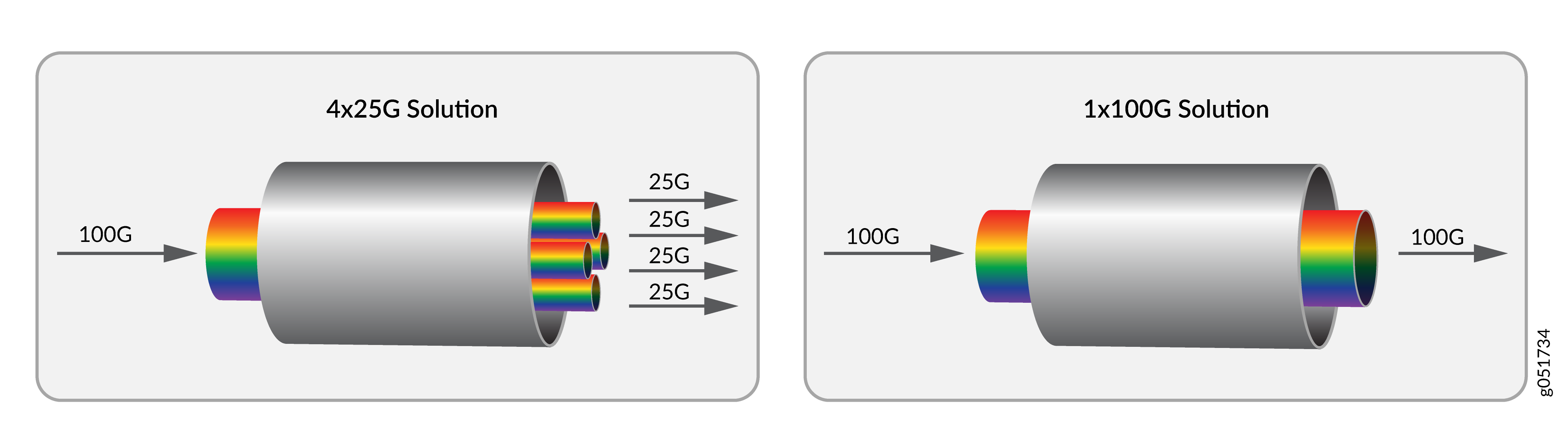
-
Juniper Optical Product Numbers
Juniper's optical components such as transceivers, cables, and connectors follow a naming convention. Each element in the product name corresponds to a specification. It helps you to better understand and select the optical component that you need. For example:
-
QSFP—In context of 100G optics, QSFP denotes QSFP-28 and is short for quad small form-factor pluggable-28. The prefix of Juniper's optical transceivers identifies the form-factor of the transceiver or cable.
-
100G—Indicates that the transceiver is capable of data transfer rates of 100 Gbps.
-
SR4—Stands for 100GBASE-SR4. It is a specific standard that uses four parallel lanes of 25 Gbps to deliver 100 Gbps over multimode fiber for short-reach applications (up to 70 meters on OM3 fiber or 100 meters on OM4 fiber).
-
C—The symbol C indicates that the SKU belongs to Juniper’s common optics portfolio.
You can distinguish the Juniper optical cables from transceivers using the product numbers. For example, QSFP-100G-DAC-50CM and SDD-100G-1M (Juniper cables) specify the cable type (DAC) and distance range (50 centimeters or 1 meter) in their product names.
100G (X4) Transceiver Architecture
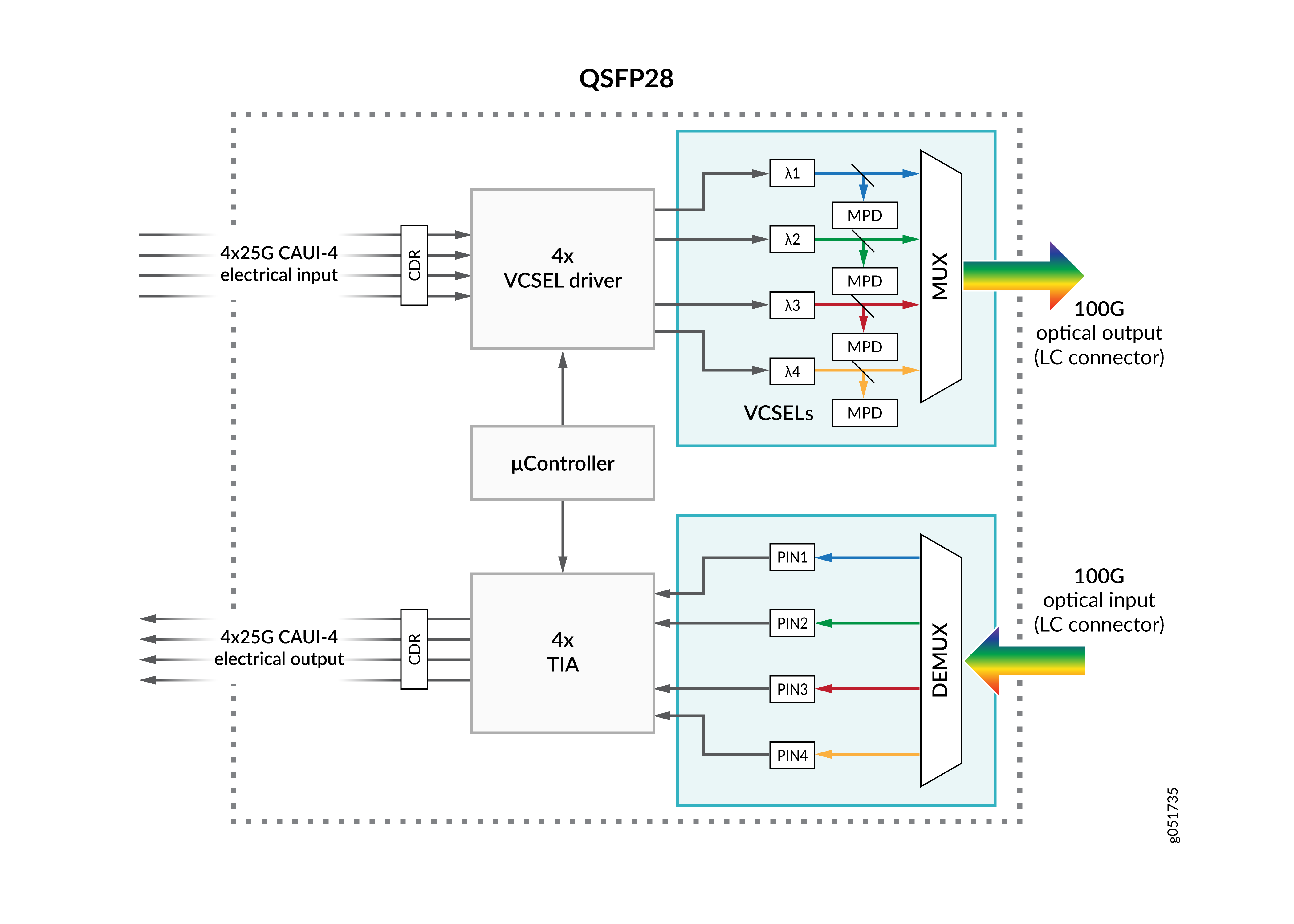
The industry-standard and most widely deployed design for 100G transceivers uses a four-lane 4x25G NRZ electrical interface (100GAUI-4) on the host side. X4 denotes the four-lane electrical interface. The host side represents the part of the transceiver that connects to the switch, router, or any other host device. On the line side, the 100G transceivers uses a four-lane 4x25G NRZ optical interface (100G-SR4). The line side represents the part of the transceiver that transmits and receives data over fiber cables to the network.
This architecture is used in 100G transceiver form factors like QSFP28. The following are the different components of a 100G transceiver architecture:
- 100G platform—The Juniper device (switch or router) that supports the 100G architecture.
- 4x25 Gbps electrical—The electrical interface between the switch and the transceiver components. It can transmit data over four separate 25 Gbps electrical lanes.
- 4x25 Gbps optical—The optical interface between the transceiver and the network. It can transmit data over four separate 25 Gbps optical lanes.
- DSP—The 100G DSP performs signal conditioning and conversion between the 4x25G electrical lanes and the 4x25G optical lanes. NRZ effectively provides reliable data transmission at 25G per lane. The CDR is responsible for re-timing incoming data to reduce jitter. The DSP handles functions like equalization, error correction, and other signal processing tasks.
- Driver—Drivers are electronic components that amplify the electrical signal. The x4 transceiver architecture has four drivers. Each driver corresponds to a 25G lane.
- Directly modulated laser (DML)—Modulated lasers convert the amplified electrical signals into optical signals. It includes Vertical-Cavity Surface-Emitting Lasers (VCSELs) for multimode applications and DMLs for single-mode applications.
- Transimpedance Amplifiers (TIA)—TIA is the receiving end of an optical transmission. It converts the electrical current output of a photodiode to a specific voltage level. It can operate with very low signal levels that are typical for long-distance optical communication.
- Photo-Detector— It works in tandem with the TIA to convert the optical information back into electrical form. For detailed information on photodiode technologies used in 100G transceivers, See Photodiode Types in 100G Optical Transceivers.
Some 100G optical transceivers, such as SR4 modules, use four parallel lanes each running at 25G NRZ, directly converting electrical to optical signals. Some 100G optical transceivers use wavelength division multiplexing to convert 4×25G electrical lanes into multiplexed optical signals. For example, LR4 modules use wavelength division multiplexing, where the four electrical lanes at 25G NRZ are converted into four optical wavelengths (1295.56 nm, 1300.05 nm, 1304.58 nm, 1309.14 nm) multiplexed onto a single fiber pair. This reduces the number of optical fibers required, simplifying cabling and connectors. For example, a 4×25G architecture requires eight fibers for its four lanes, often using MPO connectors or multiple duplex LC connectors. However, a 100G module such as LR4 that uses wavelength division multiplexing requires only two fibers (one duplex LC connector) to transmit and receive signals. Some 100G optical transceivers use bidirectional transmission with gearbox conversion to optimize fiber utilization. For example, BiDi 100G-SR1.2 modules use a 4:2 gearbox, where the four electrical lanes at 25G NRZ are converted into two optical lanes at 50G PAM4 using bidirectional 850 nm or 910 nm wavelengths on duplex LC connectors.
Photodiode Types in 100G Optical Transceivers
100G optical transceivers use two types of photodiodes for converting optical signals back to electrical signals:
-
Positive-intrinsic-negative photodiodes (PIN)—PIN photodiodes are used in short-reach and medium-reach 100G transceivers where optical input power levels are relatively high. PIN photodiodes have a higher damage threshold and are suitable for high input optical power levels. Hence, optics with PIN photodiodes such as LR4, CWDM4, DR, FR1, and LR1 can be connected back-to-back without risk of damage.
-
Avalanche photodiodes (APD)—APDs provide are designed to detect very weak optical signals. They are used in long-reach 100G transceivers where maximum optical sensitivity is critical. Since APDs have a low damage threshold, they can be easily damaged by excessive optical input power. This is particularly applicable on short, low-loss fiber links. Optics with APD photodiodes, such as ER4L, 4WDM40, ZR4, and ER1-40, require external optical attenuators on short links. Attenuators ensure that the optical input power stays below the damage threshold and prevent damage.
The choice of photodiode technology has significant operational implications, particularly regarding optical power handling and link design. Always verify optical power levels before deploying transceivers. Excessive input power can damage photodiodes, especially those using APD. Transceivers used in short distance transmissions receive higher optical power. This power can exceed the damage threshold of your APD transceiver, if not properly attenuated.
For short-reach transmission, we recommend PIN-based transceivers. However, if you are using APD-based transceivers, ensure that you employ appropriate optical attenuators.