
Connector Types
Optical connectors ensure efficient and reliable connections between fiber optic cables. Connectors are designed to minimize insertion loss and back reflection, ensuring high-quality signal transmission.
100G transceivers support the following connector types:
-
MPO-12 APC and MPO-12 PC/UPC—A multifiber push-on (MPO-12) has a single row of connectors with 12 optical fiber channels or lanes. An MPO-12 connector contains four transmission (TX) channels and four reception (RX) channels that are used to transmit and receive signals. Four optic fiber channels are unused or reserved in MPO-12 connectors used with 100G optical transceivers. In a standard deployment, the four unused channels or lanes are those located in the center of the row. MPO-12 PC/UPC is used for parallel multimode optics such as 100G-SR4. MPO-12 APC is used for parallel single-mode optics such as 100G-PSM4.
- APC—Angled physical contact (APC) denotes an optical fiber endface that is polished at an eight-degree angle. APC reduces back reflection by directing reflected light into the fiber cladding rather than back toward the source.
- PC/UPC—Physical contact (PC) or ultra physical contact (UPC) denotes a rounded optical fiber endface that is polished to maintain a very smooth, slightly curved surface (nearly zero degrees). PC/UPC helps to improve contact quality and reduce back reflection compared to other physical contact connectors.
Figure 1: MPO-12 Connector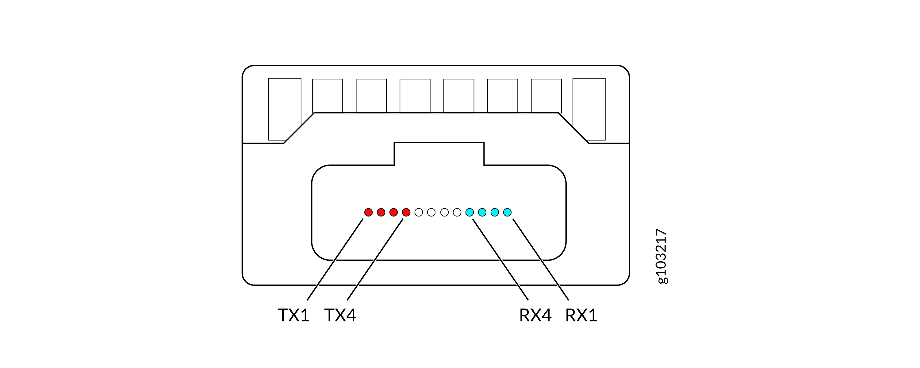
-
MPO-24 PC/UPC—A multi-fiber push-on 24 (MPO-24) connector has 24 optical fibers in a single connector. For example, the 100G-SR10 transceiver uses 20 fibers of the MPO-24 connector. Ten fibers are used as TX (transmit) channels and ten fibers are used as RX (receipt) channels. Each fiber carries a 10G NRZ channel, totaling ten parallel channels per direction for 100G aggregate bandwidth. With physical contact (PC) or ultra physical contact (UPC), the connector minimizes back reflection and ensures better signal integrity. MPO connectors offer high-density connections and support multiple fibers in a single connector. MPO connectors are often used in data centers.
Figure 2: MPO-24 Connector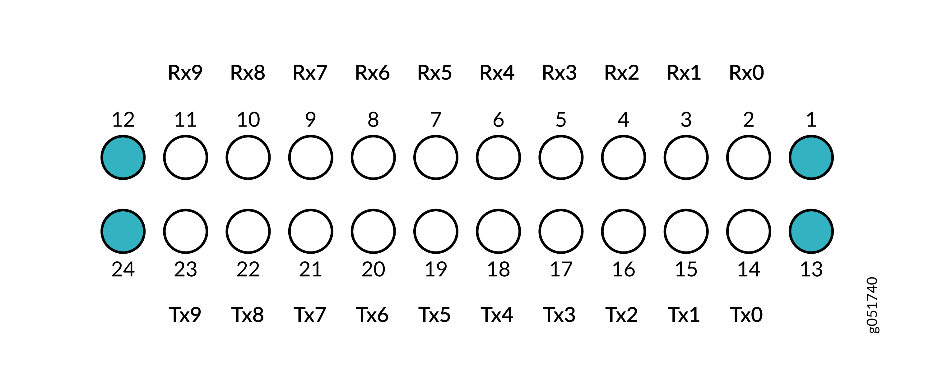
-
Duplex LC PC/UPC—A duplex LC connector is a type of lucent connector (LC) that has small form factor and high-density design. The term duplex indicates that the connector houses two separate fiber optic channels or lanes within a single unit. One channel is for transmission (TX) and the other is for reception (RX). The TX and RX channels enable full-duplex, bidirectional communication over a single connector. The typical LC interface is half the size of the traditional standard connector (SC). The smaller size allows greater port density in patch panels and transceivers. Duplex LC connectors use PC/UPC polish for both multimode and single-mode applications. Like other optical connectors, the duplex LC connector is color-coded. This helps maintain correct polarity and simplifies installation and troubleshooting.
Figure 3: Duplex LC Connector
The image represents the channel or lane allocation for a 100G optical transceiver using duplex LC connector:
-
Red (TX)
-
Blue (RX)
-
-
Simplex LC PC/UPC—A simplex LC connector is a single-fiber lucent connector (LC) with the same small form factor and high-density design as duplex LC. The term simplex indicates that the connector houses a single fiber optic channel within the connector. Simplex LC connectors are used exclusively with bidirectional (BiDi) optical transceivers that transmit and receive on the same fiber using different wavelengths. Simplex LC connectors use PC/UPC polish. They are typically used with single-mode BiDi transceivers such as 100G LRBD and 100G ERBD. LRBD and ERBD require only one fiber strand for full-duplex bidirectional communication.