Know Your 1.6T Transceiver
1.6 Terabit (1.6T) transceivers are optical modules capable of handling data rates of 1.6 Tbps or 1.6T Ethernet. 1.6T transceivers offer double the capacity of their latest predecessor (800G transceivers). These transceivers are ideal for:
-
Any host platform with 1.6T-capable ports
-
Networks with 1.6 terabits data transmission
-
Telecommunication networks that require high-speed data transmission with minimal loss
A 1.6T transceiver uses multiple lanes of optical signals and advanced modulation techniques to achieve higher capacities. 1.6T transceivers employ multiplexing using multiple fibers, along with a combination of fiber and wavelength multiplexing to transmit an optical signal. All 1.6T client optics use 8 lanes of 200G with pulse amplitude modulation 4-level (PAM4) modulation.
1.6T transceivers support multiple transmission rates and breakout modes to ensure compatibility with various network transport requirements. This flexibility allows a single physical transceiver to be logically divided into multiple lower-speed Ethernet ports, adapting to different deployment scenarios. Juniper 1.6T transceivers support the following breakout options:
-
1x1.6T
-
2x800G
-
4x400G
-
8x200G
Juniper 1.6T transceivers use the OSFP1600 form factor, which is further categorized as OSFP (with an integrated heat sink) and OSFP-RHS (with a riding heat sink). Juniper does not currently support the QSFP-DD1600 form factor.
See the Hardware Compatibility Tool for the list of transceivers, their specifications, and the list of devices supported by the transceivers.
Modulation Method
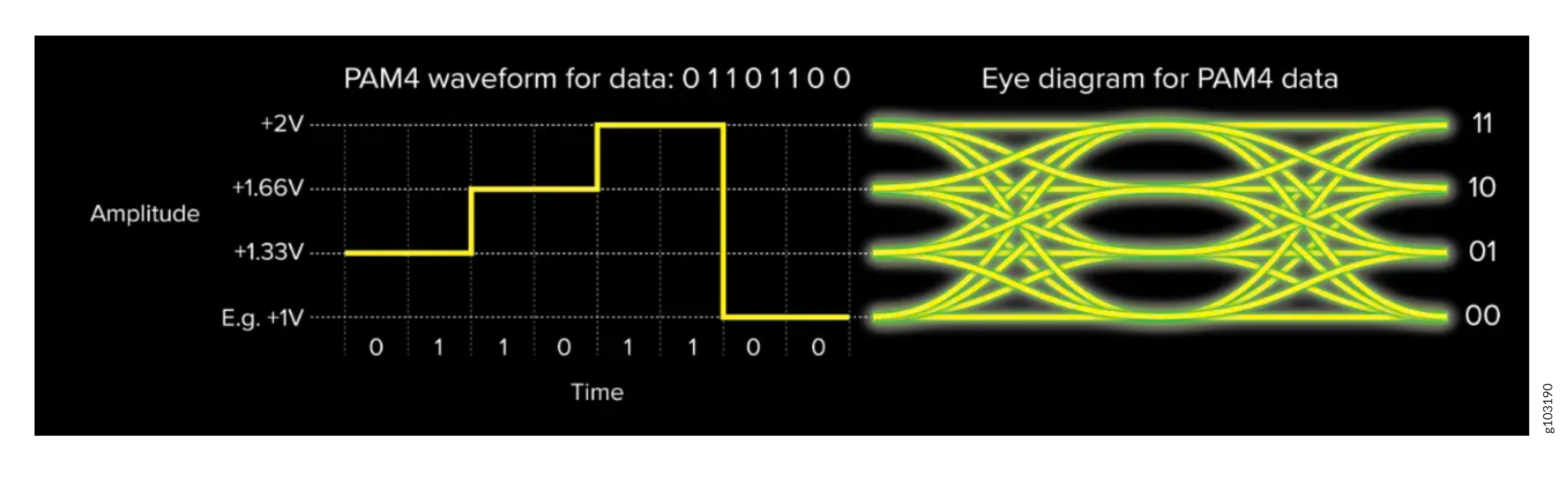
Pulse amplitude modulation 4-level (PAM4) is a modulation method that combines two bits into a single symbol with four amplitude levels, doubling the amount of data transmitted over a network. It enables efficient short distance data transmission, but it demands more signal processing and error correction.
PAM4 has a higher signal to noise ratio (SNR) and is susceptible to internal interference of optical signals over long distances. It is necessary to configure forward error correction (FEC) to handle the signal integrity. You must configure FEC at both the transmitter and receiver ends of a 1.6T communication link. The FEC algorithm encodes data before transmission and decodes and corrects the errors in data upon reception.
Optical Technology
1.6T optics and transceivers use the following technologies:Digital Signal Processing
Advanced digital signal processing (DSP) techniques enhance signal integrity and extend the reach of 1.6T transceivers over optical fiber.
Clock Data Recovery
Clock data recovery (CDR) extracts timing information from a data signal and ensures accurate data retrieval and transmission in an optical network.
Forward Error Correction
1.6T optical transceivers handle high transmission speeds. They are susceptible to errors caused by noise, signal distortions, and nonlinear effects. Forward Error Correction (FEC) is a method of error control in which the transmitter adds redundant data or parity bits to the original data stream. This redundancy allows the receiver to detect and correct errors without requiring retransmission.
FECs are implemented through algorithms, which are specific mathematical techniques or coding schemes. FEC algorithms detect and correct errors in transmitted data without requiring retransmission. The error correction capability of FEC depends on the specific algorithm used and the amount of redundancy added.
The FEC process involves two steps:
-
Encoding (at the Tx or transmitter)—The FEC algorithm processes the original data and adds redundant bits or parity bits based on a specific mathematical rule. The encoded data is then transmitted over the communication channel.
-
Decoding (at the Rx or Receiver)—The receiver uses the FEC algorithm to analyze the received data, including the redundant bits. If errors are detected, the algorithm attempts to correct them based on the redundancy.
1.6T optics use a concatenated FEC scheme, which consists of an inner and an outer error-correcting code. Data is first encoded by the outer code, then re-encoded by the inner code. At the receiver, decoding occurs in reverse.
FEC is implemented both on the networking device (on the PFE) and on the transceiver (on the DSP). This applies to all 1.6T optics with a reach greater than 2 km.
Key Characteristics
The following are the key characteristics of a 1.6T transceiver:
-
Form factor—Juniper supports the OSFP form factor for 1.6T transceivers. OSFP transceiver modules are designed to accommodate the higher power and thermal requirements, handle higher power dissipation, and provide better cooling solutions.
-
Fiber type and reach—The fiber type specifies the type of optical fiber (singlemode or multimode) compatible with 1.6T transceivers. The reach provides the maximum supported distance or range for an optical transceiver. It helps you to select the appropriate optical transceiver for different applications, such as inter-data center, intra-data center and so on.
-
Lane distribution—Juniper's 1.6T optics use eight parallel lanes, either with multiple fiber pairs or wavelength multiplexing. 1.6T optics have parallel fibers that are used over shorter distances. Wavelength multiplexing using duplex single-mode fiber is used for longer distance optical communication.
Juniper Optical Product Numbers
Juniper's optical components such as transceivers, cables, and connectors follow a naming convention. Each element in the product name corresponds to a specification. It helps you to better understand and select the appropriate optical component. For example:
-
ORHS-2x800G-FR4-P
-
ORHS—Short for OSFP with riding heat sink. It identifies the form-factor of the transceiver.
-
2x800G—It indicates that the transceiver supports break-out into two independent 800G Ethernet interfaces for data transmission.
-
FR4—Stands for 800GBase-FR4. It is a specific standard and indicates that each 800G channel uses four parallel lanes of 200 Gbps to deliver 800 Gbps.
-
P—It indicates that the optical connector has a dual configuration (Dual MPO-12/APC or Dual Duplex LC). Without '-P', it indicates a single connector (MPO-16/APC or CS).
-
-
Other transceivers include ORHS-1600G-DR8-2 and ORHS-1600G-DR8-2-P.
1.6T (X8) Transceiver Architecture
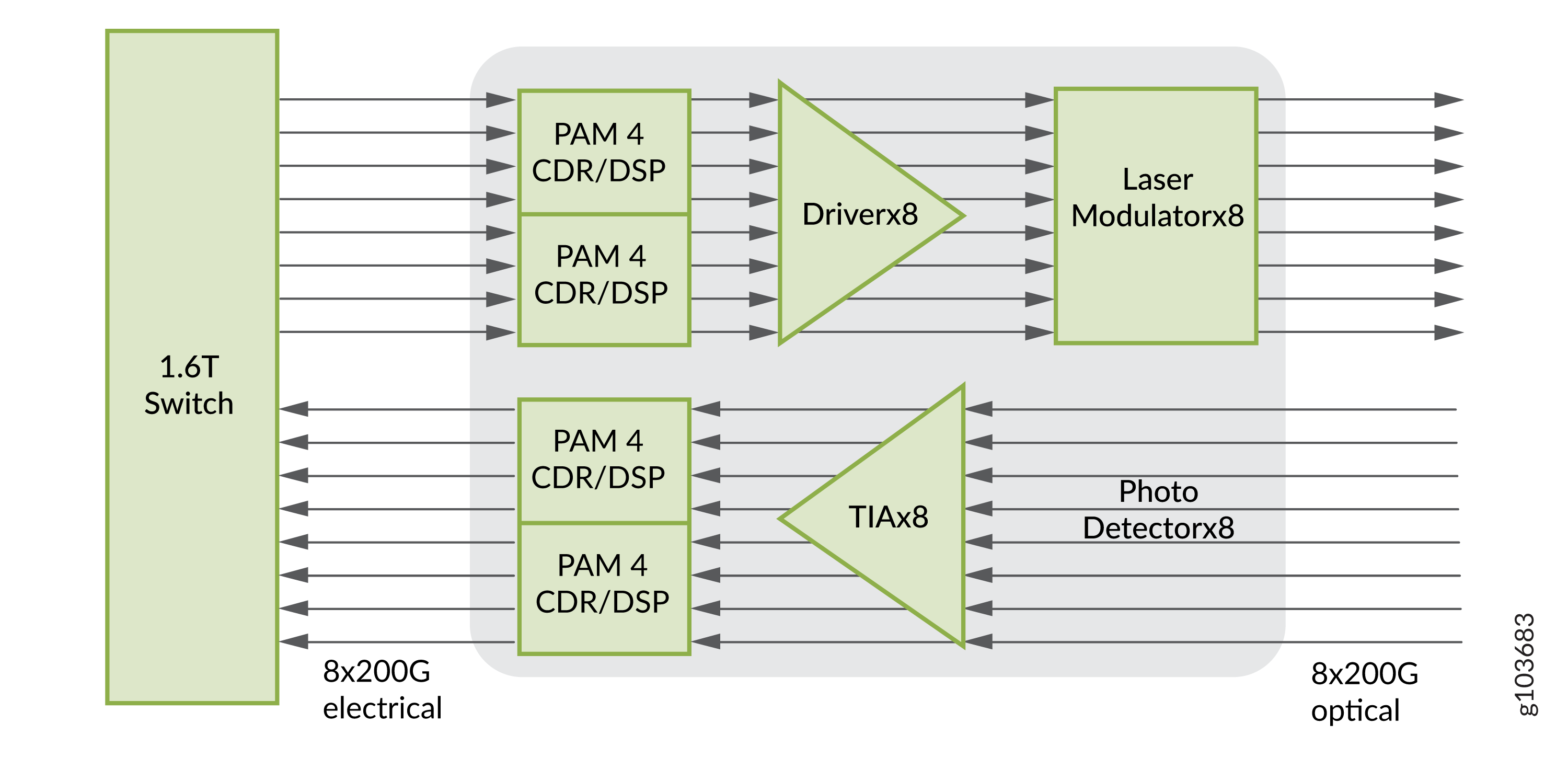
The 8x200 gigabit architecture for a 1.6T transceiver uses eight lanes of 200 Gbps each. The following are the different components of a 1.6T transceiver architecture:
-
Host platforms—Juniper devices that support 1.6T architecture.
-
8x200G electrical—The electrical interface between the switch and the transceiver components. It can transmit data over eight separate 200 Gbps electrical lanes.
-
PAM4 clock data recovery (CDR)/digital signal processor (DSP)—A PAM4 CDR/DSP supports 200 Gbps electrical lanes. PAM4 effectively doubles the amount of data that you can transmit. The CDR is responsible for re-timing incoming data to reduce jitter. The DSP handles functions like equalization, error correction, and other signal processing tasks.
-
Driver x8—Drivers are electronic components that amplify the electrical signal. The x8 transceiver architecture has eight drivers. Each driver corresponds to a 200 Gbps electrical lanes.
-
Modulator x8—Eight modulators correspond to 200 Gbps electrical lanes (x8). 1.6T optics uses the following types of modulators:
-
Vertical cavity surface emitting Lasers (VCSEL)—VCSEL is used for multimode optics such as SR8/VR8.
-
Directly modulated lasers (DMLs)—DMLs are used for single-mode optics such as DR8. DMLs use distributed feedback (DFB) structures that incorporate a diffraction grating for stable direct modulation. Their modulation speed and transmission distance depend on the spectral line-width. A narrower line-width allows higher speeds and longer distances. In DMLs, data is modulated by adjusting the injection current on the laser diode, resulting in a compact design suitable for low-power applications.
-
Electro-absorption Modulated Laser (EMLs)—An EML integrates a laser diode with an electro-absorption modulator on a single chip. The laser operates continuously and the modulator turns the signal on and off.
Unlike DMLs, EMLs maintain constant laser properties during modulation, offering advantages in higher speed and longer distance transmissions due to lower chromatic dispersion. High speed optics such as 1.6T and 800G, with a reach of 10km or greater, generally use EMLs. In many cases, optics with a reach of 2 km or greater may also use EMLs.
-
-
8x200G optical module—Optical interfaces that carry data in the form of light pulses. Each fiber in this model carries 200 Gbps of data.
-
Transimpedance amplifiers (TIA) x8—A TIA converts and amplifies the electrical current from the photodiode into an electrical voltage level. It can operate with very low signal levels that are typical for optical communication.
-
Photo-detector x8—It works in tandem with the TIA to convert the optical information back into electrical form.
An 8x200G architecture employs eight lanes to achieve a total data transmission rate of 1.6 Tbps. Each lane handles 200 Gbps.