ON THIS PAGE
Step 1: Begin
In this guide, we provide a simple, three-step path, to quickly get you up and running with your new MX10004 router. We've simplified and shortened the installation and configuration steps. You'll learn how to install the MX10004 in a rack, power it up, and configure basic settings.
Meet the MX10004
The Juniper Networks® MX10004 is the most compact, high-density, and power-efficient modular chassis in the MX10000 line of modular packet-routing transport routers. At only 7 U in height, the MX10004 is designed for today’s space-constrained facilities. The MX10004 supports Juniper’s 400 GbE architecture with inline Media Access Control Security (MACsec) on all ports for point-to-point security on Ethernet links. MX10004 provides 1 GbE, 10 GbE, 25 GbE, 40 GbE, 50 GbE, 100 GbE, or 400 GbE modular solutions that support up to 38.4 Tbps of throughput.
Rack It
What's in the Box?
Along with your MX10004 router, you’ll find:
-
Rack-mount kit
-
Twelve Phillips 8-32 x .375 in. flat-head screws
-
Two mounting blades
-
A mounting tray
-
A rear safety restraint
-
-
Front door
-
An accessory kit with:
-
RJ-45 Ethernet cable
-
RJ-45 to DB9 rollover cable
-
Electrostatic discharge (ESD) wrist strap with cable
-
Media kit (flash drives, PCMCIA card adapter)
-
Ground chassis lug, 2-hole, 10-32, 6 AWG
-
Six power cord retainer clips, for AC configurations
-
What Else Do I Need?
-
A mechanical lift rated for 250 lb (113.4 kg). You can mount an MX10004 router manually or by using a mechanical lift. Because of the router's size and weight, we strongly recommend that you use a mechanical lift to mount the MX10004. In this guide, we show you how to mount the router using a mechanical lift.
-
4 AWG (21.1 mm²) stranded wire grounding cable rated 75° C or per local electrical code
-
A Phillips (+) screwdriver, number 2 or number 3, depending on the size of your rack-mount screws
-
Twenty eight rack mount screws appropriate for your rack to secure the mounting blades, mounting tray, chassis, and safety restraint to the rack
-
A number 3 Pozidriv or Phillips (+) screwdriver for the grounding screws
Ensure that a licensed electrician attaches the appropriate grounding lug to your grounding cable. Using a grounding cable with an incorrectly attached lug can damage the router.
Assemble the Rack Mount Kit
Here's how to assemble the MX10004 rack-mount kit in a four-post rack:
-
Review the General Safety Guidelines and Warnings.
-
Wrap and fasten one end of the ESD grounding strap around your bare wrist, and connect the other end to a site ESD point.
-
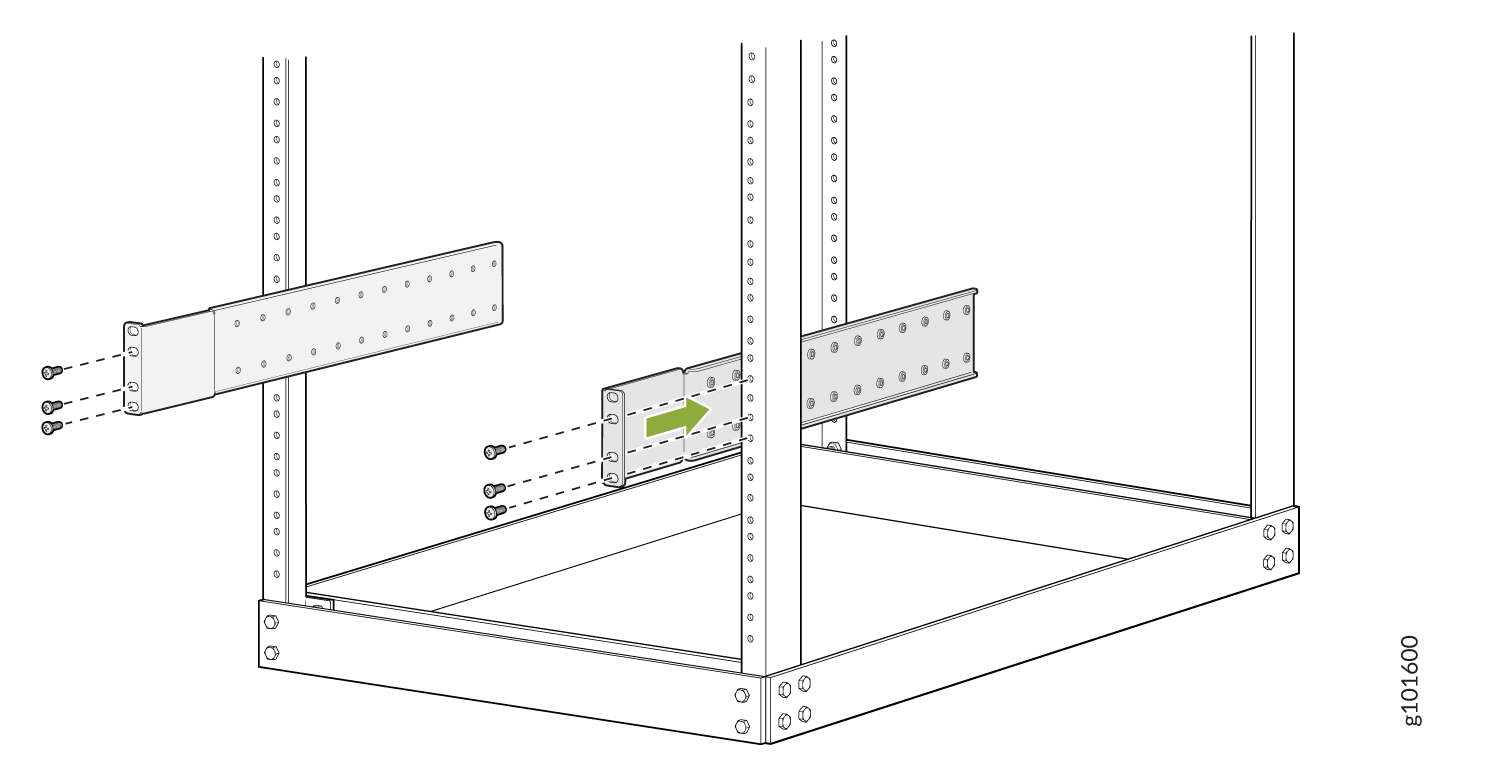
Attach the mounting blades to the front rack posts by using six rack mount screws.
-
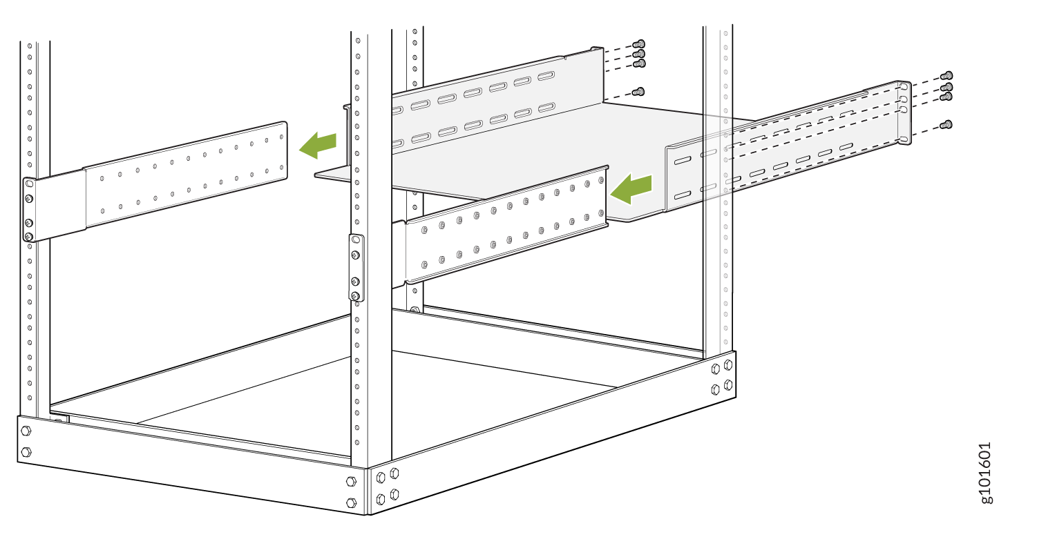
From the rear of the rack, slide the mounting tray into the rear posts of the rack such that the mounting blades slide into the grooves on the mounting tray.
-
Attach the mounting tray to the rear rack posts by using eight rack mount screws.
-
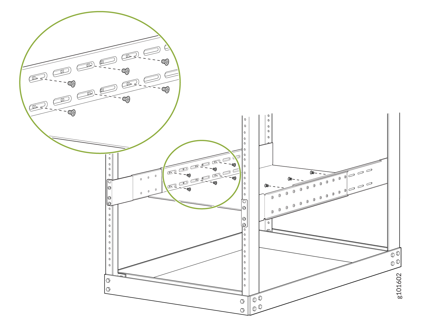
Check that the mounting tray is level.
-
Attach the mounting tray to the mounting blades in the rack with the 12 Phillips 8-32 x .375 in. flat-head screws.
Mount the MX10004 in the Rack and Ground the Chassis
Here’s how to install the MX10004 in a four-post rack:
-
Wrap and fasten one end of the ESD grounding strap around your bare wrist, and connect the other end to a site ESD point.
-
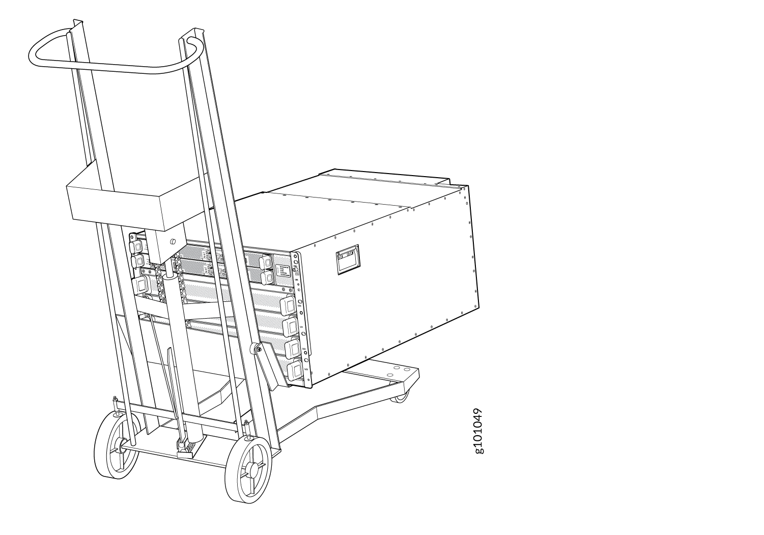
Load the router onto the lift, making sure it rests securely on the lift platform.
-
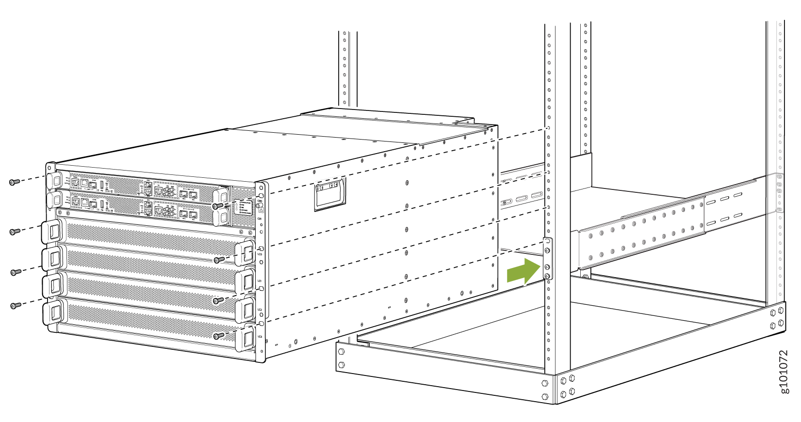
Align the router in front of the rack, centering it in front of the mounting tray.
-
Lift the chassis approximately 0.75 in. (1.9 cm) above the surface of the mounting tray. Align the chassis as close as possible to the mounting tray.
-
Carefully slide the chassis onto the mounting tray until the chassis flanges touch the rack rails.
-
Starting at the bottom, attach the chassis to the rack by inserting eight rack mount screws through each open flange hole and rack hole.
-
Move the lift away from the rack.
-
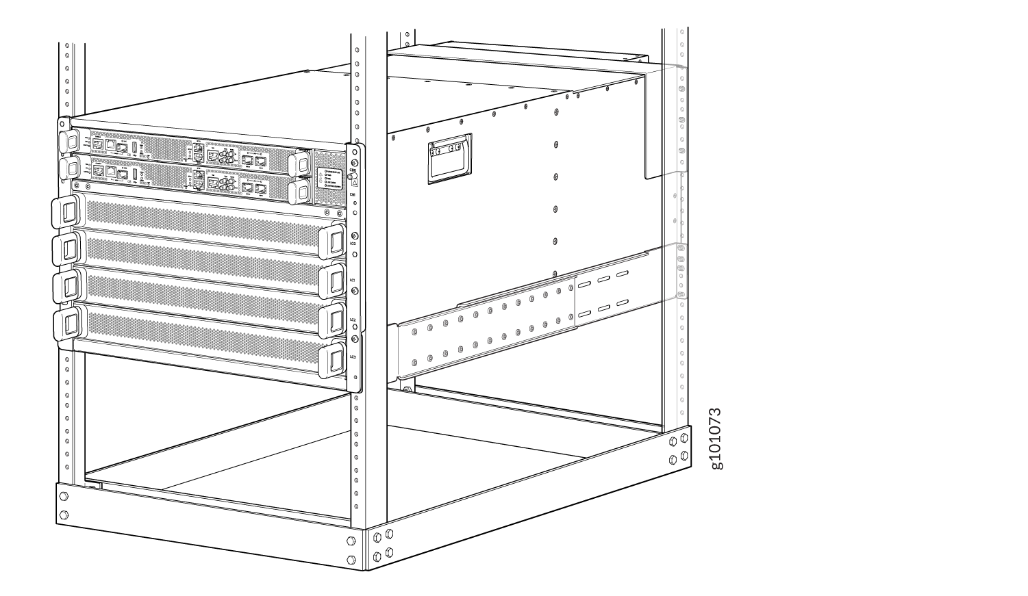
Check the alignment of the router. The rack mount screws on each side of the rack should line up, and the router should be level. Tighten the screws.
-
Insert the safety restraint between the rear posts of the rack. It should rest on the top of the chassis and align with the holes in the rack.
-
Attach the restraint to the rack by inserting six mounting screws through each flange hole and rack hole and tightening the screws.
-
Install the line cards:
-
Remove the line card cover by grasping the handles and pulling straight out to expose the slot for the line card.
Save the cover.
Note:If you are not installing a line card do not remove the line card cover.
-
Slide the line card all the way into the slot until the handle holes line up.
-
Rotate the handles simultaneously into the chassis until the card is fully seated and the handles are vertical.
-
-
Install the optics and optional cable management system.
-
Lift the front door and line up the captive screws in the door with the holes in the chassis flange.
Attach the door to the chassis and rack using the captive screws. Turn the screws until they are finger tight.
-
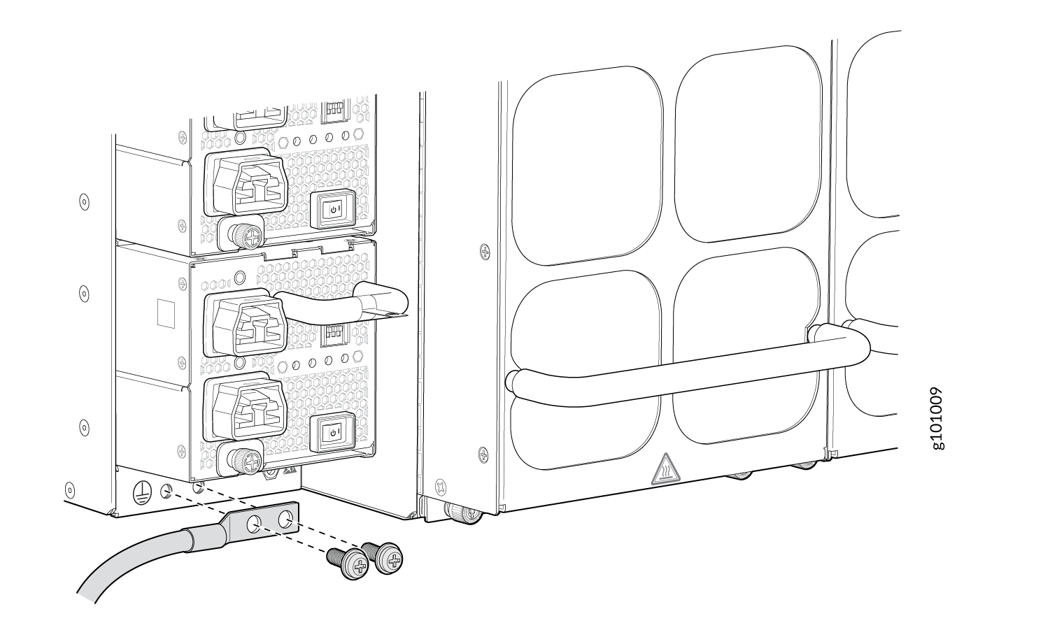
Have a licensed electrician attach the cable lug (provided in the accessory kit) to the grounding cable.
-
Remove the two M6 screws with attached washers below the bottom power supply using a Pozidriv or Phillips screwdriver.
-
Place the chassis grounding lug and cable over the screw holes with the cable connection pointing to the left. Place the two screws with attached washers over the grounding lug and grounding cable. Tighten the two M-6 screws using a Pozidriv or Phillips screwdriver.
Power On
Now that you’ve installed your MX10004 in the rack and grounded the chassis, you’re ready to connect it to power.
The MX10004 supports AC, DC, high-voltage alternating current (HVAC), and high-voltage direct current (HVDC). In this guide, we show you how to connect AC power. For DC, HVAC, and HVDC installations, see MX10004 Universal Routing Platform Hardware Guide.