Creating Unique VPN Routes Using VRF Tables
Understanding Virtual Routing and Forwarding Tables
To separate a VPN’s routes from routes in the public Internet or those in other VPNs, the PE router creates a separate routing table for each VPN, called a VPN routing and forwarding (VRF) table. The PE router creates one VRF table for each VPN that has a connection to a CE router. Any customer or site that belongs to the VPN can access only the routes in the VRF tables for that VPN.
Figure 1 illustrates the VRF tables that are created on the PE routers. The three PE routers have connections to CE routers that are in two different VPNs, so each PE router creates two VRF tables, one for each VPN.
Each VRF table is populated from routes received from directly connected CE sites associated with that VRF routing instance and from routes received from other PE routers that passed BGP community filtering and are in the same VPN.
Each PE router also maintains one global routing table (inet.0) to reach other routers in and outside the provider’s core network.
Each customer connection (that is, each logical interface) is associated with one VRF table. Only the VRF table associated with a customer site is consulted for packets from that site.
You can configure the router so that if a next hop to a destination is not found in the VRF table, the router performs a lookup in the global routing table, which is used for Internet access.
The Junos OS uses the following routing tables for VPNs:
bgp.l3vpn.0—Stores routes learned from other PE routers. Routes in the bgp.l3vpn.0 routing table are copied into a Layer 3 VRF when there is a matching VRF import policy in the PE router. This table is present only on PE routers, and it does not store routes received from directly connected CE routers.
When a PE router receives a route from another PE router, it places the route into its bgp.l3vpn.0 routing table. The route is resolved using the information in the inet.3 routing table. The resultant route is converted into IPv4 format and redistributed to all routing-instance-name.inet.0 routing tables on the PE router if it matches the VRF import policy.
The bgp.l3vpn.0 table is also used to resolve routes over the MPLS tunnels that connect the PE routers. These routes are stored in the inet.3 routing table. PE-to-PE router connectivity must exist in inet.3 (not just in inet.0) for VPN routes to be resolved properly.
When a router is advertising non-local VPN-IPv4 unicast routes and the router is a route reflector or is performing external peering, the VPN-IPv4 unicast routes are automatically exported into the VPN routing table (bgp.l3vpn.0). This enables the router to perform path selection and advertise from the bgp.l3vpn.0 routing table.
To determine whether to add a route to the bgp.l3vpn.0 routing table, the Junos OS checks it against the VRF instance import policies for all the VPNs configured on the PE router. If the VPN-IPv4 route matches one of the policies, it is added to the bgp.l3vpn.0 routing table. To display the routes in the bgp.l3vpn.0 routing table, use the show route table bgp.l3vpn.0 command.
routing-instance-name.inet.0—Stores all unicast IPv4 routes received from directly connected CE routers in a routing instance (that is, in a single VPN) and all explicitly configured static routes in the routing instance. This is the VRF table and is present only on PE routers. For example, for a routing instance named VPN-A, the routing table for that instance is named VPN-A.inet.0.
When a CE router advertises to a PE router, the PE router places the route into the corresponding routing-instance-name.inet.0 routing table and advertises the route to other PE routers if it passes a VRF export policy. Among other things, this policy tags the route with the route distinguisher (route target) that corresponds to the VPN site to which the CE belongs. A label is also allocated and distributed with the route. The bgp.l3vpn.0 routing table is not involved in this process.
The routing-instance-name.inet.0 table also stores routes announced by a remote PE router that match the VRF import policy for that VPN. The PE router redistributed these routes from its bgp.l3vpn.0 table.
Routes are not redistributed from the routing-instance-name.inet.0 table to the bgp.l3vpn.0 table; they are directly advertised to other PE routers.
For each routing-instance-name.inet.0 routing table, one forwarding table is maintained in the router’s Packet Forwarding Engine. This table is maintained in addition to the forwarding tables that correspond to the router’s inet.0 and mpls.0 routing tables. As with the inet.0 and mpls.0 routing tables, the best routes from the routing-instance-name.inet.0 routing table are placed into the forwarding table.
To display the routes in the routing-instance-name.inet.0 table, use the show route table routing-instance-name.inet.0 command.
inet.3—Stores all MPLS routes learned from LDP and RSVP signaling done for VPN traffic. The routing table stores the MPLS routes only if the traffic-engineering bgp-igp option is not enabled.
For VPN routes to be resolved properly, the inet.3 table must contain routes to all the PE routers in the VPN.
To display the routes in the inet.3 table, use the show route table inet.3 command.
inet.0—Stores routes learned by the IBGP sessions between the PE routers. To provide Internet access to the VPN sites, configure the routing-instance-name.inet.0 routing table to contain a default route to the inet.0 routing table.
To display the routes in the inet.0 table, use the show route table inet.0 command.
The following routing policies, which are defined in VRF import and export statements, are specific to VRF tables.
Import policy—Applied to VPN-IPv4 routes learned from another PE router to determine whether the route should be added to the PE router’s bgp.l3vpn.0 routing table. Each routing instance on a PE router has a VRF import policy.
Export policy—Applied to VPN-IPv4 routes that are announced to other PE routers. The VPN-IPv4 routes are IPv4 routes that have been announced by locally connected CE routers.
VPN route processing differs from normal BGP route processing in one way. In BGP, routes are accepted if they are not explicitly rejected by import policy. However, because many more VPN routes are expected, the Junos OS does not accept (and hence store) VPN routes unless the route matches at least one VRF import policy. If no VRF import policy explicitly accepts the route, it is discarded and not even stored in the bgp.l3vpn.0 table. As a result, if a VPN change occurs on a PE router—such as adding a new VRF table or changing a VRF import policy—the PE router sends a BGP route refresh message to the other PE routers (or to the route reflector if this is part of the VPN topology) to retrieve all VPN routes so they can be reevaluated to determine whether they should be kept or discarded.
See Also
Understanding VRF Localization in Layer 3 VPNs
In a Layer 3 VPN, to separate routes of a VPN from routes in the public Internet or those in other VPNs, the PE router creates a separate routing table for each VPN, called a virtual routing and forwarding (VRF) table. Each VRF uses a route distinguisher and route target to differentiate other VPNs so that each VRF achieves a VPN in a public network. The PE router creates one VRF table for each VPN that has a connection to a CE router. Any customer or site that belongs to the VPN can access only the routes in the VRF tables for that VPN.
The PE routers in a Layer 3 VPN deployment have two types of line cards hosting the following interfaces:
CE-facing interfaces
Core-facing interfaces
An FPC can be either core-facing or CE-facing.
The VRFs are present on these line cards and currently, in Junos OS, all the routes of all the VRFs are present on all line cards along with chained composite next hops on all the FPCs. This uses up the memory in each line card. Since traffic from CE-facing interfaces comes in only through the corresponding CE-facing FPCs, all the routes and next hops need not be present on all the line cards. VRF localization provides a mechanism for localizing routes of VRF to specific line cards to help maximize the number of routes that a router can handle. CE-facing interfaces localize all the routes of instance type VRF to a specific line card. If CE-facing interfaces are logical interfaces like AE or RLSQ or IRB, then a line card number has to be configured to localize routes. Core-facing line cards store all the VRF routes. These cards have to be configured as VPN core-facing default or VPN core-facing only. Core-facing line cards store routes of all the VRFs, and they are of the following types:
vpn-core-facing-default — The core-facing FPC installs all the routes and next hops of the VRF routes.
vpn-core-facing-only — The core-facing FPC installs all the routes and does not store next hops of the VRF routes.
Core-facing FPCs can be configured as either core-facing-default or core-facing-only.
Maximizing VPN Routes Using VRF Localization for Layer 3 VPNs
Virtual routing and forwarding (VRF) localization provides
a mechanism for localizing routes of VRF to specific line cards to
help maximize the number of routes that a router can handle. CE-facing
interfaces localize all the routes of instance type VRF to a specific
line card. If the CE-facing interfaces are logical interfaces like
AE/RLSQ/IRB, then the line card has to be configured to localize routes.
Core-facing line cards store all the VRF routes. These cards have
to be configured as VPN core-facing only or VPN core-facing default.
To configure VRF localization, configure the localized-fib statement at the [edit routing-instances instance-name routing-options] hierarchy level and configure the vpn-localization statement at the [edit chassis fpc fpc-slot] hierarchy level. The show route vpn-localization command displays the localization information of all the VRFs in
the system.
Before you begin to localize the VRF table:
Configure the interfaces.
Configure the routing and signaling protocols.
To configure VRF localization:
Example: Improving Scalability Using VRF Localization for Layer 3 VPNs
This example shows how to configure VRF localization on MX Series routers, which enables you to improve the VPN scalability on MX Series routers.
Requirements
This example uses the following hardware and software components:
Five MX Series 5G Universal Routing Platforms
Junos OS Release 14.2 or later running on all devices
Before you begin:
Configure the device interfaces.
Configure the BGP protocol.
Overview
Starting with Junos OS Release 14.2, the VRF localization provides
a mechanism for localizing routes of VRF to specific line cards which
helps maximize the number of routes that a router can handle. CE-facing
interfaces localize all the routes of instance type VRF to a specific
line card. If the CE-facing interfaces are logical interfaces like
AE or RLSQ or IRB, then the line card has to be configured to localize
routes. Core-facing line cards store all the VRF routes. These cards
have to be configured as VPN core-facing only or VPN core-facing default.
To configure VRF localization, configure the localized-fib configuration statement at the [edit routing-instances instance-name routing-options] hierarchy level and
configure vpn-localization at the [edit chassis fpc fpc-slot] hierarchy level. The show route vpn-localization command displays the localization information of all the VRFs in
the system.
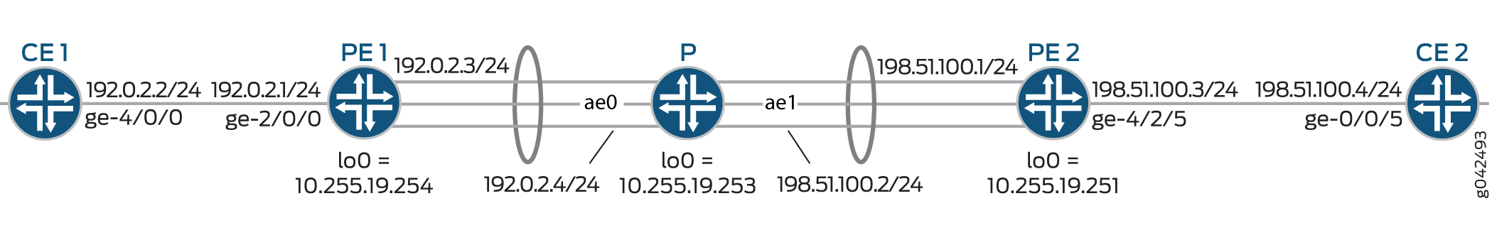
Topology
In the topology shown in Figure 2, VRF localization is configured on Device PE1.
Configuration
CLI Quick Configuration
To quickly configure this example, copy the following commands,
paste them into a text file, remove any line breaks, change any details
necessary to match your network configuration, copy and paste the
commands into the CLI at the [edit] hierarchy level, and
then enter commit from the configuration mode.
CE1
set interfaces ge-4/0/0 unit 0 family inet address 192.0.2.2/24
set interfaces ge-4/0/0 unit 0 family inet6 address abcd:a:a:a:1::2/126
set protocols bgp group vpn1 type external
set protocols bgp group vpn1 export direct
set protocols bgp group vpn1 peer-as 10
set protocols bgp group vpn1 neighbor 192.0.2.1 family inet unicast
set protocols bgp group vpn1 neighbor abcd:a:a:a:1::1 family inet6 unicast
set policy-options policy-statement direct from protocol direct
set policy-options policy-statement direct then accept
set policy-options policy-statement load-balancing-policy then load-balance per-packet
set routing-options autonomous-system 100
set routing-options forwarding-table export load-balancing-policy
PE1
set chassis redundancy graceful-switchover
set chassis aggregated-devices ethernet device-count 16
set chassis fpc 8 vpn-localization vpn-core-facing-only
set chassis network-services enhanced-ip
set interfaces ge-2/0/0 unit 0 family inet address 192.0.2.1/24
set interfaces ge-2/0/0 unit 0 family inet6 address abcd:a:a:a:1::1/126
set interfaces ge-8/1/0 gigether-options 802.3ad ae0
set interfaces ge-8/1/9 gigether-options 802.3ad ae0
set interfaces ae0 unit 0 family inet address 192.0.2.3/24
set interfaces ae0 unit 0 family iso
set interfaces ae0 unit 0 family mpls
set interfaces lo0 unit 1 family inet address 10.255.19.254/24
set interfaces lo0 unit 1 family inet6 address abcd::10:0:1:1/128
set policy-options policy-statement direct from protocol direct
set policy-options policy-statement direct then accept
set policy-options policy-statement load-balancing-policy then load-balance per-packet
set protocols rsvp interface ae0.0
set protocols mpls ipv6-tunneling
set protocols mpls icmp-tunneling
set protocols mpls label-switched-path pe1-pe2-p2mp-1 from 10.255.19.254
set protocols mpls label-switched-path pe1-pe2-p2mp-1 to 10.255.19.251
set protocols mpls label-switched-path pe1-pe2-p2mp-1 link-protection
set protocols mpls label-switched-path pe1-pe2-p2mp-1 p2mp vpn1-p2mp
set protocols mpls label-switched-path pe1-pe3-p2mp-1 from 10.255.19.254
set protocols mpls label-switched-path pe1-pe3-p2mp-1 to 10.255.19.203
set protocols mpls label-switched-path pe1-pe3-p2mp-1 link-protection
set protocols mpls label-switched-path pe1-pe3-p2mp-1 p2mp vpn1-p2mp
set protocols mpls interface ae0.0
set protocols bgp group mpbg type internal
set protocols bgp group mpbg local-address 10.255.19.254
set protocols bgp group mpbg family inet unicast
set protocols bgp group mpbg family inet-vpn unicast
set protocols bgp group mpbg family inet6 unicast
set protocols bgp group mpbg family inet6-vpn unicast
set protocols bgp group mpbg family inet-mvpn signaling
set protocols bgp group mpbg family inet6-mvpn signaling
set protocols bgp group mpbg neighbor 10.255.19.253
set protocols ospf traffic-engineering
set protocols ospf area 0.0.0.0 interface ae0.0
set protocols ospf area 0.0.0.0 interface lo0.0 passive
set protocols ldp interface ae0.0
set routing-instances vpn1 instance-type vrf
set routing-instances vpn1 interface ge-2/0/0.0
set routing-instances vpn1 interface lo0.1
set routing-instances vpn1 route-distinguisher 1:1
set routing-instances vpn1 provider-tunnel rsvp-te static-lsp vpn1-p2mp
set routing-instances vpn1 vrf-target target:1:1
set routing-instances vpn1 vrf-table-label
set routing-instances vpn1 routing-options multipath
set routing-instances vpn1 routing-options localized-fib
set routing-instances vpn1 protocols bgp group grp1 type external
set routing-instances vpn1 protocols bgp group grp1 export direct
set routing-instances vpn1 protocols bgp group grp1 peer-as 100
set routing-instances vpn1 protocols bgp group grp1 neighbor 192.0.2.2 family inet unicast
set routing-instances vpn1 protocols bgp group grp1 neighbor abcd:a:a:a:1::2 family inet6 unicast
set routing-instances vpn1 protocols mvpn
set routing-options nonstop-routing
set routing-options autonomous-system 10
set routing-options forwarding-table export load-balancing-policy
set routing-options forwarding-table chained-composite-next-hop ingress l3vpn extended-space
P
set chassis aggregated-devices ethernet device-count 16
set interfaces ge-1/0/1 gigether-options 802.3ad ae0
set interfaces ge-1/0/3 gigether-options 802.3ad ae0
set interfaces ge-1/1/1 gigether-options 802.3ad ae1
set interfaces ae0 unit 0 family inet address 192.0.2.4/24
set interfaces ae0 unit 0 family iso
set interfaces ae0 unit 0 family mpls
set interfaces ae1 unit 0 family inet address 198.51.100.2/24
set interfaces ae1 unit 0 family iso
set interfaces ae1 unit 0 family mpls
set routing-options autonomous-system 10
set routing-options forwarding-table export load-balancing-policy
set protocols rsvp interface ae0.0
set protocols rsvp interface ae1.0
set protocols mpls ipv6-tunneling
set protocols mpls icmp-tunneling
set protocols mpls interface ae0.0
set protocols mpls interface ae1.0
set protocols bgp group mpbg type internal
set protocols bgp group mpbg local-address 10.255.19.253
set protocols bgp group mpbg family inet unicast
set protocols bgp group mpbg family inet-vpn unicast
set protocols bgp group mpbg family inet6 unicast
set protocols bgp group mpbg family inet6-vpn unicast
set protocols bgp group mpbg family inet-mvpn signaling
set protocols bgp group mpbg family inet6-mvpn signaling
set protocols bgp group mpbg cluster 10.255.19.253
set protocols bgp group mpbg neighbor 10.255.19.254
set protocols bgp group mpbg neighbor 10.255.19.251
set protocols bgp group mpbg neighbor 10.255.19.203
set protocols ospf traffic-engineering
set protocols ospf area 0.0.0.0 interface lo0.0 passive
set protocols ospf area 0.0.0.0 interface ae0.0
set protocols ospf area 0.0.0.0 interface ae1.0
set protocols ldp interface ae0.0
set protocols ldp interface ae1.0
set policy-options policy-statement load-balancing-policy then load-balance per-packet
PE2
set chassis redundancy graceful-switchover
set chassis aggregated-devices ethernet device-count 16
set interfaces ge-4/2/1 gigether-options 802.3ad ae1
set interfaces ge-4/2/5 unit 0 family inet address 198.51.100.3/24
set interfaces ge-4/2/5 unit 0 family inet6 address abcd:a:a:a:2::1/126
set interfaces ae1 unit 0 family inet address 198.51.100.1/24
set interfaces ae1 unit 0 family iso
set interfaces ae1 unit 0 family mpls
set interfaces lo0 unit 2 family inet address 10.255.19.251/24
set interfaces lo0 unit 2 family inet6 address abcd::203:0:113:2/128
set policy-options policy-statement direct from protocol direct
set policy-options policy-statement direct then accept
set policy-options policy-statement load-balancing-policy then load-balance per-packet
set protocols rsvp interface ae1.0
set protocols mpls ipv6-tunneling
set protocols mpls icmp-tunneling
set protocols mpls label-switched-path pe2-pe1-p2mp-1 from 10.255.19.251
set protocols mpls label-switched-path pe2-pe1-p2mp-1 to 10.255.19.254
set protocols mpls label-switched-path pe2-pe1-p2mp-1 link-protection
set protocols mpls label-switched-path pe2-pe1-p2mp-1 p2mp vpn1-p2mp
set protocols mpls label-switched-path pe2-pe3-p2mp-1 from 10.255.19.251
set protocols mpls label-switched-path pe2-pe3-p2mp-1 to 10.255.19.203
set protocols mpls label-switched-path pe2-pe3-p2mp-1 link-protection
set protocols mpls label-switched-path pe2-pe3-p2mp-1 p2mp vpn1-p2mp
set protocols mpls interface ae1.0
set protocols bgp group mpbg type internal
set protocols bgp group mpbg local-address 10.255.19.251
set protocols bgp group mpbg family inet unicast
set protocols bgp group mpbg family inet-vpn unicast per-prefix-label
set protocols bgp group mpbg family inet6 unicast
set protocols bgp group mpbg family inet6-vpn unicast per-prefix-label
set protocols bgp group mpbg family inet-mvpn signaling
set protocols bgp group mpbg family inet6-mvpn signaling
set protocols bgp group mpbg neighbor 10.255.19.253
set protocols ospf traffic-engineering
set protocols ospf area 0.0.0.0 interface lo0.0 passive
set protocols ospf area 0.0.0.0 interface ae1.0
set protocols ldp interface ae1.0
set routing-instances vpn1 instance-type vrf
set routing-instances vpn1 interface ge-4/2/5.0
set routing-instances vpn1 route-distinguisher 1:1
set routing-instances vpn1 provider-tunnel rsvp-te static-lsp vpn1-p2mp
set routing-instances vpn1 vrf-target target:1:1
set routing-instances vpn1 vrf-table-label
set routing-instances vpn1 routing-options multipath
set routing-instances vpn1 protocols bgp group grp1 type external
set routing-instances vpn1 protocols bgp group grp1 export direct
set routing-instances vpn1 protocols bgp group grp1 peer-as 200
set routing-instances vpn1 protocols bgp group grp1 neighbor 198.51.100.4 family inet unicast
set routing-instances vpn1 protocols bgp group grp1 neighbor abcd:a:a:a:2::2 family inet6 unicast
set routing-instances vpn1 protocols mvpn
set routing-options nonstop-routing
set routing-options autonomous-system 10
set routing-options forwarding-table export load-balancing-policy
CE2
set interfaces ge-0/0/5 unit 0 family inet address 198.51.100.4/24
set interfaces ge-0/0/5 unit 0 family inet6 address abcd:a:a:a:2::2/126
set protocols bgp group vpn1 type external
set protocols bgp group vpn1 export direct
set protocols bgp group vpn1 export vpn1
set protocols bgp group vpn1 peer-as 10
set protocols bgp group vpn1 neighbor 198.51.100.3 family inet unicast
set protocols bgp group vpn1 neighbor abcd:a:a:a:2::1 family inet6 unicast
set policy-options policy-statement direct from protocol direct
set policy-options policy-statement direct then accept
set policy-options policy-statement load-balancing-policy then load-balance per-packet
set routing-options autonomous-system 200
set routing-options forwarding-table export load-balancing-policy
Configuring Device PE1
Step-by-Step Procedure
The following example requires you to navigate various levels in the configuration hierarchy. For information about navigating the CLI, see Using the CLI Editor in Configuration Mode.
To configure Device PE1:
Specify the number of aggregated Ethernet interfaces to be created, configure the FPCs as vpn-core-facing-only, and enable enhanced IP network services.
[edit chassis]
user@PE1# set redundancy graceful-switchover
user@PE1# set aggregated-devices ethernet device-count 16
user@PE1# set fpc 8 vpn-localization vpn-core-facing-only
user@PE1# set network-services enhanced-ip
Configure the interfaces.
[edit interfaces]
user@PE1# set ge-2/0/0 unit 0 family inet address 192.0.2.1/24
user@PE1# set ge-2/0/0 unit 0 family inet6 address abcd:a:a:a:1::1/126
user@PE1# set ge-8/1/0 gigether-options 802.3ad ae0
user@PE1# set ge-8/1/9 gigether-options 802.3ad ae0
user@PE1# set ae0 unit 0 family inet address 192.0.2.3/24
user@PE1# set ae0 unit 0 family iso
user@PE1# set ae0 unit 0 family mpls
user@PE1# set lo0 unit 1 family inet address 10.255.19.254/24
user@PE1# set lo0 unit 1 family inet6 address abcd::10:0:1:1/128
Configure policy options to load balance the packets.
[edit policy-options policy-statement]
user@PE1# set direct from protocol direct
user@PE1# set direct then accept
user@PE1# set load-balancing-policy then load-balance per-packet
Configure the RSVP protocol on the interface.
[edit protocols rsvp]
user@PE1# set interface ae0.0
Configure the MPLS protocol.
[edit protocols mpls]
user@PE1# set ipv6-tunneling
user@PE1# set icmp-tunneling
user@PE1# set label-switched-path pe1-pe2-p2mp-1 from 10.255.19.254
user@PE1# set label-switched-path pe1-pe2-p2mp-1 to 10.255.19.251
user@PE1# set label-switched-path pe1-pe2-p2mp-1 link-protection
user@PE1# set label-switched-path pe1-pe2-p2mp-1 p2mp vpn1-p2mp
user@PE1# set label-switched-path pe1-pe3-p2mp-1 from 10.255.19.254
user@PE1# set label-switched-path pe1-pe3-p2mp-1 to 10.255.19.203
user@PE1# set label-switched-path pe1-pe3-p2mp-1 link-protection
user@PE1# set label-switched-path pe1-pe3-p2mp-1 p2mp vpn1-p2mp
user@PE1# set interface ae0.0
Configure the BGP protocol for the mpbg group.
[edit protocols bgp group mpbg]
user@PE1# set type internal
user@PE1# set local-address 10.255.19.254
user@PE1# set family inet unicast
user@PE1# set family inet-vpn unicast
user@PE1# set family inet6 unicast
user@PE1# set family inet6-vpn unicast
user@PE1# set family inet-mvpn signaling
user@PE1# set family inet6-mvpn signaling
user@PE1# set neighbor 10.255.19.253
Configure the OSPF protocol.
[edit protocols ospf]
user@PE1# set traffic-engineering
user@PE1# set area 0.0.0.0 interface ae0.0
user@PE1# set area 0.0.0.0 interface lo0.0 passive
Configure the LDP protocol on the interface.
[edit protocols]
user@PE1# set ldp interface ae0.0
Create an instance type and configure the routing instances on the interface.
[edit routing-instances vpn1]
user@PE1# set instance-type vrf
user@PE1# set interface ge-2/0/0.0
user@PE1# set interface lo0.1
Configure the route distinguisher, and configure the static LSP for the provider tunnel RSVP-TE.
[edit routing-instances vpn1]
user@PE1# set route-distinguisher 1:1
user@PE1# set provider-tunnel rsvp-te static-lsp vpn1-p2mp
Configure the VRF target and the VRF target label for the routing instance.
[edit routing-instances vpn1]
user@PE1# set vrf-target target:1:1
user@PE1# set vrf-table-label
Configure the multipath routing option for a routing instance, and configure the localized fib routing option for the routing instance.
[edit routing-instances vpn1 routing-options]
user@PE1# set multipath
user@PE1# set localized-fib
Configure the group of BGP protocols for a routing instance.
[edit routing-instances vpn1 protocols bgp group grp1]
user@PE1# set type external
user@PE1# set export direct
user@PE1# set peer-as 100
user@PE1# set neighbor 192.0.2.2 family inet unicast
user@PE1# set neighbor abcd:a:a:a:1::2 family inet6 unicast
Configure the MVPN protocols.
[edit routing-instances vpn1]
user@PE1# set protocols mvpn
Configure the nonstop active routing and the autonomous system number for a routing option.
[edit routing-options]
user@PE1# set nonstop-routing
user@PE1# set autonomous-system 10
Configure the load-balancing policy for the forwarding table and extended space for the chained composite next hop for the L3VPN of the forwarding table.
[edit routing-options]
user@PE1# set forwarding-table export load-balancing-policy
user@PE1# set forwarding-table chained-composite-next-hop ingress l3vpn extended-space
Results
From configuration mode, confirm your configuration
by entering the show chassis, show interfaces, show policy-options, show protocols, show routing-instances, and show routing-options commands. If the output does not display the intended configuration,
repeat the instructions in this example to correct the configuration.
user@PE1# show chassis
redundancy {
    graceful-switchover;
}
aggregated-devices {
    ethernet {
        device-count 16;
    }
}
fpc 8 {
    vpn-localization vpn-core-facing-only;
}
network-services enhanced-ip;
user@PE1# show interfaces
ge-2/0/0 {
    unit 0 {
        family inet {
            address 192.0.2.1/24;
        }
        family inet6 {
            address abcd:a:a:a:1::1/126;
        }
    }
}
ge-8/1/0 {
    gigether-options {
        802.3ad ae0;
    }
}
ge-8/1/9 {
    gigether-options {
        802.3ad ae0;
    }
}
ae0 {
    unit 0 {
        family inet {
            address 192.0.2.3/24;
        }
        family iso;
        family mpls;
    }
}
lo0 {
    unit 1 {
        family inet {
            address 10.255.19.254/24;
        }
        family inet6 {
            address abcd::10:0:1:1/128;
        }
    }
}
user@PE1# show policy-options
policy-statement direct {
    from protocol direct;
    then accept;
}
policy-statement load-balancing-policy {
    then {
        load-balance per-packet;
    }
}
user@PE1# show routing-options
nonstop-routing;
autonomous-system 10;
forwarding-table {
    export load-balancing-policy;
    chained-composite-next-hop {
        ingress {
            l3vpn extended-space;
        }
    }
}
user@PE1# show routing-instances
vpn1 {
    instance-type vrf;
    interface ge-2/0/0.0;
    interface lo0.1;
    route-distinguisher 1:1;
    provider-tunnel {
        rsvp-te {
            static-lsp vpn1-p2mp;
        }
    }
    vrf-target target:1:1;
    vrf-table-label;
    routing-options {
        multipath;
        localized-fib;
    }
    protocols {
        bgp {
            group grp1 {
                type external;
                export direct;
                peer-as 100;
                neighbor 192.0.2.2 {
                    family inet {
                        unicast;
                    }
                }
                neighbor abcd:a:a:a:1::2 {
                    family inet6 {
                        unicast;
                    }
                }
            }
        }
        mvpn;
    }
}
user@PE1# show protocols
rsvp {
    interface ae0.0;
}
mpls {
    ipv6-tunneling;
    icmp-tunneling;
    label-switched-path pe1-pe2-p2mp-1 {
        from 10.255.19.254;
        to 10.255.19.251;
        link-protection;
        p2mp vpn1-p2mp;
    }
    label-switched-path pe1-pe3-p2mp-1 {
        from 10.255.19.254;
        to 10.255.19.203;
        link-protection;
        p2mp vpn1-p2mp;
    }
    interface ae0.0;
}
bgp {
    group mpbg {
        type internal;
        local-address 10.255.19.254;
        family inet {
            unicast;
        }
        family inet-vpn {
            unicast;
        }
        family inet6 {
            unicast;
        }
        family inet6-vpn {
            unicast;
        }
        family inet-mvpn {
            signaling;
        }
        family inet6-mvpn {
            signaling;
        }
        neighbor 10.255.19.253;
    }
}
ospf {
    traffic-engineering;
    area 0.0.0.0 {
        interface ae0.0;
        interface lo0.0 {
            passive;
        }
    }
}
ldp {
    interface ae0.0;
}
If you are done configuring the device, enter commit from configuration mode.
Verification
Confirm that the configuration is working properly.
Verifying VRF Localization
Purpose
Verify the localization of VRF in a Layer 3 VPN.
Action
From operational mode, run the show route vpn-localization command for Device PE1.
user@PE1> show route vpn-localization

Routing table: vpn1.inet, Localized
  Index: 7, Address Family: inet, Localization status: Complete
  Local FPC's: 2 8

Routing table: vpn1.inet6, Localized
  Index: 7, Address Family: inet6, Localization status: Complete
  Local FPC's: 2 8

Routing table: vpn2.inet, Non-localized
  Index: 8, Address Family: inet, Localization status: Complete
  Local FPC's: All

Routing table: vpn2.inet6, Non-localized
  Index: 8, Address Family: inet6, Localization status: Complete
  Local FPC's: All
Meaning
The output shows the localization information of all the VRFs.
Verifying VRF Localization for a VPN
Purpose
Verify VRF localization for a VPN.
Action
From operational mode, run the show route vpn-localization
vpn-name vpn-name command.
user@PE1> show route vpn-localization vpn-name vpn1

Routing table: vpn1.inet, Localized
  Index: 7, Address Family: inet, Localization status: Complete
  Local FPC's: 2 8

Routing table: vpn1.inet6, Localized
  Index: 7, Address Family: inet6, Localization status: Complete
  Local FPC's: 2 8
Meaning
The output shows the VPN localization of a VPN.
Filtering Packets in Layer 3 VPNs Based on IP Headers
Including the vrf-table-label statement in the configuration
for a routing instance makes it possible to map the inner label to
a specific VRF routing table; such mapping allows the examination
of the encapsulated IP header at an egress VPN router. You might want
to enable this functionality so that you can do either of the following:
Forward traffic on a PE-router-to-CE-device interface, in a shared medium, where the CE device is a Layer 2 switch without IP capabilities (for example, a metro Ethernet switch).
The first lookup is done on the VPN label to determine which VRF table to refer to, and the second lookup is done on the IP header to determine how to forward packets to the correct end hosts on the shared medium.
Perform egress filtering at the egress PE router.
The first lookup on the VPN label is done to determine which VRF routing table to refer to, and the second lookup is done on the IP header to determine how to filter and forward packets. You can enable this functionality by configuring output filters on the VRF interfaces.
When you include the
vrf-table-labelstatement in the configuration of a VRF routing table, a label-switched interface (LSI) logical interface label is created and mapped to the VRF routing table. Any routes in such a VRF routing table are advertised with the LSI logical interface label allocated for the VRF routing table. When packets for this VPN arrive on a core-facing interface, they are treated as if the enclosed IP packet arrived on the LSI interface and are then forwarded and filtered based on the correct table.
To filter traffic based on the IP header, include the vrf-table-label statement:
vrf-table-label {
    source-class-usage;
}
You can include the statement at the following hierarchy levels:
[edit routing-instances routing-instance-name][edit logical-systems logical-system-name routing-instances routing-instance-name]
You can include the vrf-table-label statement for
both IPv4 and IPv6 Layer 3 VPNs. If you include the statement
for a dual-stack VRF routing table (where both IPv4 and IPv6 routes
are supported), the statement applies to both the IPv4 and IPv6 routes
and the same label is advertised for both sets of routes.
You can also configure SCU accounting for Layer 3 VPNs configured
with the vrf-table-label statement by also including the source-class-usage option. Include the source-class-usage statement at the [edit routing-instances routing-instance-name vrf-table-label] hierarchy level. The source-class-usage statement at this hierarchy level is supported only for the vrf instance type (Layer 3 VPNs). DCU is not supported for
the vrf-table-label statement. For more information, see Enabling Source Class and Destination Class Usage.
The following sections provide more information about traffic filtering based on the IP header:
- Egress Filtering Options
- Support on Aggregated and VLAN Interfaces for IP-Based Filtering
- Support on ATM and Frame Relay Interfaces for IP-Based Filtering
- Support on Ethernet, SONET/SDH, and T1/T3/E3 Interfaces for IP-Based Filtering
- Support on SONET/SDH and DS3/E3 Channelized Enhanced Intelligent Queuing Interfaces for IP-Based Filtering
- Support on Multilink PPP and Multilink Frame Relay Interfaces for IP-Based Filtering
- Support for IP-Based Filtering of Packets with Null Top Labels
- General Limitations on IP-Based Filtering
Egress Filtering Options
You can enable egress filtering (which allows egress Layer 3
VPN PE routers to perform lookups on the VPN label and IP header
at the same time) by including the vrf-table-label statement
at the [edit routing-instances instance-name] hierarchy level. There is no restriction on including this
statement for CE-router-to-PE-router interfaces, but there are several
limitations on other interface types, as described in subsequent sections
in this topic.
You can also enable egress filtering by configuring a VPN tunnel (VT) interface on routing platforms equipped with a Tunnel Services Physical Interface Card (PIC). When you enable egress filtering this way, there is no restriction on the type of core-facing interface used. There is also no restriction on the type of CE-router-to-PE-router interface used.
Support on Aggregated and VLAN Interfaces for IP-Based Filtering
Support for the vrf-table-label statement over aggregated
and VLAN interfaces is available on the routers summarized in Table 1.
Interfaces |
M Series Router Without an Enhanced FPC |
M Series Router with an Enhanced FPC |
M320 Router |
T Series Router |
|---|---|---|---|---|
Aggregated |
No |
Yes |
Yes |
Yes |
VLAN |
No |
Yes |
Yes |
Yes |
The vrf-table-label statement is not supported for
Aggregated Gigabit Ethernet, 10-Gigabit Ethernet, and VLAN physical
interfaces on M120 routers.
Support on ATM and Frame Relay Interfaces for IP-Based Filtering
Support for the vrf-table-label statement
over Asynchronous Transfer Mode (ATM) and Frame Relay interfaces is
available on the routers summarized in Table 2.
Interfaces |
M Series Router Without an Enhanced FPC |
M Series Router with an Enhanced FPC |
M320 Router |
T Series Router |
|---|---|---|---|---|
ATM1 |
No |
No |
No |
No |
ATM2 intelligent queuing (IQ) |
No |
Yes |
Yes |
Yes |
Frame Relay |
No |
Yes |
Yes |
Yes |
Channelized |
No |
No |
No |
No |
When you include the vrf-table-label statement, be aware of the following limitations with ATM or Frame
Relay interfaces:
The
vrf-table-labelstatement is supported on ATM interfaces, but with the following limitations:ATM interfaces can be configured on the M320 router and the T Series routers, and on M Series routers with an enhanced FPC.
The interface can only be a PE router interface receiving traffic from a P router.
The router must have an ATM2 IQ PIC.
The
vrf-table-labelstatement is also supported on Frame Relay encapsulated interfaces, but with the following limitations:Frame Relay interfaces can be configured on the M320 router and the T Series routers, and on M Series routers with an enhanced FPC.
The interface can only be a PE router interface receiving traffic from a P router.
Support on Ethernet, SONET/SDH, and T1/T3/E3 Interfaces for IP-Based Filtering
Support for the vrf-table-label statement
over Ethernet, SONET/SDH, and T1/T3/E3 interfaces is available on
the routers summarized in Table 3.
Interfaces |
M Series Router Without an Enhanced FPC |
M Series Router with an Enhanced FPC |
M320 Router |
T Series Router |
|---|---|---|---|---|
Ethernet |
Yes |
Yes |
Yes |
Yes |
SONET/SDH |
Yes |
Yes |
Yes |
Yes |
T1/T3/E3 |
Yes |
Yes |
Yes |
Yes |
Only the following Ethernet PICs support the vrf-table-label statement on M Series routers without an Enhanced FPC:
1-port Gigabit Ethernet
2-port Gigabit Ethernet
4-port Fast Ethernet
Support on SONET/SDH and DS3/E3 Channelized Enhanced Intelligent Queuing Interfaces for IP-Based Filtering
Support for the vrf-table-label statement for the
specified channelized IQE interfaces is only available on M120 and
M320 routers with Enhanced III FPCs as summarized in Table 4.
Interfaces |
M120 Routers with Enhanced III FPCs |
M320 Routers with Enhanced III FPCs |
|---|---|---|
OC12 |
Yes |
Yes |
STM4 |
Yes |
Yes |
OC3 |
Yes |
Yes |
STM1 |
Yes |
Yes |
DS3 |
Yes |
Yes |
E3 |
Yes |
Yes |
The following IQE Type-1 PICs are supported:
1-port OC12/STM4 IQE with SFP
4-port OC3/STM1 IQE with SFP
4-port DS3/E3 IQE with BNC
2-port Channelized OC3/STM1 IQE with SFP, with no SONET partitions
1-port Channelized OC12/STM4 IQE with SFP, with no SONET partitions
The following constraints are applicable with respect to a router configuration utilizing logical systems:
Multiport IQE PIC interfaces constraints—On multiport IQE PICs, such as the 2-port Channelized OC3/STM1 IQE with SFP, if the port 1 interface is configured as one logical system with its own routing-instance and the port 2 interface is configured as a different logical system with its own routing instances such that there are core-facing logical interfaces on both port 1 and port 2, then you cannot configure the
vrf-table-labelstatement on routing-instance in both logical systems. Only one set of LSI labels are supported; the last routing instance with thevrf-table-labelstatement configured is committed.Frame Relay encapsulation and logical interfaces across logical systems constraints—Similar to the multiport PIC with logical systems, if you try to configure one logical interface of an IQE PIC with Frame Relay encapsulation in one logical system and configure another logical interface on the same IQE PIC in the second logical system, the configuration will not work for all the
vrf-table-labelstatement configured instances. It will only work for the instances configured in one of the logical systems.
Both the above constraints occur because the router configuration
maintains one LSI tree in the Packet Forwarding Engine per logical
system, which is common across all streams. The stream channel table
lookup is then adjusted to point to the LSI tree. In the case of multiport
type-1 IQE PICs, all physical interfaces share the same stream. Therefore,
the logical interfaces (multiport or not) obviously share the same
stream. Consequently, the LSI binding is at the stream level. Hence,
provisioning logical interfaces under the same stream provisioned
to be core-facing and supporting a different set of routing instances
with the vrf-table-label statement is not supported.
Support on Multilink PPP and Multilink Frame Relay Interfaces for IP-Based Filtering
Support for the vrf-table-label statement
over Multilink Point-to-Point Protocol (MLPPP) and Multilink Frame
Relay (MLFR) interfaces is available on the routers summarized in Table 5.
Interfaces |
M Series Router Without an Enhanced FPC |
M Series Router with an Enhanced FPC |
M320 |
T Series Router |
MX Series Router |
|---|---|---|---|---|---|
MLPPP |
No |
Yes |
No |
No |
No |
End-to-End MLFR (FRF.15) |
No |
Yes |
No |
No |
No |
UNI/NNI MLFR (FRF.16) |
No |
No |
No |
No |
No |
M Series routers must have an AS PIC to support the vrf-table-label statement over MLPPP and MLFR interfaces. The vrf-table-label statement over MLPPP interfaces is not supported on M120 routers.
Support for IP-Based Filtering of Packets with Null Top Labels
You can include the vrf-table-label statement in
the configuration for core-facing interfaces receiving MPLS packets
with a null top label, which might be transmitted by some vendors’
equipment. These packets can be received only on the M320 router,
the M10i router, and T Series Core routers using one of the following
PICs:
1-port Gigabit Ethernet with SFP
2-port Gigabit Ethernet with SFP
4-port Gigabit Ethernet with SFP
10-port Gigabit Ethernet with SFP
1-port SONET STM4
4-port SONET STM4
1-port SONET STM16
1-port SONET STM16 (non-SFP)
4-port SONET STM16
1-port SONET STM64
The following PICs can receive packets with null top labels, but only when installed in an M120 router or an M320 router with an Enhanced III FPC:
1-port 10-Gigabit Ethernet
1-port 10-Gigabit Ethernet IQ2
General Limitations on IP-Based Filtering
The following limitations apply when you include the vrf-table-label statement:
Firewall filters cannot be applied to interfaces included in a routing instance on which you have configured the
vrf-table-labelstatement.The time-to-live (TTL) value in the MPLS header is not copied back to the IP header of packets sent from the PE router to the CE router.
You cannot include the
vrf-table-labelstatement in a routing instance configuration that also includes a virtual loopback tunnel interface; the commit operation fails in this case.When you include the statement, MPLS packets with label-switched interface (LSI) labels that arrive on core-facing interfaces are not counted at the logical interface level if the core-facing interface is any of the following:
ATM
Frame Relay
Ethernet configured with VLANs
Aggregated Ethernet configured with VLANs
For LMNR, Stoli, and I-Chip-based Packet Forwarding Engines, you cannot include the statement in the configuration of a VRF routing instance if the PE-router-to-P-router interface is any of the following interfaces:
Note:The
vrf-table-labelstatement is supported when the PE-router-to-P-router interface is a tunnel interface on a Junos Trio-based Packet Forwarding Engine, so no limitation applies.Aggregated SONET/SDH interface
Channelized interface
Tunnel interface (for example, generic routing encapsulation [GRE] or IP Security [IPsec])
Circuit cross-connect (CCC) or translational cross-connect (TCC) encapsulated interface
Logical tunnel interface
Virtual private LAN service (VPLS) encapsulated interface
Note:All CE-router-to-PE-router and PE-router-to-CE-router interfaces are supported.
You cannot include the
vrf-table-labelstatement in the configuration of a VRF routing instance if the PE-router-to-P-router PIC is one of the following PICs:10-port E1
8-port Fast Ethernet
12-port Fast Ethernet
48-port Fast Ethernet
ATM PIC other than the ATM2 IQ
Label-switched interface (LSI) traffic statistics are not supported for Intelligent Queuing 2 (IQ2), Enhanced IQ (IQE), and Enhanced IQ2 (IQ2E) PICs on M Series routers.
See Also
Configuring a Label Allocation and Substitution Policy for VPNs
You can control label-advertisements on MPLS ingress and AS border routers (ASBRs). Labels can be assigned on a per–next-hop (by default) or on a per-table basis (by configuring the vrf-table-label statement). This choice affects all routes of a given routing instance. You can also configure a policy to generate labels on a per-route basis by specifying a label allocation policy.
To specify a label allocation policy for the routing
instance, configure the label statement and specify a label
allocation policy using the allocation option:
label {
    allocation label-allocation-policy;
}
You can configure this statement at the following hierarchy levels:
[edit routing-instances routing-instance-name routing-options][edit logical-systems logical-system-name routing-instances routing-instance-name routing-options]
The [edit logical-systems] hierarchy level
is not applicable in ACX Series routers.
To configure the label allocation policy, include the label-allocation statement at the [edit policy-options policy-statement policy-statement-name term term-name then] hierarchy level. You can configure the label allocation
mode as either per-nexthop or per-table.
For a VPN option B ASBR, labels for transit routes are substituted for a local virtual tunnel label or vrf-table-label label. When a VRF table is configured on the ASBR (this type of configuration is uncommon for the option B model), the ASBR does not generate MPLS swap or swap and push state for transit routes. Instead, the ASBR re-advertises a local virtual-tunnel or vrf-table-label label and forwards that transit traffic based on IP forwarding tables. The label substitution helps to conserve labels on Juniper Networks routers.
However, this type of label substitution effectively breaks the MPLS forwarding path, which becomes visible when using an MPLS OAM command such as LSP ping. You can configure the way in which labels are substituted on a per-route basis by specifying a label substitution policy.
To specify a label substitution policy for the routing
instance, configure the label statement and specify a label
substitution policy using the substitution option:
label {
    substitution label-substitution-policy;
}
You can configure this statement at the following hierarchy levels:
[edit routing-instances routing-instance-name routing-options][edit logical-systems logical-system-name routing-instances routing-instance-name routing-options]
The [edit logical-systems] hierarchy level
is not applicable in ACX Series routers.
The label substitution policy is used to determine whether or
not a label should be substituted on an ASBR router. The results of
the policy operation are either accept (label substitution
is performed) or reject (label substitution is not performed).
The default behavior is accept. The following set command
example illustrates how you can configure a reject label
substitution policy: set policy-options policy-statement no-label-substitution
term default then reject.