Egress Protection in Layer 3 VPNs
This topic introduces the concept and components in egress protection in layer 3 VPN. It describes and provides examples on how to configure the protected, protector, and point of local repair (PLR) routers.
Egress Protection for BGP Labeled Unicast
When network node or link failures occur, it takes some time to restore service using traditional routing table convergence. Local repair procedures can provide much faster restoration by establishing local protection as close to a failure as possible. Fast protection for egress nodes is available to services in which BGP labeled unicast interconnects IGP areas, levels, or autonomous systems (ASs). If a provider router detects that an egress router (AS or area border router) is down, it immediately forwards the traffic destined to that router to a protector router that forwards the traffic downstream to the destination.
To provide egress protection for BGP labeled unicast, the protector node must create a backup state for downstream destinations before the failure happens. The basic idea of the solution is that the protector node constructs a forwarding state associated with the protected node and relays the MPLS labels assigned by the protected node further downstream to the final destination.
This feature supports the applications Inter-AS Option C and Seamless MPLS.
Inter-AS Option C—BGP labeled unicast provides end-to-end transport label-switched paths (LSPs) by stitching the intra-AS LSPs together. AS boundary routers run EBGP to other AS boundary routers to exchange labels for /32 PE loopback routes. IBGP runs between the provider edge router and AS boundary routers within each AS. In Figure 1, the traffic goes from CE1 to CE2. ASBR1 is the protected AS boundary router, ASBR2 is the protector, and Device P1 is the point of local repair (PLR). The primary path is chosen from PE1 to PE2 over ASBR1 and ASBR3. When ASBR1 fails, Router P1 detects the ASBR1 failure and forwards the traffic to ASBR2, which provides backup service and forwards the traffic downstream.
Seamless MPLS—BGP labeled unicast provides end-to-end transport LSPs by stitching the intra-area/level LSPs. Area border routers (ABRs) run BGP labeled unicast to other ABRs to exchange labels for /32 PE loopback routes. In Figure 2, the traffic goes from Device CE1 to Device CE2. ABR1 is the protected ABR, ABR2 is the protector, and T1 is the PLR. The primary path is chosen from PE1 to PE2 over ABR1 and ABR3. When ABR1 fails, Router T1 detects the ABR1 failure and forwards the traffic to ABR2, which provides backup service and forwards the traffic downstream.
In each of these applications, the protected node advertises a primary BGP labeled unicast route that needs protection. When fast protection is enabled, BGP advertises the label routes with a special address as the next hop. This special address is a context identifier that is configured through the CLI. The protected node also advertises the context identifier in IGP and a NULL label in LDP for the context identifier.
The backup node advertises backup BGP labeled unicast routes for the protected routes. The protector node forwards traffic to the backup node using the labels advertised by the backup node.
The protector node provides the backup service by cross-connecting the labels originated by the protected node and the labels originated by the backup node. The protector node forwards the traffic to the backup node in case of failure of the protected node. The protector node advertises the same context-identifier into IGP with high metric. Also, it advertises a real label in LDP for the context identifier. The protector node listens for the BGP labeled unicast routes advertised by both the protected node and backup node and populates the context label table and backup FIB. When traffic with the real context LDP label arrives, the lookup is done in the context of a protected node. The protector node often acts as the backup node.
The PLR detects the protected node failure and forwards the MPLS traffic to the protector node. The high IGP metric along with the LDP label advertised by the protector node ensure that the PLR uses the protector node as an LDP backup LSP.
There are two supported protection types: collocated protector and centralized protector. In the collocated type, the protector node is also the backup node. In the centralized type, the backup node is different from the protector node.
Configuring Egress Protection for BGP Labeled Unicast
Fast protection for egress nodes is available to services in which BGP labeled unicast interconnects IGP areas, levels, or ASs. If a provider router detects that an egress router (AS or area border router) is down, it immediately forwards the traffic destined to that router to a protector router that forwards the traffic downstream to the destination.
Before configuring egress protection for BGP labeled unicast, ensure that all routers in the AS or area are running Junos OS 14.1 or a later release.
To configure egress protection for BGP labeled unicast:
See Also
Example: Configuring Egress Protection for BGP Labeled Unicast
This example shows how to configure BGP labeled unicast protection that can be used in case of a PE failure in an Inter-AS Option C topology.
Requirements
This example uses the following hardware and software components:
M Series Multiservice Edge Routers, MX Series 5G Universal Routing Platforms, or T Series Core Routers
Junos OS Release 14.1 or later
Overview
When network node or link failures occur, it takes some time to restore service using traditional routing table convergence. Local repair procedures can provide much faster restoration by establishing local protection as close to a failure as possible. Fast protection for egress nodes is available to services in which BGP labeled unicast interconnects IGP areas, levels, or autonomous systems (ASs). If a provider router detects that an egress router (AS or area border router) is down, it immediately forwards the traffic destined to that router to a protector router that forwards the traffic downstream to the destination.
This example shows how to configure labeled-unicast egress protection in a Layer 3 VPN.
Topology
In this example, an Inter-AS Option C topology is set up by configuring two customer edge (CE) devices and six service provider edge (PE) devices in four autonomous systems. The CE devices are configured in AS100 and AS101. The PE devices are configured in AS200 and AS300.
Figure 3 shows the topology used in this example.
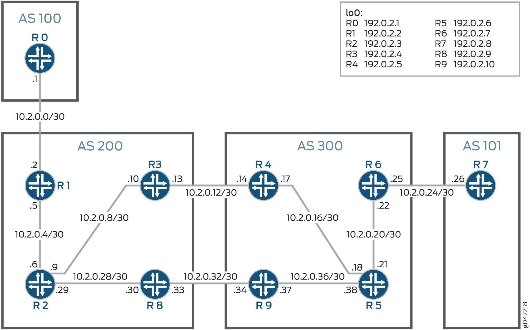
The aim of this example is to protect PE Router R4. Egress protection is configured on Router R4 and Router R9 so that the traffic can be routed through the backup link (R9 to R8) when Router R4 (or the link from R5 to R4) goes down. In this example, Router R4 is the protected router, Router R9 is the protector router, and Router R5 is the point of local repair (PLR).
Configuration
CLI Quick Configuration
To quickly configure this example, copy the
following commands, paste them into a text file, remove any line breaks,
change any details necessary to match your network configuration,
and then copy and paste the commands into the CLI at the [edit] hierarchy level.
Router R0
set interfaces ge-0/0/0 unit 0 description toR1
set interfaces ge-0/0/0 unit 0 family inet address 10.2.0.1/30
set interfaces lo0 unit 0 family inet address 192.0.2.1/24 primary
set routing-options router-id 192.0.2.1
set routing-options autonomous-system 100
set protocols ospf area 0.0.0.0 interface lo0.0 passive
set protocols ospf area 0.0.0.0 interface ge-0/0/0.0 metric 10
Router R1
set interfaces ge-0/0/0 unit 0 description toR0
set interfaces ge-0/0/0 unit 0 family inet address 10.2.0.2/30
set interfaces ge-0/0/0 unit 0 family mpls
set interfaces ge-0/0/1 unit 0 description toR2
set interfaces ge-0/0/1 unit 0 family inet address 10.2.0.5/30
set interfaces ge-0/0/1 unit 0 family mpls
set interfaces lo0 unit 0 family inet address 192.0.2.2/24
set routing-options router-id 192.0.2.2
set routing-options autonomous-system 200
set protocols mpls label-switched-path ToR3 to 192.0.2.4
set protocols mpls label-switched-path ToR8 to 192.0.2.9
set protocols mpls interface all
set protocols bgp group parent-vpn-peers type internal
set protocols bgp group parent-vpn-peers local-address 192.0.2.2
set protocols bgp group parent-vpn-peers family inet unicast
set protocols bgp group parent-vpn-peers family inet labeled-unicast rib inet.3
set protocols bgp group parent-vpn-peers neighbor 192.0.2.4
set protocols bgp group parent-vpn-peers neighbor 192.0.2.9
set protocols bgp group toR6 type external
set protocols bgp group toR6 multihop ttl 10
set protocols bgp group toR6 local-address 192.0.2.2
set protocols bgp group toR6 family inet-vpn unicast
set protocols bgp group toR6 peer-as 300
set protocols bgp group toR6 neighbor 192.0.2.7
set protocols ospf traffic-engineering
set protocols ospf area 0.0.0.0 interface lo0.0 passive
set protocols ospf area 0.0.0.0 interface ge-0/0/1.0 metric 10
set protocols ldp interface ge-0/0/1.0
set protocols ldp interface lo0.0
set policy-options policy-statement child_vpn_routes term 1 from protocol bgp
set policy-options policy-statement child_vpn_routes term 1 then accept
set policy-options policy-statement child_vpn_routes term 2 then reject
set policy-options policy-statement vpnexport term 1 from protocol ospf
set policy-options policy-statement vpnexport term 1 then community add test_comm
set policy-options policy-statement vpnexport term 1 then accept
set policy-options policy-statement vpnexport term 2 then reject
set policy-options policy-statement vpnimport term 1 from protocol bgp
set policy-options policy-statement vpnimport term 1 from community test_comm
set policy-options policy-statement vpnimport term 1 then accept
set policy-options policy-statement vpnimport term 2 then reject
set policy-options community text_comm members target:1:200
set routing-instances customer-provider-vpn instance-type vrf
set routing-instances customer-provider-vpn interface ge-0/0/0.0
set routing-instances customer-provider-vpn route-distinguisher 192.0.2.4:1
set routing-instances customer-provider-vpn vrf-import vpnimport
set routing-instances customer-provider-vpn vrf-export vpnexport
set routing-instances customer-provider-vpn vrf-target target:200:1
set routing-instances customer-provider-vpn protocols ospf export child_vpn_routes
set routing-instances customer-provider-vpn protocols ospf area 0.0.0.0 interface ge-0/0/0.0
Router R2
set interfaces ge-0/0/0 unit 0 description toR3
set interfaces ge-0/0/0 unit 0 family inet address 10.2.0.9/30
set interfaces ge-0/0/0 unit 0 family mpls
set interfaces ge-0/0/1 unit 0 description toR1
set interfaces ge-0/0/1 unit 0 family inet address 10.2.0.6/30
set interfaces ge-0/0/1 unit 0 family mpls
set interfaces ge-0/0/2 unit 0 description toR8
set interfaces ge-0/0/2 unit 0 family inet address 10.2.0.29/30
set interfaces ge-0/0/2 unit 0 family mpls
set interfaces lo0 unit 0 family inet address 192.0.2.3/24
set routing-options router-id 192.0.2.3
set routing-options autonomous-system 200
set protocols mpls interface all
set protocols ospf traffic-engineering
set protocols ospf area 0.0.0.0 interface lo0.0 passive
set protocols ospf area 0.0.0.0 interface ge-0/0/0.0 metric 10
set protocols ospf area 0.0.0.0 interface ge-0/0/1.0 metric 10
set protocols ospf area 0.0.0.0 interface ge-0/0/2.0 metric 10
set protocols ldp interface ge-0/0/0.0
set protocols ldp interface ge-0/0/1.0
set protocols ldp interface ge-0/0/2.0
set protocols ldp interface lo0.0
Router R3
set interfaces ge-0/0/0 unit 0 description toR2
set interfaces ge-0/0/0 unit 0 family inet address 10.2.0.10/30
set interfaces ge-0/0/0 unit 0 family mpls
set interfaces ge-0/0/1 unit 0 description toR4
set interfaces ge-0/0/1 unit 0 family inet address 10.2.0.13/30
set interfaces ge-0/0/1 unit 0 family mpls
set interfaces lo0 unit 0 family inet address 192.0.2.4/24
set routing-options router-id 192.0.2.4
set routing-options autonomous-system 200
set protocols mpls traffic-engineering bgp-igp-both-ribs
set protocols mpls label-switched-path ToR1 to 192.0.2.2
set protocols mpls interface all
set protocols bgp group toR4 type external
set protocols bgp group toR4 family inet unicast
set protocols bgp group toR4 family inet labeled-unicast rib inet.3
set protocols bgp group toR4 export send-pe
set protocols bgp group toR4 neighbor 10.2.0.14 peer-as 300
set protocols bgp group parent-vpn-peers type internal
set protocols bgp group parent-vpn-peers local-address 192.0.2.4
set protocols bgp group parent-vpn-peers family inet unicast
set protocols bgp group parent-vpn-peers family inet labeled-unicast rib inet.3
set protocols bgp group parent-vpn-peers export next-hop-self
set protocols bgp group parent-vpn-peers neighbor 192.0.2.2
set protocols bgp group parent-vpn-peers neighbor 192.0.2.9
set protocols ospf traffic-engineering
set protocols ospf export from-bgp
set protocols ospf area 0.0.0.0 interface lo0.0 passive
set protocols ospf area 0.0.0.0 interface ge-0/0/0.0 metric 10
set protocols ldp interface ge-0/0/0.0
set protocols ldp interface ge-0/0/1.0
set protocols ldp interface lo0.0
set policy-options policy-statement next-hop-self term 1 then next-hop-self
set policy-options policy-statement send-pe from route-filter 192.0.2.2/24 exact
set policy-options policy-statement send-pe then accept
Router R4
set interfaces ge-0/0/0 unit 0 description toR5
set interfaces ge-0/0/0 unit 0 family inet address 10.2.0.17/30
set interfaces ge-0/0/0 unit 0 family iso
set interfaces ge-0/0/0 unit 0 family mpls
set interfaces ge-0/0/1 unit 0 description toR3
set interfaces ge-0/0/1 unit 0 family inet address 10.2.0.14/30
set interfaces ge-0/0/1 unit 0 family mpls
set interfaces lo0 unit 0 family inet address 192.0.2.5/24
set interfaces lo0 unit 0 family iso address 47.0005.80ff.f800.0000.0108.0001.0102.5507.2049.00
set routing-options router-id 192.0.2.5
set routing-options autonomous-system 300
set protocols mpls traffic-engineering bgp-igp-both-ribs
set protocols mpls label-switched-path ToR6 to 192.0.2.7
set protocols mpls interface all
set protocols mpls interface fxp.0 disable
set protocols mpls egress-protection context-identifier 203.0.113.1 primary
set protocols bgp group parent-vpn-peers type internal
set protocols bgp group parent-vpn-peers local-address 192.0.2.5
set protocols bgp group parent-vpn-peers family inet unicast
set protocols bgp group parent-vpn-peers family inet labeled-unicast rib inet.3
set protocols bgp group parent-vpn-peers family inet labeled-unicast egress-protection context-identifier 203.0.113.1
set protocols bgp group parent-vpn-peers export next-hop-self
set protocols bgp group parent-vpn-peers neighbor 192.0.2.7
set protocols bgp group parent-vpn-peers neighbor 192.0.2.10
set protocols bgp group toR3 type external
set protocols bgp group toR3 family inet labeled-unicast rib inet.3
set protocols bgp group toR3 export send-pe
set protocols bgp group toR3 peer-as 200
set protocols bgp group toR3 neighbor 10.2.0.13
set protocols isis level 1 disable
set protocols isis level 2 wide-metrics-only
set protocols isis interface ge-0/0/0.0 level 2 metric 10
set protocols isis interface lo0.0 passive
set protocols ldp interface ge-0/0/0.0
set protocols ldp interface ge-0/0/1.0
set protocols ldp interface lo0.0
set policy-options policy-statement next-hop-self term 1 then next-hop-self
set policy-options policy-statement send-pe from route-filter 192.0.2.7/24 exact
set policy-options policy-statement send-pe then accept
Router R5
set interfaces ge-0/0/0 unit 0 description toR4
set interfaces ge-0/0/0 unit 0 family inet address 10.2.0.18/30
set interfaces ge-0/0/0 unit 0 family iso
set interfaces ge-0/0/0 unit 0 family mpls
set interfaces ge-0/0/1 unit 0 description toR6
set interfaces ge-0/0/1 unit 0 family inet address 10.2.0.21/30
set interfaces ge-0/0/1 unit 0 family iso
set interfaces ge-0/0/1 unit 0 family mpls
set interfaces ge-0/0/2 unit 0 description toR9
set interfaces ge-0/0/2 unit 0 family inet address 10.2.0.38/30
set interfaces ge-0/0/2 unit 0 family iso
set interfaces ge-0/0/2 unit 0 family mpls
set interfaces lo0 unit 0 family inet address 192.0.2.6/24
set interfaces lo0 unit 0 family iso address 47.0005.80ff.f800.0000.0108.0001.0102.5507.2050.00
set routing-options router-id 192.0.2.6
set routing-options autonomous-system 300
set protocols mpls interface all
set protocols mpls interface fxp0.0 disable
set protocols isis backup-spf-options per-prefix-calculation
set protocols isis level 1 disable
set protocols isis level 2 wide-metrics-only
set protocols isis interface all node-link-protection
set protocols isis interface fxp0.0 disable
set protocols isis interface ge-0/0/0.0 link-protection
set protocols isis interface ge-0/0/0.0 level 2 metric 10
set protocols isis interface ge-0/0/1.0 link-protection
set protocols isis interface ge-0/0/1.0 level 2 metric 10
set protocols isis interface ge-0/0/2.0 link-protection
set protocols isis interface ge-0/0/2.0 level 2 metric 10
set protocols isis interface lo0.0 passive
set protocols ldp track-igp-metric
set protocols ldp interface all
set protocols ldp interface fxp0.0 disable
Router R6
set interfaces ge-0/0/0 unit 0 description toR7
set interfaces ge-0/0/0 unit 0 family inet address 10.2.0.25/30
set interfaces ge-0/0/0 unit 0 family iso
set interfaces ge-0/0/0 unit 0 family mpls
set interfaces ge-0/0/1 unit 0 description toR5
set interfaces ge-0/0/1 unit 0 family inet address 10.2.0.22/30
set interfaces ge-0/0/1 unit 0 family iso
set interfaces ge-0/0/1 unit 0 family mpls
set interfaces lo0 unit 0 family inet address 192.0.2.7/24
set interfaces lo0 unit 0 family iso address 47.0005.80ff.f800.0000.0108.0001.0102.5507.2048.00
set routing-options router-id 192.0.2.7
set routing-options autonomous-system 300
set protocols mpls label-switched-path ToR4 to 192.0.2.5
set protocols mpls label-switched-path ToR9 to 192.0.2.10
set protocols mpls interface all
set protocols bgp group parent-vpn-peers type internal
set protocols bgp group parent-vpn-peers local-address 192.0.2.7
set protocols bgp group parent-vpn-peers family inet unicast
set protocols bgp group parent-vpn-peers family inet labeled-unicast rib inet.3
set protocols bgp group parent-vpn-peers neighbor 192.0.2.5
set protocols bgp group parent-vpn-peers neighbor 192.0.2.10
set protocols bgp group toR1 type external
set protocols bgp group toR1 multihop ttl 10
set protocols bgp group toR1 local-address 192.0.2.7
set protocols bgp group toR1 family inet-vpn unicast
set protocols bgp group toR1 peers-as 200
set protocols bgp group toR1 neighbor 192.0.2.2
set protocols isis level 1 disable
set protocols isis level 2 wide-metrics-only
set protocols isis interface ge-0/0/1.0 level 2 metric 10
set protocols isis interface lo0.0 passive
set protocols ldp interface ge-0/0/1.0
set protocols ldp interface lo0.0
set policy-options policy-statement child-vpn-routes term 1 from protocol bgp
set policy-options policy-statement child-vpn-routes term 1 then accept
set policy-options policy-statement child-vpn-routes term 2 then reject
set policy-options policy-statement vpnexport term 1 from protocol ospf
set policy-options policy-statement vpnexport term 1 then community add test_comm
set policy-options policy-statement vpnexport term 1 then accept
set policy-options policy-statement vpnexport term 2 then reject
set policy-options policy-statement vpnimport term 1 from protocol bgp
set policy-options policy-statement vpnimport term 1 from community test_comm
set policy-options policy-statement vpnimport term 1 then accept
set policy-options policy-statement vpnimport term 2 then reject
set policy-options community test_comm members target:1:300
set routing-instances customer-provider-vpn instance-type vrf
set routing-instances customer-provider-vpn interface ge-0/0/0.0
set routing-instances customer-provider-vpn route-distinguisher 192.0.2.5:1
set routing-instances customer-provider-vpn vrf-import vpnimport
set routing-instances customer-provider-vpn vrf-export vpnexport
set routing-instances customer-provider-vpn vrf-target target:300:1
set routing-instances customer-provider-vpn protocols ospf export child-vpn-routes
set routing-instances customer-provider-vpn protocols ospf area 0.0.0.0 interface ge-0/0/0.0
Router R7
set interfaces ge-0/0/0 unit 0 description toR6
set interfaces ge-0/0/0 unit 0 family inet address 10.2.0.26/30
set interfaces ge-0/0/0 unit 0 family mpls
set interfaces lo0 unit 0 family inet address 192.0.2.8/24 primary
set routing-options router-id 192.0.2.8
set routing-options autonomous-system 101
set protocols ospf area 0.0.0.0 interface lo0.0 passive
set protocols ospf area 0.0.0.0 interface ge-0/0/0.0 metric 10
Router R8
set interfaces ge-0/0/0 unit 0 description toR9
set interfaces ge-0/0/0 unit 0 family inet address 10.2.0.33/30
set interfaces ge-0/0/0 unit 0 family mpls
set interfaces ge-0/0/1 unit 0 description toR2
set interfaces ge-0/0/1 unit 0 family inet address 10.2.0.30/30
set interfaces ge-0/0/1 unit 0 family mpls
set interfaces lo0 unit 0 family inet address 192.0.2.9/24
set routing-options router-id 192.0.2.9
set routing-options autonomous-system 200
set protocols mpls traffic-engineering bgp-igp-both-ribs
set protocols mpls label-switched-path ToR1 to 192.0.2.2
set protocols mpls interface all
set protocols bgp group toR9 type external
set protocols bgp group toR9 family inet unicast
set protocols bgp group toR9 family inet labeled-unicast rib inet.3
set protocols bgp group toR9 export send-pe
set protocols bgp group toR9 neighbor 10.2.0.34 peer-as 300
set protocols bgp group parent-vpn-peers type internal
set protocols bgp group parent-vpn-peers local-address 192.0.2.9
set protocols bgp group parent-vpn-peers family inet unicast
set protocols bgp group parent-vpn-peers family inet labeled-unicast rib inet.3
set protocols bgp group parent-vpn-peers export next-hop-self
set protocols bgp group parent-vpn-peers neighbor 192.0.2.2
set protocols bgp group parent-vpn-peers neighbor 192.0.2.4
set protocols ospf traffic-engineering
set protocols ospf area 0.0.0.0 interface lo0.0 passive
set protocols ospf area 0.0.0.0 interface ge-0/0/1.0 metric 10
set protocols ldp interface ge-0/0/0.0
set protocols ldp interface ge-0/0/1.0
set protocols ldp interface lo0.0
set policy-options policy-statement from-bgp from protocol bgp
set policy-options policy-statement from-bgp then metric add 100
set policy-options policy-statement from-bgp then accept
set policy-options policy-statement next-hop-self term 1 then next-hop-self
set policy-options policy-statement send-pe from route-filter 192.0.2.2/24 exact
set policy-options policy-statement send-pe then accept
Router R9
set interfaces ge-0/0/0 unit 0 description toR8
set interfaces ge-0/0/0 unit 0 family inet address 10.2.0.34/30
set interfaces ge-0/0/0 unit 0 family mpls
set interfaces ge-0/0/1 unit 0 description toR5
set interfaces ge-0/0/1 unit 0 family inet address 10.2.0.37/30
set interfaces ge-0/0/1 unit 0 family iso
set interfaces ge-0/0/1 unit 0 family mpls
set interfaces lo0 unit 0 family inet address 192.0.2.10/24
set interfaces lo0 unit 0 family iso address 47.0005.80ff.f800.0000.0108.0001.0102.5507.2062.00
set routing-options router-id 192.0.2.10
set routing-options autonomous-system 300
set protocols mpls traffic-engineering bgp-igp-both-ribs
set protocols mpls label-switched-path ToR6 to 192.0.2.7
set protocols mpls interface all
set protocols mpls egress-protection context-identifier 203.0.113.1 protector
set protocols bgp group parent-vpn-peers type internal
set protocols bgp group parent-vpn-peers local-address 192.0.2.10
set protocols bgp group parent-vpn-peers family inet unicast
set protocols bgp group parent-vpn-peers family inet labeled-unicast rib inet.3
set protocols bgp group parent-vpn-peers family inet labeled-unicast egress-protection
set protocols bgp group parent-vpn-peers export next-hop-self
set protocols bgp group parent-vpn-peers neighbor 192.0.2.7
set protocols bgp group parent-vpn-peers neighbor 192.0.2.5
set protocols bgp group toR8 type external
set protocols bgp group toR8 family inet labeled-unicast rib inet.3
set protocols bgp group toR8 export send-pe
set protocols bgp group toR8 neighbor 10.2.0.33 peer-as 200
set protocols isis level 1 disable
set protocols isis level 2 wide-metrics-only
set protocols isis interface ge-0/0/1.0 level 2 metric 10
set protocols isis interface lo0.0 passive
set protocols ldp interface ge-0/0/0.0
set protocols ldp interface ge-0/0/1.0
set protocols ldp interface lo0.0
set policy-options policy-statement next-hop-self term 1 then next-hop-self
set policy-options policy-statement send-pe from route-filter 192.0.2.7/24 exact
set policy-options policy-statement send-pe then accept
Configuring Egress Protection in Layer 3 VPNs
Step-by-Step Procedure
The following example requires that you navigate various levels in the configuration hierarchy. For information about navigating the CLI, see Using the CLI Editor in Configuration Mode in the CLI User Guide.
To configure labeled unicast egress protection:
Configure the interfaces on each router, for example:
[edit interfaces]
user@R4# set ge-0/0/0 unit 0 description toR5
user@R4# set ge-0/0/0 unit 0 family inet address 10.2.0.17/30
user@R4# set ge-0/0/0 unit 0 family iso
user@R4# set ge-0/0/0 unit 0 family mpls
user@R4# set ge-0/0/1 unit 0 description toR3
user@R4# set ge-0/0/1 unit 0 family inet address 10.2.0.14/30
user@R4# set ge-0/0/1 unit 0 family mpls
user@R4# set lo0 unit 0 family inet address 192.0.2.5/24
user@R4# set lo0 unit 0 family iso address 47.0005.80ff.f800.0000.0108.0001.0102.5507.2049.00
Configure the router ID and autonomous system (AS) number for each router, for example:
[edit routing-options]
user@R4# set router-id 192.0.2.5
user@R4# set autonomous-system 300
In this example, the router ID is chosen to be identical to the loopback address configured on the router.
Configure the protocols on each router, for example:
[edit protocols]
user@R4# set mpls traffic-engineering bgp-igp-both-ribs
user@R4# set mpls label-switched-path ToR6 to 192.0.2.7
user@R4# set mpls interface all
user@R4# set mpls interface fxp.0 disable
user@R4# set bgp group parent-vpn-peers type internal
user@R4# set bgp group parent-vpn-peers local-address 192.0.2.5
user@R4# set bgp group parent-vpn-peers family inet unicast
user@R4# set bgp group parent-vpn-peers family inet labeled-unicast rib inet.3
user@R4# set bgp group parent-vpn-peers export next-hop-self
user@R4# set bgp group parent-vpn-peers neighbor 192.0.2.7
user@R4# set bgp group parent-vpn-peers neighbor 192.0.2.10
user@R4# set bgp group toR3 type external
user@R4# set bgp group toR3 family inet labeled-unicast rib inet.3
user@R4# set bgp group toR3 export send-pe
user@R4# set bgp group toR3 peer-as 200
user@R4# set bgp group toR3 neighbor 10.2.0.13
user@R4# set isis level 1 disable
user@R4# set isis level 2 wide-metrics-only
user@R4# set isis interface ge-0/0/0.0 level 2 metric 10
user@R4# set isis interface lo0.0 passive
user@R4# set ldp interface ge-0/0/0.0
user@R4# set ldp interface ge-0/0/1.0
user@R4# set ldp interface lo0.0
Configure routing policies on all PE routers and AS border routers (Routers R1, R3, R4, R6, R8, and R9), for example:
user@R4# set policy-options policy-statement next-hop-self term 1 then next-hop-self
user@R4# set policy-options policy-statement send-pe from route-filter 192.0.2.7/24 exact
user@R4# set policy-options policy-statement send-pe then accept
Configure the VPN routing instance on Routers R1 and R6.
user@R1# set routing-instances customer-provider-vpn instance-type vrf
user@R1# set routing-instances customer-provider-vpn interface ge-0/0/0.0
user@R1# set routing-instances customer-provider-vpn route-distinguisher 192.0.2.4:1
user@R1# set routing-instances customer-provider-vpn vrf-import vpnimport
user@R1# set routing-instances customer-provider-vpn vrf-export vpnexport
user@R1# set routing-instances customer-provider-vpn vrf-target target:200:1
user@R1# set routing-instances customer-provider-vpn protocols ospf export child_vpn_routes
user@R1# set routing-instances customer-provider-vpn protocols ospf area 0.0.0.0 interface ge-0/0/0.0
and
user@R6# set routing-instances customer-provider-vpn instance-type vrf
user@R6# set routing-instances customer-provider-vpn interface ge-0/0/0.0
user@R6# set routing-instances customer-provider-vpn route-distinguisher 192.0.2.5:1
user@R6# set routing-instances customer-provider-vpn vrf-import vpnimport
user@R6# set routing-instances customer-provider-vpn vrf-export vpnexport
user@R6# set routing-instances customer-provider-vpn vrf-target target:300:1
user@R6# set routing-instances customer-provider-vpn protocols ospf export child-vpn-routes
user@R6# set routing-instances customer-provider-vpn protocols ospf area 0.0.0.0 interface ge-0/0/0.0
Configure egress protection for Router R4, setting Router R4 as the protected router and Router R9 as the protector.
user@R4# set protocols mpls egress-protection context-identifier 203.0.113.1 primary
user@R4# set protocols bgp group parent-vpn-peers family inet labeled-unicast egress-protection context-identifier 203.0.113.1
and
user@R9# set protocols mpls egress-protection context-identifier 203.0.113.1 protector
user@R9# set protocols bgp group parent-vpn-peers family inet labeled-unicast egress-protection
Results
From configuration mode, confirm your configuration
by entering the show interfaces, show routing-options, show protocols, show policy-options (if applicable),
and show routing-instances (if applicable) commands.
If the output does not display the intended configuration, repeat the instructions in this example to correct the configuration.
user@R4# show interfaces
ge-0/0/0 {
    unit 0 {
        description toR5;
        family inet {
            address 10.2.0.17/30;
        }
        family iso;
        family mpls;
    }
}
ge-0/0/1 {
    unit 0 {
        description toR3;
        family inet {
            address 10.2.0.14/30;
        }
        family mpls;
    }
}
lo0 {
    unit 0 {
        family inet {
            address 192.0.2.5/24;
        }
        family iso {
            address 47.0005.80ff.f800.0000.0108.0001.0102.5507.2049.00;
        }
    }
}user@R4# show routing-options router-id 192.0.2.5; autonomous-system 300;
user@R4# show protocols
mpls {
    traffic-engineering bgp-igp-both-ribs;
    label-switched-path ToR6 {
        to 192.0.2.7;
    }
    interface all;
    interface fxp0.0 {
        disable;
    }
    egress-protection {
        context-identifier 203.0.113.1 {
            primary;
        }
    }
}
bgp {
    group parent-vpn-peers {
        type internal;
        local-address 192.0.2.5;
        family inet {
            unicast;
            labeled-unicast {
                rib {
                    inet.3;
                }
                egress-protection {
                    context-identifier {
                        203.0.113.1;
                    }
                }
            }
        }
        export next-hop-self;
        neighbor 192.0.2.7;
        neighbor 192.0.2.10;
    }
    group toR3 {
        type external;
        family inet {
            unicast;
            labeled-unicast {
                rib {
                    inet.3;
                }
            }
        }
        export send-pe;
        peer-as 200;
        neighbor 10.2.0.13;
    }
}
isis {
    level 1 disable;
    level 2 wide-metrics-only;
    interface ge-0/0/0.0 {
        level 2 metric 10;
    }
    interface lo0.0 {
        passive;
    }
}
ldp {
    interface ge-0/0/0.0;
    interface ge-0/0/1.0;
    interface lo0.0;
}
user@R4# show policy-options
policy-statement next-hop-self {
    term 1 {
        then {
            next-hop self;
        }
    }
}
policy-statement send-pe {
    from {
        route-filter 192.0.2.7/24 exact;
    }
    then accept;
}
If you are done configuring the router, enter commit from configuration mode.
Repeat the procedure for every router in this example, using the appropriate interface names and addresses for each router.
Verification
- Verifying That Egress Protection Is Enabled
- Verifying the State of the Protected ASBR as ’primary’
- Verifying the State of the Protector ASBR as ’protector’
Verifying That Egress Protection Is Enabled
Purpose
Verify that egress protection is enabled on the protected router, Router R4.
Action
Run show bgp neighbor on Router R4 to verify that egress protection is enabled.
user@R4> show bgp neighbor
Peer: 192.0.2.10+45824 AS 300    Local: 192.0.2.5+27630 AS 300
  Type: Internal    State: Established    Flags: <Sync>
  Last State: OpenConfirm   Last Event: RecvKeepAlive
  Last Error: None
  Export: [ next-hop-self ]
  Options: <Preference LocalAddress AddressFamily Refresh>
  Address families configured: inet-unicast inet-labeled-unicast
  Local Address: 192.0.2.5 Holdtime: 90 Preference: 170
  NLRI configured with egress-protection: inet-labeled-unicast
  Egress-protection NLRI inet-labeled-unicast context-identifier: 203.0.113.1
  Number of flaps: 0
  ...
Verifying the State of the Protected ASBR as ’primary’
Purpose
Verify that the state of the protected AS border router, Router R4, is ’primary’.
Action
Run show mpls context-identifier on Router R4.
user@R4> show mpls context-identifier
ID                Type        Metric     ContextTable
203.0.113.1         primary     1
Total 1, Primary 1, Protector 0
Verifying the State of the Protector ASBR as ’protector’
Purpose
Verify that the state of the protector AS border router, Router R9, is ’protector’.
Action
Run show mpls context-identifier on Router R9.
user@R9> show mpls context-identifier
ID                Type        Metric     ContextTable
203.0.113.1         protector   16777215   __203.0.113.1__.mpls.0
Total 1, Primary 0, Protector 1
Egress Protection for Layer 3 VPN Edge Protection Overview
Typically, Layer 3 VPN service restoration for multihomed customer edge (CE) routers depends on the ingress provider edge (PE) router to detect the egress PE link or node failure and switch traffic to the backup PE router. To achieve faster restoration, a protector mechanism for the PE router can be used to perform local restoration of the service immediately in case of an egress PE node failure. This mechanism requires the router at the point of local repair (PLR) to redirect VPN traffic to a protector PE router for fast reroute of traffic.
The following topology describes the concept of egress protection.
In this topology:
Router PE3 acts as the protector for the PE2 Layer 3 VPN routing instances or subnets.
The CE routers are part of a VPN where Router CE1 is multihomed with Router PE1 and Router PE2. Likewise, Router CE2 is multihomed with Routers PE2 and PE3.
Router PE1 can be the originator for the context identifier for Router CE1, while Router PE2 is the protector for that context identifier. Likewise, PE2 can be the originator for the context identifier for Router CE2, while Router PE3 is the protector for that context identifier.
The working path taken by Router PE4 might be through PLR>PE2 for both Router CE1 and Router CE2. The backup path for Router CE1 is through PLR>PE1. The backup path for Router CE2 is through PLR>PE3. Traffic flows through the working path under normal circumstances.
When Router PE4 detects a PE2 node or link failure, traffic is rerouted from the working path to the protected path. In the normal failover process, the detection of failure and the recovery rely on the control plane and is therefore relatively slow.
Typically, if there is a link or node failure in the core network, the egress PE router would have to rely on the ingress PE router to detect the failure and switch over to the backup path, because a local repair option for egress failure is not available.
To provide a local repair solution for the egress PE link or node failure, a mechanism known as egress protection can be used to repair and restore the connection quickly. If egress protection is configured, the PLR router detects the PE2 link or node failure and reroutes traffic through the protector Router PE3 using the backup LDP-signaled label-switched path (LSP). The PLR router uses per-prefix loop-free alternate routes to program the backup next hop through Router PE3, and traffic is forwarded to Routers CE1 and CE2 using the alternate paths. This restoration is done quickly after the PLR router detects the Router PE2 egress node or link failure.
The dual protection mechanism can also be used for egress protection where the two PE routers can simultaneously act as the primary PE router and the protector PE router for their respective context ID routes or next hops.
Router Functions
In Figure 4, the following routers perform the following functions:
Protected PE Router
The protected PE, PE2, performs the following functions:
Updates a context identifier for the BGP next hop for the Layer 3 VPN prefix.
Advertises the context identifier to the IS-IS domain.
Protector PE Router
The protector PE router, PE3, performs the following functions:
Advertises the context identifier to the IS-IS domain with a high metric. The high IGP metric (configurable) along with the LDP label ensures that the PLR router uses the LDP-signaled backup LSP in the event of an egress PE router failure.
Builds a context-label table for route lookup and a backup forwarding table for the protected PE router (PE2).
Note:The protector PE router should not be in the forwarding path to the primary PE router.
PLR Router
The router acting as the point of local repair (PLR) performs the following functions:
Computes per-prefix loop-free alternate routes. For this computation to work, the configuration of the
node-link-protectionstatement and thebackup-spf-options per-prefix-calculationstatement is necessary at the[edit protocols isis]hierarchy level.Installs backup next hops for the context identifier through the PE3 router (protector PE).
Detects PE router failure and redirects the transport LSP traffic to the protector.
The PLR router must be directly connected to the protector router (in this case, PE3). If not, the loop-free alternate route cannot find the backup path to the protector. This limitation is removed in Junos OS Release 13.3 and later.
Protector and Protection Models
Protector is a new role or function for the restoration of egress PE node failure. This role could be played by a backup egress PE router or any other node that participates in the VPN control plane for VPN prefixes that require egress node protection. There are two protection models based on the location and role of a protector:
Co-located protector—In this model, the protector PE router and the backup PE router configurations are done on the same router. The protector is co-located with the backup PE router for the protected prefix, and it has a direct connection to the multihomed site that originates the protected prefix. In the event of an egress PE failure, the protector receives traffic from the PLR router and routes the traffic to the multihomed site.
Centralized protector—In this model, the protector PE router and the backup PE router are different. The centralized protector might not have a direct connection to the multihomed site. In the event of an egress PE link or node failure, the centralized protector reroutes the traffic to the backup egress PE router with the VPN label advertised for the backup egress PE router that takes over the role of sending traffic to the multihomed site.
A network can use either of the protection models or a combination of both, depending on the requirement.
As a special scenario of egress node protection, if a router is both a Protector and a PLR, it installs backup next hops to protect the transport LSP. In particular, it does not need a bypass LSP for local repair.
In the Co-located protector model, the PLR or the Protector
is directly connected to the CE via a backup AC, while in the Centralized
protector model, the PLR or the protector has an MPLS tunnel to the
backup PE. In either case, the PLR or the Protector will install a
backup next hop with a label followed by a lookup in a context
label table, i.e. __context__.mpls.0. When the egress
node fails, the PLR or the Protector will switch traffic to this backup
next hop in PFE. The outer label (th etransport LSP label) of packets
is popped, and the inner label (the layer 3 VPN label allocated by
the egress node) is looked up in __context__.mpls.0, which
results in forwarding the packets directly to the CE (in Collocated
protector model) or the backup PE (in Centralized protector model).
For more information about egress PE failure protection, see Internet draft draft-minto-2547-egress-node-fast-protection-00, 2547 egress PE Fast Failure Protection..
IGP Advertisement Model
Egress protection availability is advertised in the interior gateway protocol (IGP). Label protocols along with Constrained Shortest Path First (CSPF) use this information to do egress protection.
For Layer 3 VPNs, the IGP advertisements can be of the following types:
Context identifier as a stub link (supported in Junos OS 11.4 R3 and later). A link connecting a stub node to a transit node is a stub link.
Context identifier as a stub alias node (supported in Junos OS 13.3 and later).
Context identifier as a stub proxy node (supported in Junos OS 13.3 and later).
By default, the stub link is used. To enable enhanced point-of-local-repair (PLR) functionality, in which the PLR reroutes service traffic during an egress failure, configure a stub alias node or a stub proxy node as follows:
[edit protocols mpls egress-protection context-identifier 192.0.2.6]
user@host# set advertise-mode ?
Possible completions:
  stub-alias           Alias
  stub-proxy           Proxy
The two methods offer different advantages, depending on the needs of your network deployment.
Context Identifier as a Stub Alias Node
In the stub alias method, the LSP end-point address has an explicit backup egress node where the backup can be learned or configured on the penultimate hop node of a protected LSP. With this model, the penultimate hop node of a protected LSP sets up the bypass LSP tunnel to back up the egress node by avoiding the primary egress node. This model requires a Junos OS upgrade in core nodes, but is flexible enough to support all traffic engineering constraints.
The PLR learns that the context ID has a protector. When the primary context ID goes down, packets are rerouted to the protector by way of a pre-programmed backup path. The context ID and protector mapping are configured or learned on the PLR and signaled in the IGP from the protector. A routing table called inet.5 on the PLR provides the configured or IGP-learned details.
IS-IS advertises context IDs into the TED through an IP address TLV. IS-IS imports this TLV into the TED as extended information. IS-IS advertises the protector TLV routes in the inet.5 route for the context ID with protocol next hop being the protector’s router ID. If the protector TLV has a label, the label is added to the route in the inet.5 routing table for LDP to use.
CSPF considers the IP address TLV for tunnel endpoint computation.
With the stub alias model, the protector LSP setup does not require any changes in any nodes. But bypass LSP setup for node protection requires changes in the PHN and the protector router.
When RSVP sets up bypass for node protection LSP, RSVP also performs a lookup for the protector if the PLR is the penultimate hop of the LSP. If the protector is available for the LSP destination, it uses CSPF to compute a path with a constraint that excludes the egress PE and sets up a bypass LSP destination to the context ID if one is not already set up. When setting up a bypass LSP to the context ID, the PLR unsets all protection options.
LDP is useful in the case when the network supports 100 percent LFA coverage but does not support 100 percent per-prefix LFA coverage. LDP sets up a backup path with the protector with the context label advertised by the protector to the service point.
In networks in which 100 percent LFA coverage is not available, it is useful to have backup LSP LFAs with RSVP-based tunnels.
In a steady state, the forwarding is the same as on any other protected LSP in the PLR. In the protector, the non-null label that is advertised and signaled for the context ID has the table next hop point to the MPLS context table, where the peers' labels are programmed.
During a failure, the PLR swaps the transport label with the bypass LSP for the context ID or swaps the label context-label (the protector-advertised label for the context ID) and pushes the transport label to the protector lo0 interface address.
Context Identifier as a Stub Proxy Node
Context identifier as a stub proxy node (supported in Junos OS 13.3 and later). A stub node is one that only appears at the end of an AS path, which means it does not provide transit service. In this mode, known as the virtual or proxy mode, the LSP end-point address is represented as a node with bidirectional links, with the LSP's primary egress node and backup egress node. With this representation, the penultimate hop of the LSP primary egress point can behave like a PLR in setting up a bypass tunnel to back up the egress by avoiding the primary egress node. This model has the advantage that you do not need to upgrade Junos OS on core nodes and will thereby help operators to deploy this technology.
The context ID is represented as a node in the traffic engineering (TE) and IGP databases. The primary PE device advertises the context node into the IGP and TE databases. The primary PE device and the protected PE device support one link to the context node with a bandwidth and a TE metric. Other TE characteristics of TE links are not advertised by Junos OS.
In IS-IS, the primary PE router advertises the proxy node along with links to the primary router and the protector router. The primary and the protector routers advertise links to the proxy node. The proxy node builds the following information.
System ID—Binary-coded decimal based on the context ID.
Host name—Protector-name:context ID
LSP-ID—<System-ID>.00
PDU type—Level 2 and Level 1, based on the configuration
LSP attributes:
Overload—1
IS_TYPE_L1(0x01) | IS_TYPE_L2(0x02) for the level 2 PDU
IS_TYPE_L1 for level 1
Multiarea—No
All other attributes—0
The proxy node only contains area, MT, host name, router ID, protocols and IS reachabilty TLVs. The area, MT, authentication, and protocols TLV are the same as on the primary. The IS reachability TLVs contains two links called Cnode-primary-link and Cnode-protector-link. Both links include TE TLVs. The following TE-link-TLVs are advertised in context links:
IPv4 interface or neighbor address
Maximum bandwidth
TE default metric
Link (local or remote) Identifiers
Sub TLV values:
Bandwidth—zero
TE metric—Maximum TE metric
Interface address—context ID
Protector neighbor address—protector router ID
Primary neighbor address—protected router ID
Link local-ID protector—0x80fffff1
Link local-ID primary—0x80fffff2
Link remote-ID protector—Learned from protector
Link remote-ID primary—Learned from primary
Protected PE links to context node (primary advertises the link with the following details):
Bandwidth—Maximum
TE metric—1
Interface address—Router ID
Context neighbor address—Context ID
Link local-ID to context node—Automatically generated (similar to a sham link)
Link remote-ID to context node—0x80fffff2
Protector PE links to context node:
The protector advertises unnumbered transit links with the maximum routable link metric and the maximum TE metric and zero bandwidth to the context node. Other TE characteristics are not advertised.
Unnumbered links are advertised with the following attributes:
bandwidth—0
TE metric—MAX TE metric
Interface address—Router ID
Context neighbor address—Context ID
Link local ID to context node—Autogenerated (similar to a sham link)
Link remote ID to context node—0x80fffff1
In RSVP, the behavior changes are only in the protector and primary routers. RSVP terminates the LSP and the bypass LSP to the context ID. If the context ID is the protector, a non-null label is signaled. Otherwise, it will be based on the configuration or the requested label type. RSVP verifies the Explicit Route Object (ERO) from the path for itself and the context ID. RSVP sends the Resv message with two Record Route Object (RRO) objects—one for the context ID and one for itself. This simulates the penultimate-hop node (PHN) to do node protection with the protector for the primary for context ID LSP. As the fast reroute (FRR)-required bypass, the LSP has to merge back to the protector LSP PHN setup bypass to context ID through the protector by avoiding the primary.
The protector also terminates the backup LSP for the context ID to keep the protected LSP alive during a failure until the ingress node resignals the LSP. The new LSP is reestablished through the protector, but this LSP is not used for service traffic as service protocol does not use the context ID. The LSP traverses through the protector even if the primary comes up. Only reoptimization resignals the LSP through the primary. In stub proxy mode, the bypass LSP with constraints is not supported.
LDP cannot use the stub proxy method due to the inflated metric advertised in the IGP.
With regard the forwarding state, a PE router that protects one or more segments that are connected to another PE is referred to as a protector PE. A protector PE must learn the forwarding state of the segments that it is protecting from the primary PE that is being protected.
For a given segment, if the protector PE is not directly connected to the CE device associated with the segment, it must also learn the forwarding state from at least one backup PE. This situation might arise only in the case of egress PE failure protection.
A protector PE maintains forwarding state for a given segment in the context of the primary PE. A protector PE might maintain state for only a subset of the segments on the primary PE or for all the segments on the primary PE.
Example: Configuring MPLS Egress Protection for Layer 3 VPN Services
This example describes a local repair mechanism for protecting Layer 3 VPN services against egress provider edge (PE) router failure in a scenario where the customer edge (CE) routers are multihomed with more than one PE router.
The following terminology is used in this example:
Originator PE router—A PE router with protected routing instances or subnets that distributes the primary Layer 3 VPN router.
Backup PE router—A PE router that announces a backup Layer 3 VPN route.
Protector PE router—A router that cross-connects VPN labels distributed by the originator PE router to the labels originated by the backup PE router. The protector PE router can also be a backup PE router.
Transport LSP—An LDP-signaled label-switched path (LSP) for BGP next hops.
PLR—A router acting as the point of local repair (PLR) that can redirect Layer 3 VPN traffic to a protector PE router to enable fast restoration and reroute.
Loop-free alternate routes—A technology that essentially adds IP fast-reroute capability for the interior gateway protocol (IGP) by precomputing backup routes for all the primary routes of the IGP. In the context of this document, the IGP is IS-IS.
Multihoming—A technology that enables you to connect a CE device to multiple PE routers. In the event that a connection to the primary PE router fails, traffic can be automatically switched to the backup PE router.
Context identifier—An IPv4 address used to identify the VPN prefix that requires protection. The identifier is propagated to the PE and PLR core routers, making it possible for the protected egress PE router to signal the egress protection to the protector PE router.
Dual protection—A protection mechanism where two PE routers can simultaneously act as the primary PE router and the protector PE router for their respective context ID routes or next hops. For example, between the two PE routers PE1 and PE2, PE1 could be a primary PE router for context identifier 203.0.113.1 and protector for context identifier 203.0.113.2 Likewise, the PE2 router could be a protector for context identifier 203.0.113.1 and a primary PE router for context identifier 203.0.113.2.
Example: Configuring Egress Protection for Layer 3 VPN Services
This example shows how to configure egress protection for fast restoration of Layer 3 VPN services.
Requirements
This example uses the following hardware and software components
MX Series 5G Universal Routing Platforms
Tunnel PICs or the configuration of the Enhanced IP Network Services mode (using the
network-services enhanced-ipstatement at the[edit chassis]hierarchy level).Junos OS Release 11.4R3 or later running on the devices
Before you begin:
Configure the device interfaces. See the Junos OS Network Interfaces Configuration Guide.
Configure the following routing protocols on all the PE and PLR routers.
MPLS, LSPs, and LDP. See the Junos OS MPLS Applications Configuration Guide.
BGP and IS-IS. See the Junos OS Routing Protocols Configuration Guide.
Configure Layer 3 VPNs. See the Junos OS VPNs Configuration Guide.
Overview
Typically, Layer 3 VPN service restoration, in case of egress PE router failure (for multihomed customer edge [CE] routers), depends on the ingress PE router to detect the egress PE node failure and switch traffic to the backup PE router for multihomed CE sites.
Junos OS Release 11.4R3 or later enables you to configure egress protection for Layer 3 VPN services that protects the services from egress PE node failure in a scenario where the CE site is multihomed with more than one PE router. The mechanism enables local repair to be performed immediately upon an egress node failure. The router acting as the point of local repair (PLR) redirects VPN traffic to a protector PE router for restoring service quickly, achieving fast protection that is comparable to MPLS fast reroute.
The statements used to configure egress protection are:
egress-protection—When configured at the [edit protocols mpls] hierarchy level, this statement specifies protector information and the context identifier for the Layer 3 VPN and edge protection virtual circuit:[edit protocols mpls] egress-protection { context-identifier context-id { primary | protector; metric igp-metric-value; } }When configured at the
[edit protocols bgp group group-name family inet-vpn unicast],[edit protocols bgp group group-name family inet6-vpn unicast], or[edit protocols bgp group group-name family iso-vpn unicast]hierarchy levels, the egress-protection statement specifies the context identifier that enables egress protection for the configured BGP VPN network layer reachability information (NLRI).[edit protocols bgp] group internal { type internal; local-address ip-address; family <inet-vpn|inet6-vpn|iso-vpn> { unicast { egress-protection { context-identifier { context-id-ip-address; } } } } }When configured at the
[edit routing-instances]hierarchy level, theegress-protectionstatement holds the context identifier of the protected PE router.This configuration must be done only in the primary PE router and is used for outbound BGP updates for the next hops.
[edit routing-instance]
routing-instance-name {
    egress-protection {
        context-identifier {
            context-id-ip-address;
        }
    }
}
Configuring the
context-identifierstatement at the[edit routing-instances routing-instance-name]hierarchy level provides customer edge VRF-level context ID granularity for each VRF instance.context-identifier—This statement specifies an IPV4 address used to define the pair of PE routers participating in the egress protection LSP. The context identifier is used to assign an identifier to the protector PE router. The identifier is propagated to the other PE routers participating in the network, making it possible for the protected egress PE router to signal the egress protection LSP to the protector PE router.
Configuration
- CLI Quick Configuration
- Configuring the Protected PE Router (PE2)
- Configuring the Protector PE Router (PE3)
- Configuring the PLR Router
CLI Quick Configuration
This example only shows sample configuration that is relevant to configuring egress PE protection for Layer 3 VPN services on the protected router, PE2, the protector router, PE3, and the PLR router.
To quickly configure this example, copy the following commands,
paste them into a text file, remove any line breaks, change any details
necessary to match your network configuration, and then copy and paste
the commands into the CLI at the [edit] hierarchy level.
PE2 (Protected PE Router)
set protocols mpls interface all set protocols mpls interface fxp0.0 disable set protocols mpls egress-protection context-identifier 192.0.2.6 primary set protocols bgp group ibgp type internal set protocols bgp group ibgp local-address 10.255.245.194 set protocols bgp group ibgp family inet-vpn unicast egress-protection context-identifier 192.0.2.6
PE3 (Protector PE Router)
set protocols mpls interface all set protocols mpls interface fxp0.0 disable set protocols mpls egress-protection context-identifier 192.0.2.6 protector set protocols bgp group ibgp type internal set protocols bgp group ibgp local-address 10.255.245.196 set protocols bgp group ibgp family inet-vpn unicast egress-protection keep-import remote-vrf set policy-options policy-statement remote-vrf from community rsite1 set policy-options policy-statement remote-vrf from community rsite24 set policy-options policy-statement remote-vrf then accept set policy-options community rsite1 members target:1:1 set policy-options community rsite24 members target:100:1023
PLR Router
set protocols mpls interface all set protocols mpls interface fxp0.0 disable set protocols isis level 1 disable set protocols isis interface all node-link-protection set protocols isis backup-spf-options per-prefix-calculation set protocols ldp track-igp-metric set protocols ldp interface all set protocols ldp interface fxp0.0 disable
Configuring the Protected PE Router (PE2)
Step-by-Step Procedure
To configure the protected PE router, PE2:
Configure MPLS on the interfaces.
[edit protocols mpls] user@PE2# set interface all user@PE2#set interface fxp0.0 disable
Configure egress protection and the context identifier.
Note:The context identifier type must be set to
primary.[edit protocols mpls] user@PE2# set egress-protection context-identifier 192.0.2.6 primary
Configure egress protection for the configured BGP NRLI.
Note:The context identifier configured at the
[edit protocols bgp group group-name family inet-vpn]hierarchy level should match the context identifier configured at the[edit protocols mpls]hierarchy level.[edit protocols bgp] user@PE2# set group ibgp type internal user@PE2# set group ibgp local-address 10.255.245.194 user@PE2# set group ibgp family inet-vpn unicast egress-protection context-identifier 192.0.2.6
Note:Configuring the context-identifier at the
[edit
                            routing-instances routing-instance-name]
hierarchy level provides CE VRF-level context-id granularity for each virtual routing and forwarding (VRF) instance.After you are done configuring the device, commit the configuration.
[edit] user@PE2# commit
Results
Confirm your configuration by issuing the show protocols command. If the output does not display the intended configuration, repeat the instructions in this example to correct the configuration.
user@PE2# show protocols
mpls {
interface all;
interface fxp0.0 {
disable;
}
egress-protection {
context-identifier 192.0.2.6 {
primary;
}
}
}
bgp {
group ibgp {
type internal;
local-address 10.255.245.194;
family inet-vpn {
unicast {
egress-protection {
context-identifier {
192.0.2.6;
}
}
}
}
}
}
Configuring the Protector PE Router (PE3)
Step-by-Step Procedure
To configure the protector PE router, PE3:
Configure MPLS on the interfaces.
[edit protocols mpls] user@PE3# set interface all user@PE3#set mpls interface fxp0.0 disable
Configure egress protection and the context identifier.
[edit protocols mpls]
user@PE3#set egress-protection context-identifier 192.0.2.6 protector
Configure IPv4 Layer 3 VPN NRLI parameters.
[edit protocols bgp]
user@PE3# set group ibgp type internal
user@PE3# set group ibgp local-address 10.255.245.196
user@PE3# set group ibgp family inet-vpn unicast egress-protection keep-import remote-vrf
Configure routing policy options.
[edit policy-options]
user@PE3# set policy-statement remote-vrf from community rsite1
user@PE3# set policy-statement remote-vrf from community rsite24
user@PE3# set policy-statement remote-vrf then accept
user@PE3# set community rsite1 members target:1:1
user@PE3# set community rsite24 members target:100:1023
After you are done configuring the device, commit the configuration.
[edit]
user@PE3#  commit
Results
Confirm your configuration by issuing the show
protocols and the show policy-options commands. If
the output does not display the intended configuration, repeat the
instructions in this example to correct the configuration.
user@PE3# show protocols
mpls {
    interface all;
    interface fxp0.0 {
        disable;
    }
    egress-protection {
        context-identifier 192.0.2.6 {
            protector;
        }
    }
}
    bgp {
        group ibgp {
            type internal;
            local-address 10.255.245.196;
            family inet-vpn {
                unicast {
                    egress-protection {
                        keep-import remote-vrf;
                    }
                }
            }
        }
    }
user@PE3# show policy-options
policy-statement remote-vrf {
    from community [ rsite1 rsite24 ];
    then accept;
    }
    community rsite1 members target:1:1;
community rsite24 members target:100:1023;
Configuring the PLR Router
Step-by-Step Procedure
To configure the router acting as the point of local repair (PLR):
Configure MPLS on the interfaces.
[edit protocols mpls]
user@PLR# set interface all
user@PLR# set interface fxp0.0 disable
Configure per-prefix-LFA calculation along with link protection.
[edit protocols isis]
user@PLR# set backup-spf-options per-prefix-calculation
user@PLR# set level 1 disable
user@PLR# set interface all node-link-protection
user@PLR# set interface fxp0.0 disable
Configure LDP to use the interior gateway protocol (IGP) route metric instead of the default LDP route metric (the default LDP route metric is 1).
[edit protocols ldp]
user@PLR# set track-igp-metric
user@PLR# set interface all
user@PLR# set interface fxp0.0 disable
Results
Confirm your configuration by issuing the show
protocols command. If the output does not display the intended
configuration, repeat the instructions in this example to correct
the configuration.
user@PLR# show protocols
mpls {
    interface all;
    interface fxp0.0 {
        disable;
    }
}
isis {
    backup-spf-options per-prefix-calculation;
    level 1 disable;
    interface all {
        node-link-protection;
    }
}
ldp {
    track-igp-metric;
    interface all;
    interface fxp0.0 {
        disable;
    }
}
Verification
Confirm that the configuration is working properly.
Verifying Egress Protection Details
Purpose
Check the egress protection configuration.
Action
user@PE3> show mpls egress-protection details

Instance                 Type      Protection-Type
rsite1                  remote-vrf  Protector
  RIB __192.0.2.6-rsite1__.inet.0, Context-Id 192.0.2.6, Enhanced-lookup
  Route Target 1:1
rsite24                 remote-vrf  Protector
  RIB __192.0.2.6-rsite24__.inet.0, Context-Id 192.0.2.6, Enhanced-lookup
  Route Target 100:1023
Meaning
Instance indicates the
routing-instance name. Type shows the
type of the VRF. It can be either local-vrf or remote-vrf. RIB (routing
information base) indicates the edge-protection created routing table. Context-Id shows the context ID associated with the
RIB. Route Target shows the route target
associated with the routing instance.
Verifying Routing Instances
Purpose
Verify the routing instances.
Action
user@PE3> show route instance site1 detail

site1:
  Router ID: 198.51.100.1
  Type: vrf               State: Active
  Interfaces:
    lt-1/3/0.8
  Route-distinguisher: 10.255.255.11:150
  Vrf-import: [ site1-import ]
  Vrf-export: [ __vrf-export-site1-internal__ ]
  Vrf-export-target: [ target:100:250 ]
  Fast-reroute-priority: low
  Vrf-edge-protection-id:  192.0.2.6
  Tables:
    site1.inet.0           : 27 routes (26 active, 0 holddown, 0 hidden)
    site1.iso.0            : 0 routes (0 active, 0 holddown, 0 hidden)
    site1.inet6.0          : 0 routes (0 active, 0 holddown, 0 hidden)
    site1.mdt.0            : 0 routes (0 active, 0 holddown, 0 hidden)
Meaning
Vrf-edge-protection-id shows the egress protection configured in the protector PE router
with the routing instance.
Verifying BGP NRLI
Purpose
Check the details of the BGP VPN network layer reachability information.
Action
user@PE3> show bgp neighbor

Peer: 10.255.55.1+179 AS 65535 Local: 10.255.22.1+59264 AS 65535
  Type: Internal    State: Established    Flags: <ImportEval Sync>
  Last State: OpenConfirm   Last Event: RecvKeepAlive
  Last Error: None
  Options: <Preference LocalAddress KeepAll AddressFamily Rib-group Refresh>
  Address families configured: inet-vpn-unicast
  Local Address: 10.255.22.1 Holdtime: 90 Preference: 170
  NLRI configured with egress-protection: inet-vpn-unicast
  Egress-protection NLRI inet-vpn-unicast, keep-import: [ VPN-A-remote ]
  Number of flaps: 0
Meaning
NLRI configured with egress-protection shows the BGP family configured with egress protection. egress-protection NLRI inet-vpn-unicast, keep-import: [remote-vrf] shows the egress protection routing policy for the BGP group.
Example: Configuring Layer 3 VPN Egress Protection with RSVP and LDP
This example shows how to configure fast service restoration at the egress of a Layer 3 VPN when the customer is multihomed to the service provider. Further, this example includes enhanced point-of-local-repair (PLR) functionality, in which the PLR reroutes service traffic during an egress failure.
Starting in Junos OS Release 13.3, enhanced PLR functionality is available, in which the PLR reroutes service traffic during an egress failure. As part of this enhancement, the PLR router no longer needs to be directly connected to the protector router. Previously, if the PLR was not directly connected to the protector router, the loop-free alternate route could not find the backup path to the protector.
Requirements
No special configuration beyond device initialization is required before configuring this example.
This example requires Junos OS Release 13.3 or later.
Overview
In this example, the customer edge (CE) devices are part of a VPN where Device CE1 is multihomed with Device PE2 and Device PE3.
Device PE3 acts as the protector for the Layer 3 VPN routing instances or subnets.
Device PE1 is the originator for the context identifier for Device CE1, Device PE2 is the primary router for that context identifier, while Device PE3 is the protector for that context identifier.
Device P1 acts as the point of local repair (PLR). As such, Device P1 can redirect Layer 3 VPN traffic to the protector PE router to enable fast restoration and reroute.
The working path is through P1>PE2. The backup path is through P1>PE3. Traffic flows through the working path under normal circumstances. When a Device PE2 node or link failure is detected, traffic is rerouted from the working path to the protected path. In the normal failover process, the detection of failure and the recovery rely on the control plane and is therefore relatively slow. Typically, if there is a link or node failure in the core network, the egress PE router would have to rely on the ingress PE router to detect the failure and switch over to the backup path, because a local repair option for egress failure is not available. To provide a local repair solution for the egress PE link or node failure, a mechanism known as egress protection is used in this example to repair and restore the connection quickly. Because egress protection is configured, the PLR router detects the Device PE2 link or node failure and reroutes traffic through the protector Device PE3 using the backup LDP-signaled label-switched path (LSP). The PLR router uses per-prefix loop-free alternate routes to program the backup next hop through Device PE3, and traffic is forwarded to Device CE2 using the alternate paths. This restoration is done quickly after the PLR router detects the Device PE2 egress node or link failure. The dual protection mechanism can also be used for egress protection where the two PE routers can simultaneously act as the primary PE router and the protector PE router for their respective context ID routes or next hops.
In addition to egress protection, this example demonstrates
an enhanced PLR function, in which the PLR reroutes service traffic
during the egress failure. This enhancement is supported in Junos
OS Release 13.3 and later. In this example, Device P1 (the PLR) is
directly connected to Device PE3 (the protector). A new configuration
statement, advertise-mode, enables you to set the method for
the interior gateway protocol (IGP) to advertise egress protection
availability.
Topology
Figure 5 shows the sample network.
Configuration
CLI Quick Configuration
To quickly configure this example, copy the
following commands, paste them into a text file, remove any line breaks,
change any details necessary to match your network configuration,
and then copy and paste the commands into the CLI at the [edit] hierarchy level.
Device CE1
set interfaces ge-1/2/0 unit 0 description to_PE1
set interfaces ge-1/2/0 unit 0 family inet address 10.1.0.1/24
set interfaces lo0 unit 0 family inet address 172.16.0.1/32
set protocols ospf area 0.0.0.0 interface ge-1/2/0.0
Device CE2
set interfaces ge-1/2/2 unit 0 description to_PE2
set interfaces ge-1/2/2 unit 0 family inet address 10.8.0.2/24
set interfaces ge-1/2/0 unit 0 description to_PE3
set interfaces ge-1/2/0 unit 0 family inet address 10.9.0.2/24
set interfaces lo0 unit 0 family inet address 172.16.0.2/32
set protocols ospf area 0.0.0.0 interface ge-1/2/2.0
set protocols ospf area 0.0.0.0 interface ge-1/2/0.0
Device P1
set interfaces ge-1/2/1 unit 0 description to_PE1
set interfaces ge-1/2/1 unit 0 family inet address 10.2.0.2/24
set interfaces ge-1/2/1 unit 0 family iso
set interfaces ge-1/2/1 unit 0 family mpls
set interfaces ge-1/2/0 unit 0 description to_PE2
set interfaces ge-1/2/0 unit 0 family inet address 10.4.0.1/24
set interfaces ge-1/2/0 unit 0 family iso
set interfaces ge-1/2/0 unit 0 family mpls
set interfaces ge-1/2/2 unit 0 description to_PE3
set interfaces ge-1/2/2 unit 0 family inet address 10.5.0.1/24
set interfaces ge-1/2/2 unit 0 family iso
set interfaces ge-1/2/2 unit 0 family mpls
set interfaces lo0 unit 0 family inet address 172.16.0.3/32
set interfaces lo0 unit 0 family iso address 49.0002.0172.0016.0003.00
set protocols rsvp interface all
set protocols rsvp interface fxp0.0 disable
set protocols mpls interface all
set protocols isis backup-spf-options per-prefix-calculation
set protocols isis level 1 disable
set protocols isis level 2 wide-metrics-only
set protocols isis interface all node-link-protection
set protocols isis interface fxp0.0 disable
set protocols isis interface lo0.0
set protocols ldp track-igp-metric
set protocols ldp interface all
set protocols ldp interface fxp0.0 disable
Device PE1
set interfaces ge-1/2/0 unit 0 description to_CE1
set interfaces ge-1/2/0 unit 0 family inet address 10.1.0.2/24
set interfaces ge-1/2/1 unit 0 description to_P1
set interfaces ge-1/2/1 unit 0 family inet address 10.2.0.1/24
set interfaces ge-1/2/1 unit 0 family iso
set interfaces ge-1/2/1 unit 0 family mpls
set interfaces lo0 unit 0 family inet address 172.16.183.55/32
set interfaces lo0 unit 0 family iso address 49.0002.1720.1618.3055.00
set protocols rsvp interface all
set protocols rsvp interface fxp0.0 disable
set protocols mpls label-switched-path toPrimary192.0.2.6 to 192.0.2.6
set protocols mpls label-switched-path toPrimary192.0.2.6 egress-protection
set protocols mpls interface all
set protocols bgp group ibgp type internal
set protocols bgp group ibgp local-address 172.16.183.55
set protocols bgp group ibgp family inet-vpn unicast
set protocols bgp group ibgp neighbor 172.16.183.56
set protocols bgp group ibgp neighbor 172.16.183.59
set protocols isis level 1 disable
set protocols isis level 2 wide-metrics-only
set protocols isis interface all
set protocols isis interface fxp0.0 disable
set protocols isis interface lo0.0
set protocols ldp track-igp-metric
set protocols ldp interface all
set protocols ldp interface fxp0.0 disable
set routing-instances vpn1 instance-type vrf
set routing-instances vpn1 interface ge-1/2/0.0
set routing-instances vpn1 route-distinguisher 172.16.183.55:10
set routing-instances vpn1 vrf-target target:10:10
set routing-instances vpn1 routing-options static route 100.0.0.0/24 next-hop 10.1.0.1
set routing-instances vpn1 protocols ospf area 0.0.0.0 interface ge-1/2/0.0
set routing-options autonomous-system 64510
Device PE2
set interfaces ge-1/2/0 unit 0 description to_P1
set interfaces ge-1/2/0 unit 0 family inet address 10.4.0.2/24
set interfaces ge-1/2/0 unit 0 family iso
set interfaces ge-1/2/0 unit 0 family mpls
set interfaces ge-1/2/2 unit 0 description to_CE2
set interfaces ge-1/2/2 unit 0 family inet address 10.8.0.1/24
set interfaces ge-1/2/1 unit 0 description to_PE3
set interfaces ge-1/2/1 unit 0 family inet address 10.7.0.1/24
set interfaces ge-1/2/1 unit 0 family iso
set interfaces ge-1/2/1 unit 0 family mpls
set interfaces lo0 unit 0 family inet address 172.16.183.56/32
set interfaces lo0 unit 0 family iso address 49.0002.1720.1618.3056.00
set protocols rsvp interface all
set protocols rsvp interface fxp0.0 disable
set protocols mpls label-switched-path toPE1 to 172.16.183.55
set protocols mpls label-switched-path toPrimary192.0.2.6 to 192.0.2.6
set protocols mpls label-switched-path toPrimary192.0.2.6 egress-protection
set protocols mpls interface all
set protocols mpls egress-protection context-identifier 192.0.2.6 primary
set protocols mpls egress-protection context-identifier 192.0.2.6 advertise-mode stub-proxy
set protocols bgp group ibgp type internal
set protocols bgp group ibgp local-address 172.16.183.56
set protocols bgp group ibgp family inet-vpn unicast egress-protection context-identifier 192.0.2.6
set protocols bgp group ibgp neighbor 172.16.183.55
set protocols bgp group ibgp neighbor 172.16.183.59
set protocols isis level 1 disable
set protocols isis level 2 wide-metrics-only
set protocols isis interface all
set protocols isis interface fxp0.0 disable
set protocols isis interface lo0.0
set protocols ldp track-igp-metric
set protocols ldp interface all
set protocols ldp interface fxp0.0 disable
set routing-options autonomous-system 64510
Device PE3
set interfaces ge-1/2/2 unit 0 description to_P1
set interfaces ge-1/2/2 unit 0 family inet address 10.5.0.2/24
set interfaces ge-1/2/2 unit 0 family iso
set interfaces ge-1/2/2 unit 0 family mpls
set interfaces ge-1/2/0 unit 0 description to_CE2
set interfaces ge-1/2/0 unit 0 family inet address 10.9.0.1/24
set interfaces ge-1/2/1 unit 0 description to_PE2
set interfaces ge-1/2/1 unit 0 family inet address 10.7.0.2/24
set interfaces ge-1/2/1 unit 0 family iso
set interfaces ge-1/2/1 unit 0 family mpls
set interfaces lo0 unit 0 family inet address 172.16.183.59/32
set interfaces lo0 unit 0 family iso address 49.0002.1720.1618.3059.00
set protocols rsvp interface all
set protocols rsvp interface fxp0.0 disable
set protocols mpls label-switched-path toPE1 to 172.16.183.55
set protocols mpls interface all
set protocols mpls egress-protection context-identifier 192.0.2.6 protector
set protocols mpls egress-protection context-identifier 192.0.2.6 advertise-mode stub-proxy
set protocols bgp group ibgp type internal
set protocols bgp group ibgp local-address 172.16.183.59
set protocols bgp group ibgp family inet-vpn unicast egress-protection keep-import remote-vrf
set protocols bgp group ibgp neighbor 172.16.183.55
set protocols bgp group ibgp neighbor 172.16.183.56
set protocols isis level 1 disable
set protocols isis level 2 wide-metrics-only
set protocols isis interface all
set protocols isis interface fxp0.0 disable
set protocols isis interface lo0.0
set protocols ldp track-igp-metric
set protocols ldp interface all
set policy-options policy-statement remote-vrf from community rsite1
set policy-options policy-statement remote-vrf from community rsite24
set policy-options policy-statement remote-vrf then accept
set policy-options community rsite1 members target:1:1
set policy-options community rsite24 members target:100:1023
set routing-options autonomous-system 64510
Procedure
Step-by-Step Procedure
The following example requires that you navigate various levels in the configuration hierarchy. For information about navigating the CLI, see Using the CLI Editor in Configuration Mode in the CLI User Guide.
To configure Device P1 (the PLR):
Configure the device interfaces.
[edit interfaces]
user@P1# set ge-1/2/1 unit 0 description to_PE1
user@P1# set ge-1/2/1 unit 0 family inet address 10.2.0.2/24
user@P1# set ge-1/2/1 unit 0 family iso
user@P1# set ge-1/2/1 unit 0 family mpls
user@P1# set ge-1/2/0 unit 0 description to_PE2
user@P1# set ge-1/2/0 unit 0 family inet address 10.4.0.1/24
user@P1# set ge-1/2/0 unit 0 family iso
user@P1# set ge-1/2/0 unit 0 family mpls
user@P1# set ge-1/2/2 unit 0 description to_PE3
user@P1# set ge-1/2/2 unit 0 family inet address 10.5.0.1/24
user@P1# set ge-1/2/2 unit 0 family iso
user@P1# set ge-1/2/2 unit 0 family mpls
user@P1# set lo0 unit 0 family inet address 172.16.0.3/32
user@P1# set lo0 unit 0 family iso address 49.0002.0172.0016.0003.00
Configure IS-IS.
Configure per-prefix-LFA calculation along with node link protection.
[edit protocols isis]
user@P1# set backup-spf-options per-prefix-calculation
user@P1# set level 1 disable
user@P1# set level 2 wide-metrics-only
user@P1# set interface all node-link-protection
user@P1# set interface fxp0.0 disable
user@P1# set interface lo0.0
Enable MPLS.
[edit protocols mpls ]
user@P1# set interface all
Enable RSVP.
[edit protocols rsvp]
user@P1# set interface all
user@P1# set interface fxp0.0 disable
Enable LDP.
[edit protocols ldp]
user@P1# set track-igp-metric
user@P1# set interface all
user@P1# set interface fxp0.0 disable
Step-by-Step Procedure
The following example requires that you navigate various levels in the configuration hierarchy. For information about navigating the CLI, see Using the CLI Editor in Configuration Mode in the CLI User Guide.
To configure Device PE1:
Configure the device interfaces.
[edit interfaces]
user@PE1# set ge-1/2/0 unit 0 description to_CE1
user@PE1# set ge-1/2/0 unit 0 family inet address 10.1.0.2/24
user@PE1# set ge-1/2/1 unit 0 description to_P1
user@PE1# set ge-1/2/1 unit 0 family inet address 10.2.0.1/24
user@PE1# set ge-1/2/1 unit 0 family iso
user@PE1# set ge-1/2/1 unit 0 family mpls
user@PE1# set lo0 unit 0 family inet address 172.16.183.55/32
user@PE1# set lo0 unit 0 family iso address 49.0002.1720.1618.3055.00
Enable RSVP.
[edit protocols rsvp]
user@PE1# set interface all
user@PE1# set interface fxp0.0 disable
Configure MPLS.
[edit protocols mpls]
user@PE1# set label-switched-path toPrimary192.0.2.6 to 192.0.2.6
user@PE1# set label-switched-path toPrimary192.0.2.6 egress-protection
user@PE1# set interface all
Configure IBGP.
[edit protocols bgp group ibgp]
user@PE1# set type internal
user@PE1# set local-address 172.16.183.55
user@PE1# set family inet-vpn unicast
user@PE1# set neighbor 172.16.183.56
user@PE1# set neighbor 172.16.183.59
Configure IS-IS.
[edit protocols isis]
user@PE1# set level 1 disable
user@PE1# set level 2 wide-metrics-only
user@PE1# set interface all
user@PE1# set interface fxp0.0 disable
user@PE1# set interface lo0.0
-
Enable LDP.
[edit protocols ldp]
user@PE1# set track-igp-metric
user@PE1# set interface all
user@PE1# set interface fxp0.0 disable
Configure the routing instance.
[edit routing-instances vpn1]
user@PE1# set instance-type vrf
user@PE1# set interface ge-1/2/0.0
user@PE1# set route-distinguisher 172.16.183.55:10
user@PE1# set vrf-target target:10:10
user@PE1# set routing-options static route 100.0.0.0/24 next-hop 10.1.0.1
user@PE1# set protocols ospf area 0.0.0.0 interface ge-1/2/0.0
Configure the autonomous system (AS) number.
[edit routing-options]
user@PE1# set autonomous-system 64510
Step-by-Step Procedure
The following example requires that you navigate various levels in the configuration hierarchy. For information about navigating the CLI, see Using the CLI Editor in Configuration Mode in theCLI User Guide.
To configure Device PE2:
Configure the device interfaces.
[edit interfaces]
user@PE2# set ge-1/2/0 unit 0 description to_P1
user@PE2# set ge-1/2/0 unit 0 family inet address 10.4.0.2/24
user@PE2# set ge-1/2/0 unit 0 family iso
user@PE2# set ge-1/2/0 unit 0 family mpls
user@PE2# set ge-1/2/2 unit 0 description to_CE2
user@PE2# set ge-1/2/2 unit 0 family inet address 10.8.0.1/24
user@PE2# set ge-1/2/1 unit 0 description to_PE3
user@PE2# set ge-1/2/1 unit 0 family inet address 10.7.0.1/24
user@PE2# set ge-1/2/1 unit 0 family iso
user@PE2# set ge-1/2/1 unit 0 family mpls
user@PE2# set lo0 unit 0 family inet address 172.16.183.56/32
user@PE2# set lo0 unit 0 family iso address 49.0002.1720.1618.3056.00
Enable RSVP.
[edit protocols rsvp]
user@PE2# set interface all
user@PE2# set interface fxp0.0 disable
Configure MPLS.
[edit protocols mpls]
user@PE2# set label-switched-path toPE1 to 172.16.183.55
user@PE2# set label-switched-path toPrimary192.0.2.6 to 192.0.2.6
user@PE2# set label-switched-path toPrimary192.0.2.6 egress-protection
user@PE2# set interface all
user@PE2# set egress-protection context-identifier 192.0.2.6 primary
user@PE2# set egress-protection context-identifier 192.0.2.6 advertise-mode stub-proxy
Configure IBGP.
[edit protocols bgp group ibgp]
user@PE2# set type internal
user@PE2# set local-address 172.16.183.56
user@PE2# set family inet-vpn unicast egress-protection context-identifier 192.0.2.6
user@PE2# set neighbor 172.16.183.55
user@PE2# set neighbor 172.16.183.59
Configure IS-IS.
[edit protocols isis]
user@PE2# set level 1 disable
user@PE2# set level 2 wide-metrics-only
user@PE2# set interface all
user@PE2# set interface fxp0.0 disable
user@PE2# set interface lo0.0
-
Enable LDP.
[edit protocols ldp]
user@PE2# set track-igp-metric
user@PE2# set interface all
user@PE2# set interface fxp0.0 disable
Configure the AS number.
[edit routing-options]
user@PE2# set autonomous-system 64510
Step-by-Step Procedure
The following example requires that you navigate various levels in the configuration hierarchy. For information about navigating the CLI, see Using the CLI Editor in Configuration Mode in the CLI User Guide.
To configure Device PE3:
Configure the device interfaces.
[edit interfaces]
user@PE3# set ge-1/2/2 unit 0 description to_P1
user@PE3# set ge-1/2/2 unit 0 family inet address 10.5.0.2/24
user@PE3# set ge-1/2/2 unit 0 family iso
user@PE3# set ge-1/2/2 unit 0 family mpls
user@PE3# set ge-1/2/0 unit 0 description to_CE2
user@PE3# set ge-1/2/0 unit 0 family inet address 10.9.0.1/24
user@PE3# set ge-1/2/1 unit 0 description to_PE2
user@PE3# set ge-1/2/1 unit 0 family inet address 10.7.0.2/24
user@PE3# set ge-1/2/1 unit 0 family iso
user@PE3# set ge-1/2/1unit 0 family mpls
user@PE3# set lo0 unit 0 family inet address 172.16.183.59/32
user@PE3# set lo0 unit 0 family iso address 49.0002.1720.1618.3059.00
Enable RSVP.
[edit protocols rsvp]
user@PE3# set interface all
user@PE3# set interface fxp0.0 disable
Configure MPLS.
[edit protocols mpls]
user@PE3# set label-switched-path toPE1 to 172.16.183.55
user@PE3# set interface all
user@PE3# set egress-protection context-identifier 192.0.2.6 protector
user@PE3# set egress-protection context-identifier 192.0.2.6 advertise-mode stub-proxy
Configure IBGP.
[edit protocols bgp group ibgp]
user@PE3# set type internal
user@PE3# set local-address 172.16.183.59
user@PE3# set family inet-vpn unicast egress-protection keep-import remote-vrf
user@PE3# set neighbor 172.16.183.55
user@PE3# set neighbor 172.16.183.56
Configure IS-IS.
[edit protocols isis]
user@PE3# set level 1 disable
user@PE3# set level 2 wide-metrics-only
user@PE3# set interface all
user@PE3# set interface fxp0.0 disable
user@PE3# set interface lo0.0
-
Enable LDP.
[edit protocols ldp]
user@PE3# set track-igp-metric
user@PE3# set interface all
Configure the routing policy.
[edit policy-options]
user@PE3# set policy-statement remote-vrf from community rsite1
user@PE3# set policy-statement remote-vrf from community rsite24
user@PE3# set policy-statement remote-vrf then accept
user@PE3# set community rsite1 members target:1:1
user@PE3# set community rsite24 members target:100:1023
Configure the AS number.
[edit routing-options]
user@PE3# set autonomous-system 64510
Results
From configuration mode, confirm your configuration
by entering the show interfaces and show protocols commands. If the output does not display the intended configuration,
repeat the instructions in this example to correct the configuration.
Device P1
user@P1# show interfaces
ge-1/2/0 {
    unit 0 {
        description to_PE2;
        family inet {
            address 10.4.0.1/24;
        }
        family iso;
        family mpls;
    }
}
ge-1/2/1 {
    unit 0{
        description to_PE1;
        family inet {
            address 10.2.0.2/24;
        }
        family iso;
        family mpls;
    }
}
ge-1/2/2 {
    unit 0 {
        description to_PE3;
        family inet {
            address 10.5.0.1/24;
        }
        family iso;
        family mpls;
    }
}
lo0 {
    unit 0 {
        family inet {
            address 172.16.0.3/32;
        }
        family iso {
            address 49.0002.0172.0016.0003.00;
        }
    }
}
user@P1# show protocols
rsvp {
    interface all;
    interface fxp0.0 {
        disable;
    }
}
mpls {
    interface all;
}
isis {
    backup-spf-options per-prefix-calculation;
    level 1 disable;
    level 2 wide-metrics-only;
    interface all {
        node-link-protection;
    }
    interface fxp0.0 {
        disable;
    }
    interface lo0.0;
}
ldp {
    track-igp-metric;
    interface all;
    interface fxp0.0 {
        disable;
    }
}
Device PE1
user@PE1# show interfaces
ge-1/2/0 {
    unit 0 {
        description to_CE1;
        family inet {
            address 10.1.0.2/24;
        }
    }
}
ge-1/2/1 {
    unit 0 {
        description to_P1;
        family inet {
            address 10.2.0.1/24;
        }
        family iso;
        family mpls;
    }
}
lo0 {
    unit 0 {
        family inet {
            address 172.16.183.55/32;
        }
        family iso {
            address 49.0002.1720.1618.3055.00;
        }
    }
}
user@PE1# show protocols
rsvp {
    interface all;
    interface fxp0.0 {
        disable;
    }
}
mpls {
    label-switched-path toPE2Primary192.0.2.6 {
        to 192.0.2.6;
        egress-protection;
    }
    interface all;
}
bgp {
    group ibgp {
        type internal;
        local-address 172.16.183.55;
        family inet-vpn {
            unicast;
        }
        neighbor 172.16.183.56;
        neighbor 172.16.183.59;
    }
}
isis {
    level 1 disable;
    level 2 wide-metrics-only;
    interface all;
    interface fxp0.0 {
        disable;
    }
    interface lo0.0;
}
ldp {
    track-igp-metric;
    interface all;
    interface fxp0.0 {
        disable;
    }
}
user@PE1# show routing-instances
vpn1 {
    instance-type vrf;
    interface ge-1/2/0.0;
    route-distinguisher 172.16.183.55:10;
    vrf-target target:10:10;
    routing-options {
        static {
            route 100.0.0.0/24 next-hop 10.1.0.1;
        }
    }
    protocols {
        ospf {
            area 0.0.0.0 {
                interface ge-1/2/0.0;
            }
        }
    }
}
user@PE1# show routing-options
autonomous-system 64510;
Device PE2
user@PE2# show interfaces
ge-1/2/0 {
    unit 0 {
        description to_P1;
        family inet {
            address 10.4.0.2/24;
        }
        family iso;
        family mpls;
    }
}
ge-1/2/1 {
    unit 0 {
        description to_PE3;
        family inet {
            address 10.7.0.1/24;
        }
        family iso;
        family mpls;
    }
}
ge-1/2/2 {
    unit 0 {
        description to_CE2;
        family inet {
            address 10.8.0.1/24;
        }
    }
}
lo0 {
    unit 0 {
        family inet {
            address 172.16.183.56/32;
        }
        family iso {
            address 49.0002.1720.1618.3056.00;
        }
    }
}
user@PE2# show protocols
rsvp {
    interface all;
    interface fxp0.0 {
        disable;
    }
}
mpls {
    label-switched-path toPE1 {
        to 172.16.183.55;
    }
    label-switched-path toPE2Primary192.0.2.6 {
        to 192.0.2.6;
        egress-protection;
    }
    interface all;
    egress-protection {
        context-identifier 192.0.2.6 {
            primary;
            advertise-mode stub-proxy;
        }
    }
}
bgp {
    group ibgp {
        type internal;
        local-address 172.16.183.56;
        family inet-vpn {
            unicast {
                egress-protection {
                    context-identifier {
                        192.0.2.6;
                    }
                }
            }
        }
        neighbor 172.16.183.55;
        neighbor 172.16.183.59;
    }
}
isis {
    level 1 disable;
    level 2 wide-metrics-only;
    interface all;
    interface fxp0.0 {
        disable;
    }
    interface lo0.0;
}
ldp {
    track-igp-metric;
    interface all;
    interface fxp0.0 {
        disable;
    }
}
user@PE2# show routing-options
autonomous-system 64510;
Device PE3
user@PE3# show interfaces
ge-1/2/0 {
    unit 0 {
        description to_CE2;
        family inet {
            address 10.9.0.1/24;
        }
    }
}
ge-1/2/1 {
    unit 0 {
        description to_PE2;
        family inet {
            address 10.7.0.2/24;
        }
        family iso;
        family mpls;
    }
}
ge-1/2/2 {
    unit 0 {
        description to_P1;
        family inet {
            address 10.5.0.2/24;
        }
        family iso;
        family mpls;
    }
}
lo0 {
    unit 0 {
        family inet {
            address 172.16.183.59/32;
        }
        family iso {
            address 49.0002.1720.1618.3059.00;
        }
    }
}
user@PE3# show protocols
rsvp {
    interface all;
    interface fxp0.0 {
        disable;
    }
}
mpls {
    label-switched-path toPE1 {
        to 172.16.183.55;
    }
    interface all;
    egress-protection {
        context-identifier 192.0.2.6 {
            protector;
            advertise-mode stub-proxy;
        }
    }
}
bgp {
    group ibgp {
        type internal;
        local-address 172.16.183.59;
        family inet-vpn {
            unicast {
                egress-protection {
                    keep-import remote-vrf;
                }
            }
        }
        neighbor 172.16.183.55;
        neighbor 172.16.183.56;
    }
}
isis {
    level 1 disable;
    level 2 wide-metrics-only;
    interface all;
    interface fxp0.0 {
        disable;
    }
    interface lo0.0;
}
ldp {
    track-igp-metric;
    interface all;
}
user@PE3# show policy-options
policy-statement remote-vrf {
    from community [ rsite1 rsite24 ];
    then accept;
}
community rsite1 members target:1:1;
community rsite24 members target:100:1023;
user@PE3# show routing-options
autonomous-system 64510;
If you are done configuring the devices, enter commit from configuration mode.
Verification
Confirm that the configuration is working properly.
- Verifying the Protector Node
- Verifying the Primary Node
- Checking the Context Identifier Route
- Verifying Egress Protection
- Verifying the Routing Instance on Device PE1
- Verifying the LSPs
- Verifying BGP NRLI
- Verifying the Traffic Engineering Database
- Verifying the IS-IS Database
Verifying the Protector Node
Purpose
On the protector node (Device PE3), check the information about configured egress protection context identifiers.
Action
user@PE3> show mpls context-identifer detail protector

ID: 192.0.2.6
  Type: protector, Metric: 16777215, Mode: proxy
  Context table: __PE3:192.0.2.6__.mpls.0
  Context LSPs:
    toPE2Primary192.0.2.6, from: 172.16.183.55
    toPE2Primary192.0.2.6, from: 172.16.183.56

Total 1, Primary 0, Protector 1
Meaning
Device PE3 is the protector node for two LSPs configured from Device PE1 (172.16.183.55) and Device PE2 (172.16.183.56).
Verifying the Primary Node
Purpose
On the primary node (Device PE2), check the information about configured egress protection context identifiers.
Action
user@PE2> show mpls context-identifer detail primary

ID: 192.0.2.6
  Type: primary, Metric: 1, Mode: proxy

Total 1, Primary 1, Protector 0
Meaning
Device PE2 is the primary node.
Checking the Context Identifier Route
Purpose
Examine the information about the contenxt identifier (192.0.2.6).
Action
user@PE1> show route 192.0.2.6


inet.0: 10 destinations, 10 routes (10 active, 0 holddown, 0 hidden)
+ = Active Route, - = Last Active, * = Both

192.0.2.6/24         *[IS-IS/18] 00:53:39, metric 21
                    > to 10.2.0.2 via ge-1/2/1.0

inet.3: 4 destinations, 4 routes (4 active, 0 holddown, 0 hidden)
+ = Active Route, - = Last Active, * = Both

192.0.2.6/24         *[LDP/9] 00:53:39, metric 21
                    > to 10.2.0.2 via ge-1/2/1.0, Push 299808
user@PE2> show route 192.0.2.6


inet.0: 13 destinations, 14 routes (13 active, 0 holddown, 0 hidden)
+ = Active Route, - = Last Active, * = Both

192.0.2.6/24         *[MPLS/1] 3d 02:53:37, metric 1
                      Receive
                    [IS-IS/18] 00:06:08, metric 16777224
                    > to 10.7.0.2 via ge-1/2/1.0
user@PE3> show route 192.0.2.6
inet.0: 13 destinations, 14 routes (13 active, 0 holddown, 0 hidden)
+ = Active Route, - = Last Active, * = Both

192.0.2.6/24         *[MPLS/2] 3d 02:53:36, metric 16777215
                      Receive
                    [IS-IS/18] 3d 02:53:28, metric 11
                    > to 10.7.0.1 via ge-1/2/1.0

user@P1> show route 192.0.2.6

inet.0: 12 destinations, 12 routes (12 active, 0 holddown, 0 hidden)
+ = Active Route, - = Last Active, * = Both

192.0.2.6/24         *[IS-IS/18] 00:53:40, metric 11
                    > to 10.4.0.2 via ge-1/2/0.0

inet.3: 4 destinations, 4 routes (4 active, 0 holddown, 0 hidden)
+ = Active Route, - = Last Active, * = Both

192.0.2.6/24         *[LDP/9] 00:53:40, metric 11
                    > to 10.4.0.2 via ge-1/2/0.0
Verifying Egress Protection
Purpose
On Device PE3, check the routes in the routing table.
Action
user@PE3> show mpls egress-protection detail
Instance                 Type      Protection-Type
rsite1                  remote-vrf  Protector
  Route Target 1:1
rsite24                 remote-vrf  Protector
  Route Target 100:1023
Meaning
Instance indicates the
community name. Type shows the type
of the VRF. It can be either local-vrf or remote-vrf. Route
Target shows the route target associated with the
routing instance.
Verifying the Routing Instance on Device PE1
Purpose
On Device PE1, check the routes in the routing table.
Action
user@PE1> show route instance vpn1 detail

vpn1:
  Router ID: 10.1.0.2
  Type: vrf               State: Active
  Interfaces:
    ge-1/2/0.0
  Route-distinguisher: 172.16.183.55:10
  Vrf-import: [ __vrf-import-vpn1-internal__ ]
  Vrf-export: [ __vrf-export-vpn1-internal__ ]
  Vrf-import-target: [ target:10:10 ]
  Vrf-export-target: [ target:10:10 ]
  Fast-reroute-priority: low
  Tables:
    vpn1.inet.0            : 4 routes (4 active, 0 holddown, 0 hidden)
Verifying the LSPs
Purpose
On all devices, check the LSP information.
Action
user@PE1> show mpls lsp extensive

Ingress LSP: 1 sessions

192.0.2.6
  From: 172.16.183.55, State: Up, ActiveRoute: 0, LSPname: toPE2Primary192.0.2.6
  ActivePath:  (primary)
  LSPtype: Static Configured, Penultimate hop popping
  LoadBalance: Random
  Encoding type: Packet, Switching type: Packet, GPID: IPv4
 *Primary                    State: Up
    Priorities: 7 0
    SmartOptimizeTimer: 180
    Computed ERO (S [L] denotes strict [loose] hops): (CSPF metric: 16777234)
 10.2.0.2 S 10.5.0.2 S 192.0.2.6 S (link-id=2)
    Received RRO (ProtectionFlag 1=Available 2=InUse 4=B/W 8=Node 10=SoftPreempt 20=Node-ID):
          10.2.0.2 10.5.0.2
   17 Jun 10 13:13:04.973 CSPF: computation result accepted  10.2.0.2 10.5.0.2 192.0.2.6(link-id=2)
   16 Jun 10 13:12:36.155 CSPF failed: no route toward 192.0.2.6[4 times]
   15 Jun 10 13:11:26.269 CSPF: link down/deleted: 0.0.0.0(172.16.183.59:2147618818)(PE3.00/172.16.183.59)->0.0.0.0(192.0.2.6:2)(PE2-192.0.2.6.00/192.0.2.6)
   14 Jun 10 13:10:11.771 Selected as active path
   13 Jun 10 13:10:11.770 Record Route:  10.2.0.2 10.5.0.2
   12 Jun 10 13:10:11.770 Up
   11 Jun 10 13:10:11.634 Originate Call
   10 Jun 10 13:10:11.634 CSPF: computation result accepted  10.2.0.2 10.5.0.2 192.0.2.6(link-id=2)
    9 Jun 10 13:10:11.623 Clear Call
    8 Jun 10 13:10:11.622 Deselected as active
    7 Jun  7 11:23:08.224 Selected as active path
    6 Jun  7 11:23:08.224 Record Route:  10.2.0.2 10.5.0.2
    5 Jun  7 11:23:08.223 Up
    4 Jun  7 11:23:08.116 Originate Call
    3 Jun  7 11:23:08.116 CSPF: computation result accepted  10.2.0.2 10.5.0.2 192.0.2.6(link-id=2)
    2 Jun  7 11:22:38.132 CSPF failed: no route toward 192.0.2.6
    1 Jun  7 11:22:08.607 CSPF: could not determine self[8 times]
  Created: Fri Jun  7 11:18:46 2013
Total 1 displayed, Up 1, Down 0

Egress LSP: 2 sessions

172.16.183.55
  From: 172.16.183.59, LSPstate: Up, ActiveRoute: 0
  LSPname: toPE1, LSPpath: Primary
  Suggested label received: -, Suggested label sent: -
  Recovery label received: -, Recovery label sent: -
  Resv style: 1 FF, Label in: 3, Label out: -
  Time left:  126, Since: Mon Jun 10 13:10:11 2013
  Tspec: rate 0bps size 0bps peak Infbps m 20 M 1500
  Port number: sender 2 receiver 10941 protocol 0
  PATH rcvfrom: 10.2.0.2 (ge-1/2/1.0) 105 pkts
  Adspec: received MTU 1500
  PATH sentto: localclient
  RESV rcvfrom: localclient
  Record route: 10.5.0.2 10.2.0.2 <self>

172.16.183.55
  From: 172.16.183.56, LSPstate: Up, ActiveRoute: 0
  LSPname: toPE1, LSPpath: Primary
  Suggested label received: -, Suggested label sent: -
  Recovery label received: -, Recovery label sent: -
  Resv style: 1 FF, Label in: 3, Label out: -
  Time left:  156, Since: Mon Jun 10 13:10:11 2013
  Tspec: rate 0bps size 0bps peak Infbps m 20 M 1500
  Port number: sender 2 receiver 59956 protocol 0
  PATH rcvfrom: 10.2.0.2 (ge-1/2/1.0) 105 pkts
  Adspec: received MTU 1500
  PATH sentto: localclient
  RESV rcvfrom: localclient
  Record route: 10.4.0.2 10.2.0.2 <self>
Total 2 displayed, Up 2, Down 0

Transit LSP: 0 sessions
Total 0 displayed, Up 0, Down 0
-----

user@PE2> show mpls lsp extensive
Ingress LSP: 2 sessions

192.0.2.6
  From: 172.16.183.56, State: Up, ActiveRoute: 0, LSPname: toPE2Primary192.0.2.6
  ActivePath:  (primary)
  LSPtype: Static Configured, Penultimate hop popping
  LoadBalance: Random
  Encoding type: Packet, Switching type: Packet, GPID: IPv4
 *Primary                    State: Up
    Priorities: 7 0
    SmartOptimizeTimer: 180
    Computed ERO (S [L] denotes strict [loose] hops): (CSPF metric: 16777224)
 10.7.0.2 S 192.0.2.6 S (link-id=2)
    Received RRO (ProtectionFlag 1=Available 2=InUse 4=B/W 8=Node 10=SoftPreempt 20=Node-ID):
          10.7.0.2
   16 Jun 10 13:13:07.220 CSPF: computation result accepted  10.7.0.2 192.0.2.6(link-id=2)
   15 Jun 10 13:12:38.250 CSPF failed: no route toward 192.0.2.6[4 times]
   14 Jun 10 13:11:26.258 CSPF: link down/deleted: 0.0.0.0(172.16.183.59:2147618818)(PE3.00/172.16.183.59)->0.0.0.0(192.0.2.6:2)(PE2-192.0.2.6.00/192.0.2.6)
   13 Jun 10 13:10:11.746 Selected as active path
   12 Jun 10 13:10:11.743 Record Route:  10.7.0.2
   11 Jun 10 13:10:11.742 Up
   10 Jun 10 13:10:11.680 Originate Call
    9 Jun 10 13:10:11.680 CSPF: computation result accepted  10.7.0.2 192.0.2.6(link-id=2)
    8 Jun 10 13:10:11.674 Clear Call
    7 Jun 10 13:10:11.669 Deselected as active
    6 Jun  7 11:23:09.370 Selected as active path
    5 Jun  7 11:23:09.370 Record Route:  10.7.0.2
    4 Jun  7 11:23:09.369 Up
    3 Jun  7 11:23:09.349 Originate Call
    2 Jun  7 11:23:09.349 CSPF: computation result accepted  10.7.0.2 192.0.2.6(link-id=2)
    1 Jun  7 11:22:40.140 CSPF failed: no route toward 192.0.2.6[9 times]
  Created: Fri Jun  7 11:18:46 2013

172.16.183.55
  From: 172.16.183.56, State: Up, ActiveRoute: 0, LSPname: toPE1
  ActivePath:  (primary)
  LSPtype: Static Configured, Penultimate hop popping
  LoadBalance: Random
  Encoding type: Packet, Switching type: Packet, GPID: IPv4
 *Primary                    State: Up
    Priorities: 7 0
    SmartOptimizeTimer: 180
    Computed ERO (S [L] denotes strict [loose] hops): (CSPF metric: 20)
 10.4.0.1 S 10.2.0.1 S
    Received RRO (ProtectionFlag 1=Available 2=InUse 4=B/W 8=Node 10=SoftPreempt 20=Node-ID):
          10.4.0.1 10.2.0.1
   13 Jun 10 13:10:11.794 Selected as active path
   12 Jun 10 13:10:11.793 Record Route:  10.4.0.1 10.2.0.1
   11 Jun 10 13:10:11.793 Up
   10 Jun 10 13:10:11.679 Originate Call
    9 Jun 10 13:10:11.679 CSPF: computation result accepted  10.4.0.1 10.2.0.1
    8 Jun 10 13:10:11.660 Clear Call
    7 Jun 10 13:10:11.645 Deselected as active
    6 Jun  7 11:22:40.031 Selected as active path
    5 Jun  7 11:22:40.024 Record Route:  10.4.0.1 10.2.0.1
    4 Jun  7 11:22:40.012 Up
    3 Jun  7 11:22:39.687 Originate Call
    2 Jun  7 11:22:39.687 CSPF: computation result accepted  10.4.0.1 10.2.0.1
    1 Jun  7 11:22:10.235 CSPF failed: no route toward 172.16.183.55[8 times]
  Created: Fri Jun  7 11:18:45 2013
Total 2 displayed, Up 2, Down 0

Egress LSP: 0 sessions
Total 0 displayed, Up 0, Down 0

Transit LSP: 0 sessions
Total 0 displayed, Up 0, Down 0
user@PE3> show mpls lsp extensive
Ingress LSP: 1 sessions

172.16.183.55
  From: 172.16.183.59, State: Up, ActiveRoute: 0, LSPname: toPE1
  ActivePath:  (primary)
  LSPtype: Static Configured, Penultimate hop popping
  LoadBalance: Random
  Encoding type: Packet, Switching type: Packet, GPID: IPv4
 *Primary                    State: Up
    Priorities: 7 0
    SmartOptimizeTimer: 180
    Computed ERO (S [L] denotes strict [loose] hops): (CSPF metric: 20)
 10.5.0.1 S 10.2.0.1 S
    Received RRO (ProtectionFlag 1=Available 2=InUse 4=B/W 8=Node 10=SoftPreempt 20=Node-ID):
          10.5.0.1 10.2.0.1
   13 Jun 10 13:10:11.708 Selected as active path
   12 Jun 10 13:10:11.703 Record Route:  10.5.0.1 10.2.0.1
   11 Jun 10 13:10:11.703 Up
   10 Jun 10 13:10:11.599 Originate Call
    9 Jun 10 13:10:11.599 CSPF: computation result accepted  10.5.0.1 10.2.0.1
    8 Jun 10 13:10:11.558 Clear Call
    7 Jun 10 13:10:11.555 Deselected as active
    6 Jun  7 11:22:41.829 Selected as active path
    5 Jun  7 11:22:41.828 Record Route:  10.5.0.1 10.2.0.1
    4 Jun  7 11:22:41.827 Up
    3 Jun  7 11:22:41.767 Originate Call
    2 Jun  7 11:22:41.767 CSPF: computation result accepted  10.5.0.1 10.2.0.1
    1 Jun  7 11:22:12.289 CSPF failed: no route toward 172.16.183.55[8 times]
  Created: Fri Jun  7 11:18:45 2013
Total 1 displayed, Up 1, Down 0

Egress LSP: 2 sessions

192.0.2.6
  From: 172.16.183.55, LSPstate: Up, ActiveRoute: 0
  LSPname: toPE2Primary192.0.2.6, LSPpath: Primary
  Suggested label received: -, Suggested label sent: -
  Recovery label received: -, Recovery label sent: -
  Resv style: 1 FF, Label in: 299920, Label out: 3
  Time left:  141, Since: Mon Jun 10 13:10:11 2013
  Tspec: rate 0bps size 0bps peak Infbps m 20 M 1500
  Port number: sender 2 receiver 17060 protocol 0
  Attrib flags: Non-PHP OOB
  PATH rcvfrom: 10.5.0.1 (ge-1/2/2.0) 105 pkts
  Adspec: received MTU 1500
  PATH sentto: localclient
  RESV rcvfrom: localclient
  Record route: 10.2.0.1 10.5.0.1 <self>

192.0.2.6
  From: 172.16.183.56, LSPstate: Up, ActiveRoute: 0
  LSPname: toPE2Primary192.0.2.6, LSPpath: Primary
  Suggested label received: -, Suggested label sent: -
  Recovery label received: -, Recovery label sent: -
  Resv style: 1 FF, Label in: 299936, Label out: 3
  Time left:  152, Since: Mon Jun 10 13:10:11 2013
  Tspec: rate 0bps size 0bps peak Infbps m 20 M 1500
  Port number: sender 2 receiver 59957 protocol 0
  Attrib flags: Non-PHP OOB
  PATH rcvfrom: 10.7.0.1 (ge-1/2/1.0) 106 pkts
  Adspec: received MTU 1500
  PATH sentto: localclient
  RESV rcvfrom: localclient
  Record route: 10.7.0.1 <self>
Total 2 displayed, Up 2, Down 0

Transit LSP: 0 sessions
Total 0 displayed, Up 0, Down 0
user@P1> show mpls lsp extensive
Ingress LSP: 0 sessions
Total 0 displayed, Up 0, Down 0

Egress LSP: 0 sessions
Total 0 displayed, Up 0, Down 0

Transit LSP: 3 sessions

192.0.2.6
  From: 172.16.183.55, LSPstate: Up, ActiveRoute: 0
  LSPname: toPE2Primary192.0.2.6, LSPpath: Primary
  Suggested label received: -, Suggested label sent: -
  Recovery label received: -, Recovery label sent: 299920
  Resv style: 1 FF, Label in: 299904, Label out: 299920
  Time left:  141, Since: Mon Jun 10 13:10:11 2013
  Tspec: rate 0bps size 0bps peak Infbps m 20 M 1500
  Port number: sender 2 receiver 17060 protocol 0
  Attrib flags: Non-PHP OOB
  PATH rcvfrom: 10.2.0.1 (ge-1/2/1.0) 106 pkts
  Adspec: received MTU 1500 sent MTU 1500
  PATH sentto: 10.5.0.2 (ge-1/2/2.0) 105 pkts
  RESV rcvfrom: 10.5.0.2 (ge-1/2/2.0) 105 pkts
  Explct route: 10.5.0.2 192.0.2.6 (link-id=2)
  Record route: 10.2.0.1 <self> 10.5.0.2

172.16.183.55
  From: 172.16.183.59, LSPstate: Up, ActiveRoute: 0
  LSPname: toPE1, LSPpath: Primary
  Suggested label received: -, Suggested label sent: -
  Recovery label received: -, Recovery label sent: 3
  Resv style: 1 FF, Label in: 299888, Label out: 3
  Time left:  158, Since: Mon Jun 10 13:10:11 2013
  Tspec: rate 0bps size 0bps peak Infbps m 20 M 1500
  Port number: sender 2 receiver 10941 protocol 0
  PATH rcvfrom: 10.5.0.2 (ge-1/2/2.0) 106 pkts
  Adspec: received MTU 1500 sent MTU 1500
  PATH sentto: 10.2.0.1 (ge-1/2/1.0) 105 pkts
  RESV rcvfrom: 10.2.0.1 (ge-1/2/1.0) 105 pkts
  Explct route: 10.2.0.1
  Record route: 10.5.0.2 <self> 10.2.0.1

172.16.183.55
  From: 172.16.183.56, LSPstate: Up, ActiveRoute: 0
  LSPname: toPE1, LSPpath: Primary
  Suggested label received: -, Suggested label sent: -
  Recovery label received: -, Recovery label sent: 3
  Resv style: 1 FF, Label in: 299920, Label out: 3
  Time left:  141, Since: Mon Jun 10 13:10:11 2013
  Tspec: rate 0bps size 0bps peak Infbps m 20 M 1500
  Port number: sender 2 receiver 59956 protocol 0
  PATH rcvfrom: 10.4.0.2 (ge-1/2/0.0) 105 pkts
  Adspec: received MTU 1500 sent MTU 1500
  PATH sentto: 10.2.0.1 (ge-1/2/1.0) 105 pkts
  RESV rcvfrom: 10.2.0.1 (ge-1/2/1.0) 105 pkts
  Explct route: 10.2.0.1
  Record route: 10.4.0.2 <self> 10.2.0.1
Total 3 displayed, Up 3, Down 0
Verifying BGP NRLI
Purpose
Check the details of the BGP VPN network layer reachability information.
Action
user@PE3> show bgp neighbor

Peer: 172.16.183.55+179 AS 64510 Local: 172.16.183.59+61747 AS 64510
  Type: Internal    State: Established    Flags: <Sync>
  Last State: OpenConfirm   Last Event: RecvKeepAlive
  Last Error: None
  Options: <Preference LocalAddress AddressFamily Rib-group Refresh>
  Address families configured: inet-vpn-unicast
  Local Address: 172.16.183.59 Holdtime: 90 Preference: 170
  NLRI configured with egress-protection: inet-vpn-unicast
  Egress-protection NLRI inet-vpn-unicast, keep-import: [ remote-vrf ]
  Number of flaps: 0
  Peer ID: 172.16.183.55   Local ID: 172.16.183.59     Active Holdtime: 90
  Keepalive Interval: 30         Group index: 0    Peer index: 0
  BFD: disabled, down
  NLRI for restart configured on peer: inet-vpn-unicast
  NLRI advertised by peer: inet-vpn-unicast
  NLRI for this session: inet-vpn-unicast
  Peer supports Refresh capability (2)
  Stale routes from peer are kept for: 300
  Peer does not support Restarter functionality
  NLRI that restart is negotiated for: inet-vpn-unicast
  NLRI of received end-of-rib markers: inet-vpn-unicast
  Peer supports 4 byte AS extension (peer-as 64510)
  Peer does not support Addpath
  Table bgp.l3vpn.0
    RIB State: BGP restart is complete
    RIB State: VPN restart is complete
    Send state: not advertising
    Active prefixes:              0
    Received prefixes:            0
    Accepted prefixes:            0
    Suppressed due to damping:    0
  Last traffic (seconds): Received 25   Sent 21   Checked 11
  Input messages:  Total 32046  Updates 7       Refreshes 0     Octets 609365
  Output messages: Total 32050  Updates 0       Refreshes 5     Octets 609010
  Output Queue[0]: 0

Peer: 172.16.183.56+62754 AS 64510 Local: 172.16.183.59+179 AS 64510
  Type: Internal    State: Established    Flags: <Sync>
  Last State: OpenConfirm   Last Event: RecvKeepAlive
  Last Error: None
  Options: <Preference LocalAddress AddressFamily Rib-group Refresh>
  Address families configured: inet-vpn-unicast
  Local Address: 172.16.183.59 Holdtime: 90 Preference: 170
  NLRI configured with egress-protection: inet-vpn-unicast
  Egress-protection NLRI inet-vpn-unicast, keep-import: [ remote-vrf ]
  Number of flaps: 1
  Last flap event: TransportError
  Peer ID: 172.16.183.56   Local ID: 172.16.183.59     Active Holdtime: 90
  Keepalive Interval: 30         Group index: 0    Peer index: 1
  BFD: disabled, down
  NLRI for restart configured on peer: inet-vpn-unicast
  NLRI advertised by peer: inet-vpn-unicast
  NLRI for this session: inet-vpn-unicast
  Peer supports Refresh capability (2)
  Stale routes from peer are kept for: 300
  Peer does not support Restarter functionality
  NLRI that restart is negotiated for: inet-vpn-unicast
  Peer supports 4 byte AS extension (peer-as 64510)
  Peer does not support Addpath
  Table bgp.l3vpn.0
    RIB State: BGP restart is complete
    RIB State: VPN restart is complete
    Send state: not advertising
    Active prefixes:              0
    Received prefixes:            0
    Accepted prefixes:            0
    Suppressed due to damping:    0
  Last traffic (seconds): Received 19   Sent 8    Checked 34
  Input messages:  Total 10025  Updates 0       Refreshes 2     Octets 190523
  Output messages: Total 10024  Updates 0       Refreshes 2     Octets 190504
  Output Queue[0]: 0
Meaning
NLRI configured with egress-protection shows the BGP family configured with egress protection. egress-protection NLRI inet-vpn-unicast, keep-import: [remote-vrf] shows the egress protection routing policy for the BGP group.
Verifying the Traffic Engineering Database
Purpose
On all devices, check the TED.
Action
user@PE1> show ted database

TED database: 9 ISIS nodes 5 INET nodes
ID                            Type Age(s) LnkIn LnkOut Protocol
P1.00(172.16.0.3)         Rtr      44     3      3 IS-IS(2)
    To: P1.02, Local: 10.2.0.2, Remote: 0.0.0.0
      Local interface index: 149, Remote interface index: 0
    To: PE2.02, Local: 10.4.0.1, Remote: 0.0.0.0
      Local interface index: 150, Remote interface index: 0
    To: PE3.03, Local: 10.5.0.1, Remote: 0.0.0.0
      Local interface index: 133, Remote interface index: 0
ID                            Type Age(s) LnkIn LnkOut Protocol
P1.02                     Net     111     2      2 IS-IS(2)
    To: PE1.00(172.16.183.55), Local: 0.0.0.0, Remote: 0.0.0.0
      Local interface index: 0, Remote interface index: 0
    To: P1.00(172.16.0.3), Local: 0.0.0.0, Remote: 0.0.0.0
      Local interface index: 0, Remote interface index: 0
ID                            Type Age(s) LnkIn LnkOut Protocol
PE2-192.0.2.6.00(192.0.2.6)   Rtr     345     2      2 IS-IS(2)
    To: PE2.00(172.16.183.56), Local: 0.0.0.0, Remote: 0.0.0.0
      Local interface index: 1, Remote interface index: 2147618817
    To: PE3.00(172.16.183.59), Local: 0.0.0.0, Remote: 0.0.0.0
      Local interface index: 2, Remote interface index: 2147618818
ID                            Type Age(s) LnkIn LnkOut Protocol
PE1.00(172.16.183.55)     Rtr     487     1      1 IS-IS(2)
    To: P1.02, Local: 10.2.0.1, Remote: 0.0.0.0
      Local interface index: 148, Remote interface index: 0
ID                            Type Age(s) LnkIn LnkOut Protocol
PE2.00(172.16.183.56)     Rtr     353     3      3 IS-IS(2)
    To: PE2.02, Local: 10.4.0.2, Remote: 0.0.0.0
      Local interface index: 155, Remote interface index: 0
    To: PE3.02, Local: 10.7.0.1, Remote: 0.0.0.0
      Local interface index: 153, Remote interface index: 0
    To: PE2-192.0.2.6.00(192.0.2.6), Local: 0.0.0.0, Remote: 0.0.0.0
      Local interface index: 2147618817, Remote interface index: 1
ID                            Type Age(s) LnkIn LnkOut Protocol
PE2.02                    Net      59     2      2 IS-IS(2)
    To: P1.00(172.16.0.3), Local: 0.0.0.0, Remote: 0.0.0.0
      Local interface index: 0, Remote interface index: 0
    To: PE2.00(172.16.183.56), Local: 0.0.0.0, Remote: 0.0.0.0
      Local interface index: 0, Remote interface index: 0
ID                            Type Age(s) LnkIn LnkOut Protocol
PE3.00(172.16.183.59)     Rtr     435     3      3 IS-IS(2)
    To: PE3.02, Local: 10.7.0.2, Remote: 0.0.0.0
      Local interface index: 154, Remote interface index: 0
    To: PE3.03, Local: 10.5.0.2, Remote: 0.0.0.0
      Local interface index: 158, Remote interface index: 0
    To: PE2-192.0.2.6.00(192.0.2.6), Local: 0.0.0.0, Remote: 0.0.0.0
      Local interface index: 2147618818, Remote interface index: 2
ID                            Type Age(s) LnkIn LnkOut Protocol
PE3.02                    Net     706     2      2 IS-IS(2)
    To: PE2.00(172.16.183.56), Local: 0.0.0.0, Remote: 0.0.0.0
      Local interface index: 0, Remote interface index: 0
    To: PE3.00(172.16.183.59), Local: 0.0.0.0, Remote: 0.0.0.0
      Local interface index: 0, Remote interface index: 0
ID                            Type Age(s) LnkIn LnkOut Protocol
PE3.03                    Net     583     2      2 IS-IS(2)
    To: P1.00(172.16.0.3), Local: 0.0.0.0, Remote: 0.0.0.0
      Local interface index: 0, Remote interface index: 0
    To: PE3.00(172.16.183.59), Local: 0.0.0.0, Remote: 0.0.0.0
      Local interface index: 0, Remote interface index: 0
user@PE2> show ted database
TED database: 9 ISIS nodes 5 INET nodes
ID                            Type Age(s) LnkIn LnkOut Protocol
P1.00(172.16.0.3)         Rtr      44     3      3 IS-IS(2)
    To: PE2.02, Local: 10.4.0.1, Remote: 0.0.0.0
      Local interface index: 150, Remote interface index: 0
    To: P1.02, Local: 10.2.0.2, Remote: 0.0.0.0
      Local interface index: 149, Remote interface index: 0
    To: PE3.03, Local: 10.5.0.1, Remote: 0.0.0.0
      Local interface index: 133, Remote interface index: 0
ID                            Type Age(s) LnkIn LnkOut Protocol
P1.02                     Net     111     2      2 IS-IS(2)
    To: P1.00(172.16.0.3), Local: 0.0.0.0, Remote: 0.0.0.0
      Local interface index: 0, Remote interface index: 0
    To: PE1.00(172.16.183.55), Local: 0.0.0.0, Remote: 0.0.0.0
      Local interface index: 0, Remote interface index: 0
ID                            Type Age(s) LnkIn LnkOut Protocol
PE2-192.0.2.6.00(192.0.2.6)   Rtr     345     2      2 IS-IS(2)
    To: PE2.00(172.16.183.56), Local: 0.0.0.0, Remote: 0.0.0.0
      Local interface index: 1, Remote interface index: 2147618817
    To: PE3.00(172.16.183.59), Local: 0.0.0.0, Remote: 0.0.0.0
      Local interface index: 2, Remote interface index: 2147618818
ID                            Type Age(s) LnkIn LnkOut Protocol
PE1.00(172.16.183.55)     Rtr     487     1      1 IS-IS(2)
    To: P1.02, Local: 10.2.0.1, Remote: 0.0.0.0
      Local interface index: 148, Remote interface index: 0
ID                            Type Age(s) LnkIn LnkOut Protocol
PE2.00(172.16.183.56)     Rtr     353     3      3 IS-IS(2)
    To: PE2.02, Local: 10.4.0.2, Remote: 0.0.0.0
      Local interface index: 155, Remote interface index: 0
    To: PE3.02, Local: 10.7.0.1, Remote: 0.0.0.0
      Local interface index: 153, Remote interface index: 0
    To: PE2-192.0.2.6.00(192.0.2.6), Local: 0.0.0.0, Remote: 0.0.0.0
      Local interface index: 2147618817, Remote interface index: 1
ID                            Type Age(s) LnkIn LnkOut Protocol
PE2.02                    Net      60     2      2 IS-IS(2)
    To: P1.00(172.16.0.3), Local: 0.0.0.0, Remote: 0.0.0.0
      Local interface index: 0, Remote interface index: 0
    To: PE2.00(172.16.183.56), Local: 0.0.0.0, Remote: 0.0.0.0
      Local interface index: 0, Remote interface index: 0
ID                            Type Age(s) LnkIn LnkOut Protocol
PE3.00(172.16.183.59)     Rtr     435     3      3 IS-IS(2)
    To: PE3.02, Local: 10.7.0.2, Remote: 0.0.0.0
      Local interface index: 154, Remote interface index: 0
    To: PE3.03, Local: 10.5.0.2, Remote: 0.0.0.0
      Local interface index: 158, Remote interface index: 0
    To: PE2-192.0.2.6.00(192.0.2.6), Local: 0.0.0.0, Remote: 0.0.0.0
      Local interface index: 2147618818, Remote interface index: 2
ID                            Type Age(s) LnkIn LnkOut Protocol
PE3.02                    Net     706     2      2 IS-IS(2)
    To: PE2.00(172.16.183.56), Local: 0.0.0.0, Remote: 0.0.0.0
      Local interface index: 0, Remote interface index: 0
    To: PE3.00(172.16.183.59), Local: 0.0.0.0, Remote: 0.0.0.0
      Local interface index: 0, Remote interface index: 0
ID                            Type Age(s) LnkIn LnkOut Protocol
PE3.03                    Net     583     2      2 IS-IS(2)
    To: P1.00(172.16.0.3), Local: 0.0.0.0, Remote: 0.0.0.0
      Local interface index: 0, Remote interface index: 0
    To: PE3.00(172.16.183.59), Local: 0.0.0.0, Remote: 0.0.0.0
      Local interface index: 0, Remote interface index: 0
user@PE3> show ted database
TED database: 9 ISIS nodes 5 INET nodes
ID                            Type Age(s) LnkIn LnkOut Protocol
P1.00(172.16.0.3)         Rtr      44     3      3 IS-IS(2)
    To: P1.02, Local: 10.2.0.2, Remote: 0.0.0.0
      Local interface index: 149, Remote interface index: 0
    To: PE2.02, Local: 10.4.0.1, Remote: 0.0.0.0
      Local interface index: 150, Remote interface index: 0
    To: PE3.03, Local: 10.5.0.1, Remote: 0.0.0.0
      Local interface index: 133, Remote interface index: 0
ID                            Type Age(s) LnkIn LnkOut Protocol
P1.02                     Net     111     2      2 IS-IS(2)
    To: PE1.00(172.16.183.55), Local: 0.0.0.0, Remote: 0.0.0.0
      Local interface index: 0, Remote interface index: 0
    To: P1.00(172.16.0.3), Local: 0.0.0.0, Remote: 0.0.0.0
      Local interface index: 0, Remote interface index: 0
ID                            Type Age(s) LnkIn LnkOut Protocol
PE2-192.0.2.6.00(192.0.2.6)   Rtr     345     2      2 IS-IS(2)
    To: PE2.00(172.16.183.56), Local: 0.0.0.0, Remote: 0.0.0.0
      Local interface index: 1, Remote interface index: 2147618817
    To: PE3.00(172.16.183.59), Local: 0.0.0.0, Remote: 0.0.0.0
      Local interface index: 2, Remote interface index: 2147618818
ID                            Type Age(s) LnkIn LnkOut Protocol
PE1.00(172.16.183.55)     Rtr     487     1      1 IS-IS(2)
    To: P1.02, Local: 10.2.0.1, Remote: 0.0.0.0
      Local interface index: 148, Remote interface index: 0
ID                            Type Age(s) LnkIn LnkOut Protocol
PE2.00(172.16.183.56)     Rtr     353     3      3 IS-IS(2)
    To: PE3.02, Local: 10.7.0.1, Remote: 0.0.0.0
      Local interface index: 153, Remote interface index: 0
    To: PE2.02, Local: 10.4.0.2, Remote: 0.0.0.0
      Local interface index: 155, Remote interface index: 0
    To: PE2-192.0.2.6.00(192.0.2.6), Local: 0.0.0.0, Remote: 0.0.0.0
      Local interface index: 2147618817, Remote interface index: 1
ID                            Type Age(s) LnkIn LnkOut Protocol
PE2.02                    Net      59     2      2 IS-IS(2)
    To: PE2.00(172.16.183.56), Local: 0.0.0.0, Remote: 0.0.0.0
      Local interface index: 0, Remote interface index: 0
    To: P1.00(172.16.0.3), Local: 0.0.0.0, Remote: 0.0.0.0
      Local interface index: 0, Remote interface index: 0
ID                            Type Age(s) LnkIn LnkOut Protocol
PE3.00(172.16.183.59)     Rtr     435     3      3 IS-IS(2)
    To: PE3.02, Local: 10.7.0.2, Remote: 0.0.0.0
      Local interface index: 154, Remote interface index: 0
    To: PE3.03, Local: 10.5.0.2, Remote: 0.0.0.0
      Local interface index: 158, Remote interface index: 0
    To: PE2-192.0.2.6.00(192.0.2.6), Local: 0.0.0.0, Remote: 0.0.0.0
      Local interface index: 2147618818, Remote interface index: 2
ID                            Type Age(s) LnkIn LnkOut Protocol
PE3.02                    Net     706     2      2 IS-IS(2)
    To: PE2.00(172.16.183.56), Local: 0.0.0.0, Remote: 0.0.0.0
      Local interface index: 0, Remote interface index: 0
    To: PE3.00(172.16.183.59), Local: 0.0.0.0, Remote: 0.0.0.0
      Local interface index: 0, Remote interface index: 0
ID                            Type Age(s) LnkIn LnkOut Protocol
PE3.03                    Net     583     2      2 IS-IS(2)
    To: PE3.00(172.16.183.59), Local: 0.0.0.0, Remote: 0.0.0.0
      Local interface index: 0, Remote interface index: 0
    To: P1.00(172.16.0.3), Local: 0.0.0.0, Remote: 0.0.0.0
      Local interface index: 0, Remote interface index: 0
-----

user@P1> show ted database
TED database: 9 ISIS nodes 5 INET nodes
ID                            Type Age(s) LnkIn LnkOut Protocol
P1.00(172.16.0.3)         Rtr      44     3      3 IS-IS(2)
    To: PE2.02, Local: 10.4.0.1, Remote: 0.0.0.0
      Local interface index: 150, Remote interface index: 0
    To: P1.02, Local: 10.2.0.2, Remote: 0.0.0.0
      Local interface index: 149, Remote interface index: 0
    To: PE3.03, Local: 10.5.0.1, Remote: 0.0.0.0
      Local interface index: 133, Remote interface index: 0
ID                            Type Age(s) LnkIn LnkOut Protocol
P1.02                     Net     111     2      2 IS-IS(2)
    To: P1.00(172.16.0.3), Local: 0.0.0.0, Remote: 0.0.0.0
      Local interface index: 0, Remote interface index: 0
    To: PE1.00(172.16.183.55), Local: 0.0.0.0, Remote: 0.0.0.0
      Local interface index: 0, Remote interface index: 0
ID                            Type Age(s) LnkIn LnkOut Protocol
PE2-192.0.2.6.00(192.0.2.6)   Rtr     345     2      2 IS-IS(2)
    To: PE2.00(172.16.183.56), Local: 0.0.0.0, Remote: 0.0.0.0
      Local interface index: 1, Remote interface index: 2147618817
    To: PE3.00(172.16.183.59), Local: 0.0.0.0, Remote: 0.0.0.0
      Local interface index: 2, Remote interface index: 2147618818
ID                            Type Age(s) LnkIn LnkOut Protocol
PE1.00(172.16.183.55)     Rtr     487     1      1 IS-IS(2)
    To: P1.02, Local: 10.2.0.1, Remote: 0.0.0.0
      Local interface index: 148, Remote interface index: 0
ID                            Type Age(s) LnkIn LnkOut Protocol
PE2.00(172.16.183.56)     Rtr     353     3      3 IS-IS(2)
    To: PE2.02, Local: 10.4.0.2, Remote: 0.0.0.0
      Local interface index: 155, Remote interface index: 0
    To: PE3.02, Local: 10.7.0.1, Remote: 0.0.0.0
      Local interface index: 153, Remote interface index: 0
    To: PE2-192.0.2.6.00(192.0.2.6), Local: 0.0.0.0, Remote: 0.0.0.0
      Local interface index: 2147618817, Remote interface index: 1
ID                            Type Age(s) LnkIn LnkOut Protocol
PE2.02                    Net      59     2      2 IS-IS(2)
    To: P1.00(172.16.0.3), Local: 0.0.0.0, Remote: 0.0.0.0
      Local interface index: 0, Remote interface index: 0
    To: PE2.00(172.16.183.56), Local: 0.0.0.0, Remote: 0.0.0.0
      Local interface index: 0, Remote interface index: 0
ID                            Type Age(s) LnkIn LnkOut Protocol
PE3.00(172.16.183.59)     Rtr     435     3      3 IS-IS(2)
    To: PE3.02, Local: 10.7.0.2, Remote: 0.0.0.0
      Local interface index: 154, Remote interface index: 0
    To: PE3.03, Local: 10.5.0.2, Remote: 0.0.0.0
      Local interface index: 158, Remote interface index: 0
    To: PE2-192.0.2.6.00(192.0.2.6), Local: 0.0.0.0, Remote: 0.0.0.0
      Local interface index: 2147618818, Remote interface index: 2
ID                            Type Age(s) LnkIn LnkOut Protocol
PE3.02                    Net     706     2      2 IS-IS(2)
    To: PE2.00(172.16.183.56), Local: 0.0.0.0, Remote: 0.0.0.0
      Local interface index: 0, Remote interface index: 0
    To: PE3.00(172.16.183.59), Local: 0.0.0.0, Remote: 0.0.0.0
      Local interface index: 0, Remote interface index: 0
ID                            Type Age(s) LnkIn LnkOut Protocol
PE3.03                    Net     583     2      2 IS-IS(2)
    To: P1.00(172.16.0.3), Local: 0.0.0.0, Remote: 0.0.0.0
      Local interface index: 0, Remote interface index: 0
    To: PE3.00(172.16.183.59), Local: 0.0.0.0, Remote: 0.0.0.0
      Local interface index: 0, Remote interface index: 0
Verifying the IS-IS Database
Purpose
On all devices, check the IS-IS database.
Action
user@PE1> show isis database

IS-IS level 1 link-state database:
  0 LSPs

IS-IS level 2 link-state database:
LSP ID                      Sequence Checksum Lifetime Attributes
P1.00-00                   0x46b   0x1924      590 L1 L2
P1.02-00                   0x465   0xe67a      523 L1 L2
PE2-192.0.2.6.00-00          0xd0e   0x6b8d     1086 L1 L2 Overload
PE1.00-00                  0x46f    0xa8b      992 L1 L2
PE2.00-00                  0x46b   0xefd6     1077 L1 L2
PE2.02-00                  0x464   0x4db4      573 L1 L2
PE3.00-00                  0x46f   0xb6e8     1016 L1 L2
PE3.02-00                  0x465   0x2675      762 L1 L2
PE3.03-00                  0x465   0x47b2      797 L1 L2
  9 LSPs

user@PE2> show isis database
IS-IS level 1 link-state database:
  0 LSPs

IS-IS level 2 link-state database:
LSP ID                      Sequence Checksum Lifetime Attributes
P1.00-00                   0x46b   0x1924      590 L1 L2
P1.02-00                   0x465   0xe67a      523 L1 L2
PE2-192.0.2.6.00-00          0xd0e   0x6b8d     1090 L1 L2 Overload
PE1.00-00                  0x46f    0xa8b      988 L1 L2
PE2.00-00                  0x46b   0xefd6     1080 L1 L2
PE2.02-00                  0x464   0x4db4      576 L1 L2
PE3.00-00                  0x46f   0xb6e8     1018 L1 L2
PE3.02-00                  0x465   0x2675      763 L1 L2
PE3.03-00                  0x465   0x47b2      799 L1 L2
  9 LSPs
user@PE3> show isis database
IS-IS level 1 link-state database:
  0 LSPs

IS-IS level 2 link-state database:
LSP ID                      Sequence Checksum Lifetime Attributes
P1.00-00                   0x46b   0x1924      590 L1 L2
P1.02-00                   0x465   0xe67a      523 L1 L2
PE2-192.0.2.6.00-00          0xd0e   0x6b8d     1088 L1 L2 Overload
PE1.00-00                  0x46f    0xa8b      988 L1 L2
PE2.00-00                  0x46b   0xefd6     1079 L1 L2
PE2.02-00                  0x464   0x4db4      575 L1 L2
PE3.00-00                  0x46f   0xb6e8     1020 L1 L2
PE3.02-00                  0x465   0x2675      765 L1 L2
PE3.03-00                  0x465   0x47b2      801 L1 L2
  9 LSPs
user@P1> show isis database
IS-IS level 1 link-state database:
  0 LSPs

IS-IS level 2 link-state database:
LSP ID                      Sequence Checksum Lifetime Attributes
P1.00-00                   0x46b   0x1924      592 L1 L2
P1.02-00                   0x465   0xe67a      525 L1 L2
PE2-192.0.2.6.00-00          0xd0e   0x6b8d     1088 L1 L2 Overload
PE1.00-00                  0x46f    0xa8b      990 L1 L2
PE2.00-00                  0x46b   0xefd6     1079 L1 L2
PE2.02-00                  0x464   0x4db4      575 L1 L2
PE3.00-00                  0x46f   0xb6e8     1018 L1 L2
PE3.02-00                  0x465   0x2675      763 L1 L2
PE3.03-00                  0x465   0x47b2      799 L1 L2
  9 LSPs