Group VPNv2 Server Clusters
Read this topic to learn about Group VPNv2 server clusters.
Group VPNv2 server cluster provides group controller/key server (GCKS) redundancy, so there is no single point of failure for the entire group VPN network.
Understanding Group VPNv2 Server Clusters
In the Group Domain of Interpretation (GDOI) protocol, the group controller/key server (GCKS) manages Group VPN security associations (SAs), and generates encryption keys and distributes them to group members. Group members encrypt traffic based on the group SAs and keys provided by the GCKS. If the GCKS fails, group members cannot register or obtain keys. A Group VPNv2 server cluster provides GCKS redundancy so there is no single point of failure for the entire group VPN network. Group VPNv2 server clusters can also provide load balancing, scaling, and link redundancy.
All servers in a Group VPNv2 server cluster must be supported on SRX Series Firewalls or vSRX Virtual Firewall instances. Group VPNv2 server clusters are a Juniper Networks proprietary solution and have no interoperability with other vendor’s GCKS.
- Root-Server and Sub-Servers
- Group Member Registration with Server Clusters
- Dead Peer Detection
- Load Balancing
Root-Server and Sub-Servers
A Group VPNv2 server cluster consists of one root-server with up to four connected sub-servers. All servers in the cluster share the same SA and encryption keys that are distributed to Group VPNv2 members. Servers in the cluster can be located at different sites, as shown in Figure 1.
Messages between servers in the cluster are encrypted and authenticated by IKE SAs. The root-server is responsible for generating and distributing encryption keys to sub-servers; because of this responsibility, we recommend that the root-server be configured as a chassis cluster. Sub-servers are single devices and cannot be chassis clusters. Sub-servers must be able to connect to the root-server, although direct links between sub-servers are not necessary.
If a sub-server loses its connection to the root-server, no further connection to the sub-server from group members are allowed and SAs are deleted. Therefore, we recommend that you use a different link to connect each sub-server to the root-server.
Group VPNv2 server clusters are configured with the server-cluster statements at the [edit security group-vpn server group-name
] hierarchy level. The following values
must be configured for each server in a cluster:
-
The server role—Specify either
root-serverorsub-server. A given server can be part of multiple Group VPNv2 server clusters, but it must have the same server role in all clusters. A server cannot be configured with the root-server role in one group and the sub-server role in another group.You must ensure that there is only one root-server at any time for a Group VPNv2 server cluster.
-
IKE gateway—Specify the name of an IKE gateway configured at the [
edit security group-vpn server ike] hierarchy level. For a root-server, the IKE gateway must be a sub-server in the cluster; up to four sub-servers can be specified. For sub-servers, the IKE gateway must be the root-server.The root-server and sub-servers must be configured with
dead-peer-detection always-sendand cannot be configured for a dynamic (unspecified) IP address. Group members are not configured with dead peer detection.
The Group VPNv2 configuration must be the same on each sub-server in a given group.
Each sub-server in the Group VPNv2 server cluster operates as a normal GCKS for registering and deleting members. Upon successful member registration, the registering server is responsible for sending updates to the member. For a given group, you can configure the maximum number of Group VPNv2 members that can be accepted by each sub-server; this number must be the same on all sub-servers in the cluster. A sub-server stops responding to registration requests by new members when it reaches the configured maximum number of Group VPNv2 members. See Load Balancing.
Group Member Registration with Server Clusters
Group members can register with any server in the Group VPNv2 server cluster for a given group, however we recommend that members only connect to sub-servers and not the root-server. Up to four server addresses can be configured on each group member. The server addresses configured on group members can be different. In the example shown below, group member A is configured for sub-servers 1 through 4, while member B is configured for sub-servers 4 and 3:
|
Group member A: |
Group member B: |
|
|
Server addresses: |
Sub-server 1 Sub-server 2 Sub-server 3 Sub-server 4 |
Sub-server 4 Sub-server 3 |
The order that the server addresses is configured on a member is important. A group member attempts to register with the first configured server. If registration with a configured server is not successful, the group member tries to register with the next configured server.
Each server in a Group VPNv2 server cluster operates as a normal
GCKS for registering and deleting members. Upon successful registration,
the registering server is responsible for sending updates to the member
via groupkey-push exchanges. For a given group, you can
configure the maximum number of group members that can be accepted
by each server, however this number must be the same on all servers
in the cluster for a given group. Upon reaching the configured maximum
number of group members, a server stops responding to registration
requests by new members. See Load Balancing for additional information.
Dead Peer Detection
To verify the availability of peer servers in a Group VPNv2
server cluster, each server in the cluster must be configured to send
dead peer detection (DPD) requests regardless of whether there is
outgoing IPsec traffic to the peer. This is configured with the dead-peer-detection always-send statement at the [edit
security group-vpn server ike gateway gateway-name
] hierarchy level.
An active server in a Group VPNv2 server cluster sends DPD probes to the IKE gateway(s) configured in the server cluster. DPD should not be configured for a group because multiple groups can share the same peer server IKE gateway configuration. When DPD detects that a server is down, the IKE SA with that server is deleted. All groups mark the server as inactive and DPD to the server is stopped.
DPD should not be configured for the IKE gateway on group members.
When DPD marks the root-server as inactive, the sub-servers stop responding to new group member requests however existing SAs for current group members remain active. An inactive sub-server does not send deletes to group members because the SAs could be still valid and group members can continue using existing SAs.
If an IKE SA expires while a peer server is still active, DPD triggers IKE SA negotiation. Because both root-servers and sub-servers can trigger IKE SAs through DPD, simultaneous negotiation might result in multiple IKE SAs. No impact on server-cluster functionality is expected in this case.
Load Balancing
Load balancing in the Group VPNv2 server cluster can be achieved
by configuring the right member-threshold value for the
group. When the number of members registered on a server exceeds the member-threshold value, subsequent member registration on that
server is rejected. The member registration fails over to the next
server configured on the group member until it reaches a server whose member-threshold is not yet reached.
There are two restrictions on configuring the member-threshold:
-
For a given group, the same
member-thresholdvalue must be configured on the root-server and all sub-servers in a group server cluster. If the total number of members in the group exceeds the configuredmember-thresholdvalue, then agroupkey-pullregistration initiated by a new member is rejected (the server does not send a response). -
A server can support members in multiple groups. Each server has a maximum number of group members that it can support. If a server reaches the maximum number of members it can support, then a
groupkey-pullregistration initiated by a new member is rejected even if themember-thresholdvalue of a specific group has not been reached.
There is no member synchronization among servers in the cluster. The root-server does not have information about the number of registered members on sub-servers. Each sub-server can only show its own registered members.
See Also
Understanding Group VPNv2 Server Cluster Limitations
Note the following caveats when configuring Group VPNv2 server clusters:
Certificate authentication is not supported for server authentication; only preshared keys can be configured.
There is no configuration synchronization between servers in the Group VPNv2 server cluster.
When enabling a Group VPNv2 server cluster, configuration must be done on the root-server first and then on the sub-servers. Until the configuration is manually synchronized among the servers, traffic loss can be expected during the configuration change.
In certain corner cases, the SAs on Group VPNv2 members can be out of sync. Group VPN members can synchronize SAs by getting a new key through a
groupkey-pullexchange. You can manually clear SAs on a Group VPNv2 member with theclear security group-vpn member ipsec security-associationsorclear security group-vpn member groupcommands to help speed recovery.The Group VPNv2 server cluster does not support ISSU.
If the last
groupkey-pullmessage is lost during a Group VPNv2 member’s registration, a server might consider the member to be a registered member even though the member might fail over to the next server in the server cluster. In this case, the same member might appear to be registered on multiple servers. If the total member-threshold on all servers equals the total number of deployed members, subsequent group members might fail to register.
Note the following caveats for chassis cluster operations on the root-server:
No statistics are preserved.
No negotiation data or state is saved. If a root-server chassis cluster failover occurs during a
groupkey-pullorgroupkey-pushnegotiation, the negotiation is not restarted after the failover.If both chassis cluster nodes of a root-server go down during a rekey of an encryption key, some Group VPNv2 members might receive the new key while other members do not. Traffic might be impacted. Manually clearing SAs on a Group VPNv2 member with the
clear security group-vpn member ipsec security-associationsorclear security group-vpn member groupcommands might help speed up recovery when the root-server becomes reachable.In a large-scale environment, RG0 failover on the root-server might take time. If the DPD interval and threshold on a sub-server are configured with small values, it can result in the sub-server marking the root-server as inactive during an RG0 failover. Traffic might be impacted. We recommend that you configure the IKE gateway for the sub-server with a DPD
interval*thresholdvalue larger than 150 seconds.
Understanding Group VPNv2 Server Cluster Messages
All messages between servers in a Group VPNv2 server cluster are encrypted and authenticated by an IKE security association (SA). Each sub-server initiates an IKE SA with the root-server; this IKE SA must be established before messages can be exchanged between the servers.
This section describes the messages exchanged between the root-server and sub-servers.
Cluster Exchanges
Figure 2 shows the basic messages exchanged between the Group VPNv2 server cluster and Group VPNv2 members.
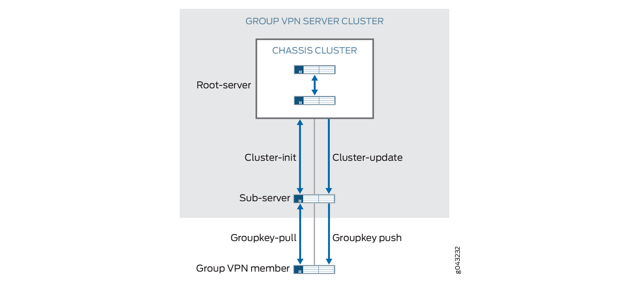
Cluster-Init Exchanges
A sub-server launches a cluster initialization (cluster-init) exchange with the root-server to obtain SA and encryption key information.
The root-server responds by sending current SA information to the
sub-server through the cluster-init exchange.
Sub-servers can then respond to registration requests from Group
VPNv2 members through a groupkey-pull exchange. The groupkey-pull exchange allows a Group VPNv2 member to request
SAs and keys shared by the group from a sub-server.
Sub-servers start a cluster-init exchange with the
root-server when:
-
The root-server is considered inactive. This is the initial assumed state of the root-server. If there is no IKE SA between the root-server and the sub-server, the sub-server initiates an IKE SA with the root-server. After a successful
cluster-initexchange, the sub-server obtains information on SAs and marks the root-server as active. -
The soft lifetime of the SA has expired.
-
A
cluster-updatemessage is received to delete all SAs. -
There are group configuration changes.
If the cluster-init exchange fails, the sub-server
retries the exchange with the root-server every 5 seconds.
Cluster-Update Messages
The groupkey-push exchange is a single rekey message
that allows a group controller/key server (GCKS) to send group SAs
and keys to members before existing group SAs expire and to update
group membership. Rekey messages are unsolicited messages sent from
the GCKS to members
Upon generating new encryption keys for an SA, the root-server
sends SA updates to all active sub-servers through a cluster-update message. After receiving a cluster-update from the root-server,
the sub-server installs the new SA and sends the new SA information
through a groupkey-push to its registered group members.
A cluster-update message sent from the root-server
requires an acknowledgement from the sub-server. If there is no acknowledgement
received from a sub-server, the root-server retransmits the cluster-update at the configured retransmission period (the default is 10 seconds).
The root-server does not retransmit if dead peer detection (DPD) indicates
that the sub-server is unavailable. If a sub-server fails to update
SA information after receiving a cluster-update, it does
not send an acknowledgement and the root-server retransmits the cluster-update message.
If the soft lifetime of an SA expires before a new SA is received
from the root-server, the sub-server sends a cluster-init message to the root-server to get all SAs and does not send a groupkey-push message to its members until it has a new update.
If the hard lifetime of an SA expires on the sub-server before it
receives a new SA, the sub-server marks the root-server inactive,
deletes all registered group members, and continues to send cluster-init messages to the root-server.
A cluster-update message can be sent to delete an
SA or a group member; this can be the result of a clear command or a configuration change. If a sub-server receives a cluster-update message to delete an SA, it sends a groupkey-push delete message to its group members and deletes the corresponding
SA. If all SAs for a group are deleted, the sub-server initiates a cluster-init exchange with the root-server. If all registered
members are deleted, the sub-server deletes all locally registered
members.
Understanding Configuration Changes with Group VPNv2 Server Clusters
Group
VPNv2 server clusters behave differently from standalone Group VPNv2 servers when there
are configuration changes that result in new encryption keys and changes to security
associations (SAs). The root-server sends SA updates or deletions to sub-servers through
cluster-update messages. The sub-servers then send
groupkey-push messages to members. Sub-servers cannot send delete
messages to group members without first receiving delete messages from the root-server.
All configuration changes must be made on the root-server first and then on sub-servers to ensure that group members receive updates or deletions as expected. Until configuration is synchronized between the servers in the Group VPNv2 server cluster, traffic loss can be expected.
Table 1 describes the effects of various configuration changes on Group VPNv2 servers.
Configuration Change |
Standalone Group VPNv2 Server Action |
Group VPNv2 Server Cluster Action |
|
|---|---|---|---|
Root-server |
Sub-server |
||
Change IKE proposal, policy, or gateway |
Delete the IKE SA for the affected gateway. For IKE proposal, policy, or gateway deletions, delete the registered members for the affected gateway. |
||
Change IPsec proposal |
Changes take effect after the traffic encryption key (TEK) rekey. |
||
Group changes: |
|||
Delete group name |
Send “delete all” to group members. Delete all IKE SAs in the group. Delete all keys in the group immediately. Delete all registered members in the group. |
Send “delete all” to sub-servers. Delete all keys in the group immediately. Mark all peers inactive. Delete sub-server IKE SAs. Delete all member IKE SAs. |
Delete all member IKE SAs. Delete all keys in the group immediately. Delete all registered members in the group. Mark peer inactive. Delete peer server IKE SAs. |
Change ID |
Send “delete all” to all members. Delete all IKE SAs in the group. Delete all keys in the group immediately. Delete all registered members in the group. Generate new keys according to the configuration. |
Send ”delete all” to sub-servers. Delete all member IKE SAs in the group. Delete all keys in the group immediately. Mark all peers inactive. Delete all peer server IKE SAs. Generate new keys according to the configuration. |
Delete all member IKE SAs in the group. Delete all keys
in the group immediately. Delete all registered members in the group.
Mark peer inactive. Delete peer server IKE SAs. Initiate new |
Add or delete IKE gateway |
No changes for additions. For deletions, delete the IKE SA and registered members for the affected gateway. |
||
Add or change anti-replay time window |
New value takes effect after the TEK rekey. |
||
Add or change no anti-replay |
New value takes effect after the TEK rekey. |
||
Server-member communication changes: |
|||
Add |
Delete all registered members. Generate key encryption key (KEK) SA. |
Generate KEK SA. Send new KEK SA to sub-server. Delete all member IKE SAs. |
Delete all registered members. |
Change |
New value takes effect after KEK rekey. |
||
Delete |
Send delete to delete all KEK SAs. Delete KEK SA. |
Send delete to sub-servers. Delete KEK SA. Delete all member IKE SAs. |
Delete KEK SA. |
IPsec SA: |
|||
Add |
Generate new TEK SA. Update the new TEK SA on members. |
Generate new TEK SA. Send new TEK SA to sub-servers. |
No action. |
Change |
New value takes effect after TEK rekey. If the match-policy changes, the current TEK is removed immediately and delete groupkey-push is sent because members need to be explicitly notified that this configuration is removed. |
If the match-policy changes, send delete to sub-servers. Delete TEK immediately. |
If the match-policy changes, delete TEK immediately. |
Delete |
Delete TEK immediately. Send delete to delete this TEK SA. |
Send delete to sub-servers. Delete TEK immediately. |
Delete TEK immediately. |
Table 2 describes the effects of changing Group VPNv2 server cluster configuration.
You must ensure that there is only one root-server in a server cluster at any time.
Server Cluster Configuration Change |
Group VPNv2 Server Cluster |
|
|---|---|---|
Root-server |
Sub-server |
|
IKE proposal, policy, or gateway (cluster peer) |
For additions, there is no change. For changes or deletions, delete the IKE SA for the affected peer. |
|
Server cluster: |
||
Add |
None. |
Send “delete all” to group members. Delete
all member IKE SAs in the group. Delete all TEKs and KEKs immediately
in the group. Delete all registered members in the group. Send |
Change role You must ensure that there is only one root-server in a server cluster at any time. |
Send “delete all” to sub-servers. Delete
all member IKE SAs in the group. Delete all TEKs and KEKs immediately
in the group. Mark all peers inactive. Delete all peer server IKE
SAs. Send |
Rekey TEK. Rekey KEK. Send new keys to sub-servers. Send new keys to members. |
Add peer |
None. |
|
Delete peer |
Mark peer inactive. Clear peer IKE SA. |
Mark peer inactive. Clear KEK. Clear TEK. Clear peer IKE SA. |
Change retransmission period |
None. |
|
Delete server cluster |
Send “delete all” to sub-servers. Delete all TEKs and KEKs immediately in the group. Mark all peers inactive. Delete all peer server IKE SAs. Generate new TEKs and KEKs according to the configuration. |
Delete all member IKE SAs in the group. Delete all TEKs and KEKs immediately in the group. Delete all registered members in the group. Mark peer inactive. Delete peer server IKE SAs. Generate new TEK and KEK according to the configuration. |
Migrating a Standalone Group VPNv2 Server to a Group VPNv2 Server Cluster
This section describes how to migrate a standalone Group VPNv2 server to a Group VPNv2 server cluster.
To migrate a standalone Group VPNv2 server to a root-server:
We highly recommend that the root-server be a chassis cluster.
To add a sub-server to the Group VPNv2 server cluster:
On the root-server, configure both a Group VPNv2 server IKE gateway and a server cluster IKE gateway for the sub-server. SAs and existing member traffic should not be impacted.
On the sub-server, configure the server cluster. Remember that the Group VPNv2 configuration must be the same on each server in the cluster, with the exception of the Group VPNv2 server IKE gateways, the server role in the cluster, and the server cluster IKE gateway configurations. On the sub-server, the configured server role in the cluster must be
sub-server. Configure a Group VPNv2 server IKE gateway and a server cluster IKE gateway for the root-server.
To delete a sub-server from the Group VPNv2 server cluster:
On the root-server, delete both the Group VPNv2 server IKE gateway and the server cluster IKE gateway configurations for the sub-server. SAs and existing member traffic should not be impacted.
Power off the sub-server.
See Also
Example: Configuring a Group VPNv2 Server Cluster and Members
This example shows how to configure a Group VPNv2 server cluster to provide group controller/key server (GCKS) redundancy and scaling to Group VPNv2 group members.
Requirements
The example uses the following hardware and software components:
Eight supported SRX Series Firewalls or vSRX Virtual Firewall instances running Junos OS Release 15.1X49-D30 or later that support Group VPNv2:
Two devices or instances are configured to operate as a chassis cluster. The chassis cluster operates as the root-server in the Group VPNv2 server cluster. The devices or instances must have the same software version and licenses.
The root-server is responsible for generating and distributing encryption keys to sub-servers in the group VPN server cluster; because of this responsibility, we recommend that the root-server be a chassis cluster.
Four other devices or instances operate as sub-servers in the Group VPNv2 server cluster.
Two other devices or instances operate as Group VPNv2 group members.
Two supported MX Series devices running Junos OS Release 15.1R2 or later that support Group VPNv2. These devices operate as Group VPNv2 group members.
A hostname, a root administrator password, and management access must be configured on each SRX Series Firewall or vSRX Virtual Firewall instance. We recommend that NTP also be configured on each device.
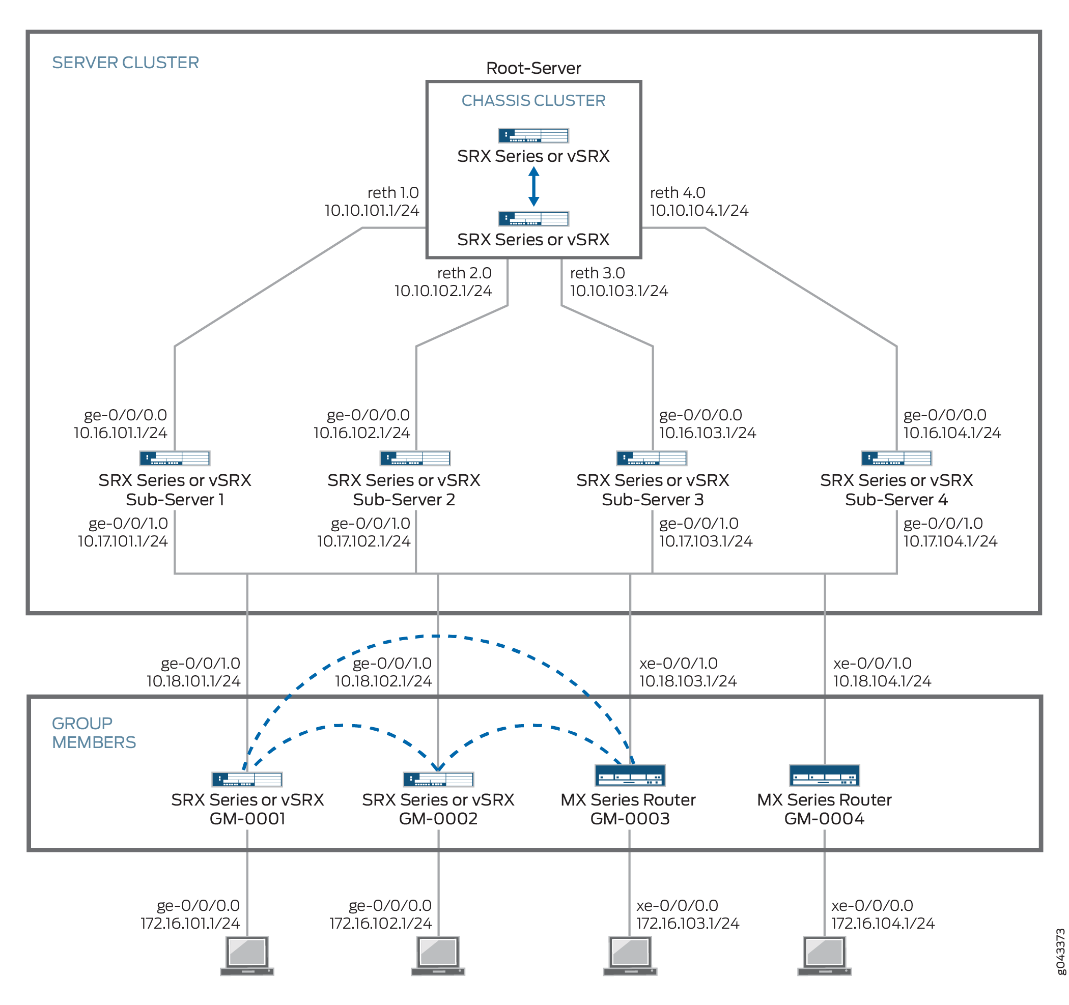
The configurations in this example focus on what is needed for Group VPNv2 operation, based on the topology shown in Figure 3. Some configurations, such as interface, routing, or chassis cluster setups, are not included here. For example, Group VPNv2 operation requires a working routing topology that allows client devices to reach their intended sites throughout the network; this example does not cover the configuration of static or dynamic routing.
Overview
In this example, the Group VPNv2 network consists of a server cluster and four members. The server cluster consists of a root-server and four sub-servers. Two of the members are SRX Series Firewalls or vSRX Virtual Firewall instances while the other two members are MX Series devices.
The group VPN SAs must be protected by a Phase 1 SA. Therefore, the group VPN configuration must include configuring IKE Phase 1 negotiations on the root-server, the sub-servers, and the group members. IKE configurations are described as follows.
On the root-server:
The IKE policy
SubSrvis used to establish Phase 1 SAs with each sub-server.An IKE gateway is configured with dead peer detection (DPD) for each sub-server.
The server cluster role is
root-serverand each sub-server is configured as an IKE gateway for the server cluster.
The root-server should be configured to support chassis cluster operation. In the example, redundant Ethernet interfaces on the root-server connect to each of the sub-servers in the server cluster; the entire chassis cluster configuration is not shown.
On each sub-server:
Two IKE policies are configured:
RootSrvis used to establish a Phase 1 SA with the root-server, andGMsis used to establish Phase 1 SAs with each group member.Preshared keys are used to secure the Phase 1 SAs between the root-server and the sub-servers and between the sub-servers and the group members. Ensure that the preshared keys used are strong keys. On the sub-servers, the preshared key configured for the IKE policy
RootSrvmust match the preshared key configured on the root-server, and the preshared key configured for the IKE policyGMsmust match the preshared key configured on the group members.An IKE gateway is configured with DPD for the root-server. In addition, an IKE gateway is configured for each group member.
The server cluster role is
sub-serverand the root-server is configured as the IKE gateway for the server cluster.
On each group member:
The IKE policy
SubSrvis used to establish Phase 1 SAs with the sub-servers.The IKE gateway configuration includes the addresses for the sub-servers.
On SRX Series Firewalls or vSRX Virtual Firewall group members, an IPsec policy is configured for the group with the LAN zone as the from-zone (incoming traffic) and the WAN zone as the to-zone (outgoing traffic). A security policy is also needed to allow traffic between the LAN and WAN zones.
The same group identifier must be configured on both the group server and the group members. In this example, the group name is GROUP_ID-0001 and the group identifier is 1. The group policy configured on the server specifies that the SA and key are applied to traffic between subnetworks in the 172.16.0.0/12 range.
Topology
Figure 3 shows the Juniper Networks devices to be configured for this example.
Configuration
- Configuring the Root-Server
- Configuring Sub-Server 1
- Configuring Sub-Server 2
- Configuring Sub-Server 3
- Configuring Sub-Server 4
- Configuring GM-0001 (SRX Series Firewall or vSRX Virtual Firewall Instance)
- Configuring GM-0002 (SRX Series Firewall or vSRX Virtual Firewall Instance)
- Configuring GM-0003 (MX Series Device)
- Configuring GM-0004 (MX Series Device)
Configuring the Root-Server
CLI Quick Configuration
To quickly configure this example, copy the
following commands, paste them into a text file, remove any line breaks,
change any details necessary to match your network configuration,
copy and paste the commands into the CLI at the [edit] hierarchy
level, and then enter commit from configuration mode.
set interfaces reth1 redundant-ether-options redundancy-group 1
set interfaces reth1 unit 0 description To_SubSrv01
set interfaces reth1 unit 0 family inet address 10.10.101.1/24
set interfaces reth2 redundant-ether-options redundancy-group 1
set interfaces reth2 unit 0 description To_SubSrv02
set interfaces reth2 unit 0 family inet address 10.10.102.1/24
set interfaces reth3 redundant-ether-options redundancy-group 1
set interfaces reth3 unit 0 description To_SubSrv03
set interfaces reth3 unit 0 family inet address 10.10.103.1/24
set interfaces reth4 redundant-ether-options redundancy-group 1
set interfaces reth4 unit 0 description To_SubSrv04
set interfaces reth4 unit 0 family inet address 10.10.104.1/24
set security zones security-zone GROUPVPN host-inbound-traffic system-services ike
set security zones security-zone GROUPVPN host-inbound-traffic system-services ssh
set security zones security-zone GROUPVPN host-inbound-traffic system-services ping
set security zones security-zone GROUPVPN interfaces reth1.0
set security zones security-zone GROUPVPN interfaces reth2.0
set security zones security-zone GROUPVPN interfaces reth3.0
set security zones security-zone GROUPVPN interfaces reth4.0
set security policies global policy 1000 match source-address any
set security policies global policy 1000 match destination-address any
set security policies global policy 1000 match application any
set security policies global policy 1000 match from-zone any
set security policies global policy 1000 match to-zone any
set security policies global policy 1000 then deny
set security policies global policy 1000 then log session-init
set security policies global policy 1000 then count
set security policies default-policy deny-all
set chassis cluster reth-count 5
set chassis cluster redundancy-group 1 node 0 priority 254
set chassis cluster redundancy-group 1 node 1 priority 1
set chassis cluster redundancy-group 0 node 0 priority 254
set chassis cluster redundancy-group 0 node 1 priority 1
set security group-vpn server ike proposal PSK-SHA256-DH14-AES256 authentication-method pre-shared-keys
set security group-vpn server ike proposal PSK-SHA256-DH14-AES256 authentication-algorithm sha-256
set security group-vpn server ike proposal PSK-SHA256-DH14-AES256 dh-group group14
set security group-vpn server ike proposal PSK-SHA256-DH14-AES256 encryption-algorithm aes-256-cbc
set security group-vpn server ike policy SubSrv mode main
set security group-vpn server ike policy SubSrv proposals PSK-SHA256-DH14-AES256
set security group-vpn server ike policy SubSrv pre-shared-key ascii-text "$ABC123"
set security group-vpn server ike gateway SubSrv01 ike-policy SubSrv
set security group-vpn server ike gateway SubSrv01 address 10.16.101.1
set security group-vpn server ike gateway SubSrv01 dead-peer-detection always-send
set security group-vpn server ike gateway SubSrv01 local-address 10.10.101.1
set security group-vpn server ike gateway SubSrv02 ike-policy SubSrv
set security group-vpn server ike gateway SubSrv02 address 10.16.102.1
set security group-vpn server ike gateway SubSrv02 dead-peer-detection always-send
set security group-vpn server ike gateway SubSrv02 local-address 10.10.102.1
set security group-vpn server ike gateway SubSrv03 ike-policy SubSrv
set security group-vpn server ike gateway SubSrv03 address 10.16.103.1
set security group-vpn server ike gateway SubSrv03 dead-peer-detection always-send
set security group-vpn server ike gateway SubSrv03 local-address 10.10.103.1
set security group-vpn server ike gateway SubSrv04 ike-policy SubSrv
set security group-vpn server ike gateway SubSrv04 address 10.16.104.1
set security group-vpn server ike gateway SubSrv04 dead-peer-detection always-send
set security group-vpn server ike gateway SubSrv04 local-address 10.10.104.1
set security group-vpn server ipsec proposal AES256-SHA256-L3600 authentication-algorithm hmac-sha-256-128
set security group-vpn server ipsec proposal AES256-SHA256-L3600 encryption-algorithm aes-256-cbc
set security group-vpn server ipsec proposal AES256-SHA256-L3600 lifetime-seconds 3600
set security group-vpn server group GROUP_ID-0001 group-id 1
set security group-vpn server group GROUP_ID-0001 member-threshold 2000
set security group-vpn server group GROUP_ID-0001 server-cluster server-role root-server
set security group-vpn server group GROUP_ID-0001 server-cluster ike-gateway SubSrv01
set security group-vpn server group GROUP_ID-0001 server-cluster ike-gateway SubSrv02
set security group-vpn server group GROUP_ID-0001 server-cluster ike-gateway SubSrv03
set security group-vpn server group GROUP_ID-0001 server-cluster ike-gateway SubSrv04
set security group-vpn server group GROUP_ID-0001 server-cluster retransmission-period 10
set security group-vpn server group GROUP_ID-0001 anti-replay-time-window 1000
set security group-vpn server group GROUP_ID-0001 server-member-communication communication-type unicast
set security group-vpn server group GROUP_ID-0001 server-member-communication encryption-algorithm aes-256-cbc
set security group-vpn server group GROUP_ID-0001 server-member-communication lifetime-seconds 7200
set security group-vpn server group GROUP_ID-0001 server-member-communication sig-hash-algorithm sha-256
set security group-vpn server group GROUP_ID-0001 ipsec-sa GROUP_ID-0001 proposal AES256-SHA256-L3600
set security group-vpn server group GROUP_ID-0001 ipsec-sa GROUP_ID-0001 match-policy 1 source 172.16.0.0/12
set security group-vpn server group GROUP_ID-0001 ipsec-sa GROUP_ID-0001 match-policy 1 destination 172.16.0.0/12
set security group-vpn server group GROUP_ID-0001 ipsec-sa GROUP_ID-0001 match-policy 1 protocol 0
Step-by-Step Procedure
The following example requires you to navigate various levels in the configuration hierarchy. For instructions on how to do that, see Using the CLI Editor in Configuration Mode in the CLI User Guide.
To configure the root-server:
Configure security zones and security policies.
[edit interfaces]
user@host# set reth1 redundant-ether-options redundancy-group 1
user@host# set reth1 unit 0 description To_SubSrv01
user@host# set reth1 unit 0 family inet address 10.10.101.1/24
user@host# set reth2 redundant-ether-options redundancy-group 1
user@host# set reth2 unit 0 description To_SubSrv02
user@host# set reth2 unit 0 family inet address 10.10.102.1/24
user@host# set reth3 redundant-ether-options redundancy-group 1
user@host# set reth3 unit 0 description To_SubSrv03
user@host# set reth3 unit 0 family inet address 10.10.103.1/24
user@host# set reth4 redundant-ether-options redundancy-group 1
user@host# set reth4 unit 0 description To_SubSrv04
user@host# set reth4 unit 0 family inet address 10.10.104.1/24
[edit security zones security-zone GROUPVPN]
user@host# set host-inbound-traffic system-services ike
user@host# set host-inbound-traffic system-services ssh
user@host# set host-inbound-traffic system-services ping
user@host# set interfaces reth1.0
user@host# set interfaces reth2.0
user@host# set interfaces reth3.0
user@host# set interfaces reth4.0
[edit security policies global]
user@host# set policy 1000 match source-address any
user@host# set policy 1000 match destination-address any
user@host# set policy 1000 match application any
user@host# set policy 1000 match from-zone any
user@host# set policy 1000 match to-zone any
user@host# set policy 1000 then deny
user@host# set policy 1000 then log session-init
user@host# set policy 1000 then count
[edit security policies]
user@host# set default-policy deny-all
Configure the chassis cluster.
[edit chassis cluster]
user@host# set reth-count 5
user@host# set redundancy-group 1 node 0 priority 254
user@host# set redundancy-group 1 node 1 priority 1
user@host# set redundancy-group 0 node 0 priority 254
user@host# set redundancy-group 0 node 1 priority 1
Configure the IKE proposal, policy, and gateway.
[edit security group-vpn server ike proposal PSK-SHA256-DH14-AES256]
user@host# set authentication-method pre-shared-keys
user@host# set group group14
user@host# set authentication-algorithm sha-256
user@host# set encryption-algorithm aes-256-cbc
[edit security group-vpn server ike policy SubSrv]
user@host# set mode main
user@host# set proposals PSK-SHA256-DH14-AES256
user@host# set pre-shared-key ascii-text "$ABC123"
[edit security group-vpn server ike gateway SubSrv01]
user@host# set ike-policy SubSrv
user@host# set address 10.16.101.1
user@host# set dead-peer-detection always-send
user@host# set local-address 10.10.101.1
[edit security group-vpn server ike gateway SubSrv02]
user@host# set ike-policy SubSrv
user@host# set address 10.16.102.1
user@host# set dead-peer-detection always-send
user@host# set local-address 10.10.102.1
[edit security group-vpn server ike gateway SubSrv03]
user@host# set ike-policy SubSrv
user@host# set address 10.16.103.1
user@host# set dead-peer-detection always-send
user@host# set local-address 10.10.103.1
[edit security group-vpn server ike gateway SubSrv04]
user@host# set ike-policy SubSrv
user@host# set address 10.16.104.1
user@host# set dead-peer-detection always-send
user@host# set local-address 10.10.104.1
Configure the IPsec SA.
[edit security group-vpn server ipsec proposal AES256-SHA256-L3600]
user@host# set authentication-algorithm hmac-sha-256-128
user@host# set encryption-algorithm aes-256-cbc
user@host# set lifetime-seconds 3600
Configure the VPN group.
[edit security group-vpn server group GROUP_ID-0001]
user@host# set group-id 1
user@host# set member-threshold 2000
user@host# set server-cluster server-role root-server
user@host# set server-cluster ike-gateway SubSrv01
user@host# set server-cluster ike-gateway SubSrv02
user@host# set server-cluster ike-gateway SubSrv03
user@host# set server-cluster ike-gateway SubSrv04
user@host# set server-cluster retransmission-period 10
user@host# set anti-replay-time-window 1000
user@host# set server-member-communication communication-type unicast
user@host# set server-member-communication encryption-algorithm aes-256-cbc
user@host# set server-member-communication lifetime-seconds 7200
user@host# set server-member-communication sig-hash-algorithm sha-256
Configure the group policy.
[edit security group-vpn server group GROUP_ID-0001]
user@host# set ipsec-sa GROUP_ID-0001 match-policy 1 source 172.16.0.0/12
user@host# set ipsec-sa GROUP_ID-0001 match-policy 1 destination 172.16.0.0/12
user@host# set ipsec-sa GROUP_ID-0001 match-policy 1 protocol 0
user@host# set ipsec-sa GROUP_ID-0001 proposal AES256-SHA256-L3600
Results
From configuration mode, confirm your configuration
by entering the show interfaces, show chassis cluster, and show security commands. If the output does not display
the intended configuration, repeat the instructions in this example
to correct the configuration.
[edit]
user@host# show interfaces
reth1 {
    redundant-ether-options {
        redundancy-group 1;
    }
    unit 0 {
        description To_SubSrv01;
        family inet {
            address 10.10.101.1/24;
        }
    }
}
reth2 {
    redundant-ether-options {
        redundancy-group 1;
    }
    unit 0 {
        description To_SubSrv02;
        family inet {
            address 10.10.102.1/24;
        }
    }
}
reth3 {
    redundant-ether-options {
        redundancy-group 1;
    }
    unit 0 {
        description To_SubSrv03;
        family inet {
            address 10.10.103.1/24;
        }
    }
}
reth4 {
    redundant-ether-options {
        redundancy-group 1;
    }
    unit 0 {
        description To_SubSrv04;
        family inet {
            address 10.10.104.1/24;
        }
    }
}
[edit]
user@host# show chassis cluster
reth-count 5;
redundancy-group 1 {
    node 0 priority 254;
    node 1 priority 1;
}
redundancy-group 0 {
    node 0 priority 254;
    node 1 priority 1;
}
[edit]
user@host# show security
group-vpn {
    server {
        ike {
            proposal PSK-SHA256-DH14-AES256 {
                authentication-method pre-shared-keys;
                authentication-algorithm sha-256;
                dh-group group14;
                encryption-algorithm aes-256-cbc;
            }
            policy SubSrv {
                mode main;
                proposals PSK-SHA256-DH14-AES256;
                pre-shared-key ascii-text "$ABC123"; ## SECRET-DATA
            }
            gateway SubSrv01 {
                ike-policy SubSrv;
                address 10.16.101.1;
                dead-peer-detection always-send;
                local-address 10.10.101.1;
            }
            gateway SubSrv02 {
                ike-policy SubSrv;
                address 10.16.102.1;
                dead-peer-detection always-send;
                local-address 10.10.102.1;
            }
            gateway SubSrv03 {
                ike-policy SubSrv;
                address 10.16.103.1;
                dead-peer-detection always-send;
                local-address 10.10.103.1;
            }
            gateway SubSrv04 {
                ike-policy SubSrv;
                address 10.16.104.1;
                dead-peer-detection always-send;
                local-address 10.10.104.1;
            }
        }
        ipsec {
            proposal AES256-SHA256-L3600 {
                authentication-algorithm hmac-sha-256-128;
                encryption-algorithm aes-256-cbc;
                lifetime-seconds 3600;
            }
        }
        group GROUP_ID-0001 {
            group-id 1;
            member-threshold 2000;
            server-cluster {
                server-role root-server;
                ike-gateway SubSrv01;
                ike-gateway SubSrv02;
                ike-gateway SubSrv03;
                ike-gateway SubSrv04;
                retransmission-period 10;
            }
            anti-replay-time-window 1000;
            server-member-communication {
                communication-type unicast;
                lifetime-seconds 7200;
                encryption-algorithm aes-256-cbc;
                sig-hash-algorithm sha-256;
            }
            ipsec-sa GROUP_ID-0001 {
                proposal AES256-SHA256-L3600;
                match-policy 1 {
                    source 172.16.0.0/12;
                    destination 172.16.0.0/12;
                    protocol 0;
                }
            }
        }
    }
}
policies {
    global {
        policy 1000 {
            match {
                source-address any;
                destination-address any;
                application any;
                from-zone any;
                to-zone any;
            }
            then {
                deny;
                log {
                    session-init;
                }
                count;
            }
        }
    }
    default-policy {
        deny-all;
    }
}
zones {
    security-zone GROUPVPN {
        host-inbound-traffic {
            system-services {
                ike;
                ssh;
                ping;
            }
        }
        interfaces {
            reth1.0;
            reth2.0;
            reth3.0;
            reth4.0;
        }
    }
}
If you are done configuring the device, enter commit from configuration mode.
Configuring Sub-Server 1
CLI Quick Configuration
To quickly configure this example, copy the
following commands, paste them into a text file, remove any line breaks,
change any details necessary to match your network configuration,
copy and paste the commands into the CLI at the [edit] hierarchy
level, and then enter commit from configuration mode.
set interfaces ge-0/0/0 unit 0 description To_RootSrv
set interfaces ge-0/0/0 unit 0 family inet address 10.16.101.1/24
set interfaces ge-0/0/1 unit 0 description To_WAN
set interfaces ge-0/0/1 unit 0 family inet address 10.17.101.1/24
set security zones security-zone GROUPVPN host-inbound-traffic system-services ike
set security zones security-zone GROUPVPN host-inbound-traffic system-services ssh
set security zones security-zone GROUPVPN host-inbound-traffic system-services ping
set security zones security-zone GROUPVPN interfaces ge-0/0/0.0
set security zones security-zone GROUPVPN interfaces ge-0/0/1.0
set security policies global policy 1000 match source-address any
set security policies global policy 1000 match destination-address any
set security policies global policy 1000 match application any
set security policies global policy 1000 match from-zone any
set security policies global policy 1000 match to-zone any
set security policies global policy 1000 then deny
set security policies global policy 1000 then log session-init
set security policies global policy 1000 then count
set security policies default-policy deny-all
set security group-vpn server ike proposal PSK-SHA256-DH14-AES256 authentication-method pre-shared-keys
set security group-vpn server ike proposal PSK-SHA256-DH14-AES256 dh-group group14
set security group-vpn server ike proposal PSK-SHA256-DH14-AES256 authentication-algorithm sha-256
set security group-vpn server ike proposal PSK-SHA256-DH14-AES256 encryption-algorithm aes-256-cbc
set security group-vpn server ike policy RootSrv mode main
set security group-vpn server ike policy RootSrv proposals PSK-SHA256-DH14-AES256
set security group-vpn server ike policy RootSrv pre-shared-key ascii-text "$ABC123"
set security group-vpn server ike policy GMs mode main
set security group-vpn server ike policy GMs proposals PSK-SHA256-DH14-AES256
set security group-vpn server ike policy GMs pre-shared-key ascii-text "$ABC123$ABC123"
set security group-vpn server ike gateway RootSrv ike-policy RootSrv
set security group-vpn server ike gateway RootSrv address 10.10.101.1
set security group-vpn server ike gateway RootSrv dead-peer-detection always-send
set security group-vpn server ike gateway RootSrv local-address 10.16.101.1
set security group-vpn server ike gateway GM-0001 ike-policy GMs
set security group-vpn server ike gateway GM-0001 address 10.18.101.1
set security group-vpn server ike gateway GM-0001 local-address 10.17.101.1
set security group-vpn server ike gateway GM-0002 ike-policy GMs
set security group-vpn server ike gateway GM-0002 address 10.18.102.1
set security group-vpn server ike gateway GM-0002 local-address 10.17.101.1
set security group-vpn server ike gateway GM-0003 ike-policy GMs
set security group-vpn server ike gateway GM-0003 address 10.18.103.1
set security group-vpn server ike gateway GM-0003 local-address 10.17.101.1
set security group-vpn server ike gateway GM-0004 ike-policy GMs
set security group-vpn server ike gateway GM-0004 address 10.18.104.1
set security group-vpn server ike gateway GM-0004 local-address 10.17.101.1
set security group-vpn server ipsec proposal AES256-SHA256-L3600 authentication-algorithm hmac-sha-256-128
set security group-vpn server ipsec proposal AES256-SHA256-L3600 encryption-algorithm aes-256-cbc
set security group-vpn server ipsec proposal AES256-SHA256-L3600 lifetime-seconds 3600
set security group-vpn server group GROUP_ID-0001 group-id 1
set security group-vpn server group GROUP_ID-0001 member-threshold 2000
set security group-vpn server group GROUP_ID-0001 server-cluster server-role sub-server
set security group-vpn server group GROUP_ID-0001 server-cluster ike-gateway RootSrv
set security group-vpn server group GROUP_ID-0001 server-cluster retransmission-period 10
set security group-vpn server group GROUP_ID-0001 ike-gateway GM-0001
set security group-vpn server group GROUP_ID-0001 ike-gateway GM-0002
set security group-vpn server group GROUP_ID-0001 ike-gateway GM-0003
set security group-vpn server group GROUP_ID-0001 ike-gateway GM-0004
set security group-vpn server group GROUP_ID-0001 anti-replay-time-window 1000
set security group-vpn server group GROUP_ID-0001 server-member-communication communication-type unicast
set security group-vpn server group GROUP_ID-0001 server-member-communication encryption-algorithm aes-256-cbc
set security group-vpn server group GROUP_ID-0001 server-member-communication lifetime-seconds 7200
set security group-vpn server group GROUP_ID-0001 server-member-communication sig-hash-algorithm sha-256
set security group-vpn server group GROUP_ID-0001 ipsec-sa GROUP_ID-0001 proposal AES256-SHA256-L3600
set security group-vpn server group GROUP_ID-0001 ipsec-sa GROUP_ID-0001 match-policy 1 source 172.16.0.0/12
set security group-vpn server group GROUP_ID-0001 ipsec-sa GROUP_ID-0001 match-policy 1 destination 172.16.0.0/12
set security group-vpn server group GROUP_ID-0001 ipsec-sa GROUP_ID-0001 match-policy 1 protocol 0
Step-by-Step Procedure
The following example requires you to navigate various levels in the configuration hierarchy. For instructions on how to do that, see Using the CLI Editor in Configuration Mode in the CLI User Guide.
To configure the sub-server in the Group VPNv2 server cluster:
Configure interfaces, security zones, and security policies.
[edit interfaces]
user@host# set ge-0/0/0 unit 0 description To_RootSrv
user@host# set ge-0/0/0 unit 0 family inet address 10.16.101.1/24
user@host# set ge-0/0/1 unit 0 description To_WAN
user@host# set ge-0/0/1 unit 0 family inet address 10.17.101.1/24
[edit security zones security-zone GROUPVPN]
user@host# set host-inbound-traffic system-services ike
user@host# set host-inbound-traffic system-services ssh
user@host# set host-inbound-traffic system-services ping
user@host# set interfaces ge-0/0/0.0
user@host# set interfaces ge-0/0/1.0
[edit security policies global]
user@host# set policy 1000 match source-address any
user@host# set policy 1000 match destination-address any
user@host# set policy 1000 match application any
user@host# set policy 1000 match from-zone any
user@host# set policy 1000 match to-zone any
user@host# set policy 1000 then deny
user@host# set policy 1000 then log session-init
user@host# set policy 1000 then count
[edit security policies]
user@host# set default-policy deny-all
Configure the IKE proposal, policy, and gateway.
[edit security group-vpn server ike proposal PSK-SHA256-DH14-AES256]
user@host# set authentication-method pre-shared-keys
user@host# set group group14
user@host# set authentication-algorithm sha-256
user@host# set encryption-algorithm aes-256-cbc
[edit security group-vpn server ike policy RootSrv]
user@host# set mode main
user@host# set proposals PSK-SHA256-DH14-AES256
user@host# set pre-shared-key ascii-text "$ABC123"
[edit security group-vpn server ike policy GMs]
user@host# set mode main
user@host# set proposals PSK-SHA256-DH14-AES256
user@host# set pre-shared-key ascii-text "$ABC123$ABC123"
[edit security group-vpn server ike gateway RootSrv]
user@host# set ike-policy RootSrv
user@host# set address 10.10.101.1
user@host# set dead-peer-detection always-send
user@host# set local-address 10.16.101.1
[edit security group-vpn server ike gateway GM-0001]
user@host# set ike-policy GMs
user@host# set address 10.18.101.1
user@host# set local-address 10.17.101.1
[edit security group-vpn server ike gateway GM-0002]
user@host# set ike-policy GMs
user@host# set address 10.18.102.1
user@host# set local-address 10.17.101.1
[edit security group-vpn server ike gateway GM-0003]
user@host# set ike-policy GMs
user@host# set address 10.18.103.1
user@host# set local-address 10.17.101.1
[edit security group-vpn server ike gateway GM-0004]
user@host# set ike-policy GMs
user@host# set address 10.18.104.1
user@host# set local-address 10.17.101.1
Configure the IPsec SA.
[edit security group-vpn server ipsec proposal AES256-SHA256-L3600]
user@host# set authentication-algorithm hmac-sha-256-128
user@host# set encryption-algorithm aes-256-cbc
user@host# set lifetime-seconds 3600
Configure the VPN group.
[edit security group-vpn server group GROUP_ID-0001]
user@host# set group-id 1
user@host# set member-threshold 2000
user@host# set server-cluster server-role sub-server
user@host# set server-cluster ike-gateway RootSrv
user@host# set server-cluster retransmission-period 10
user@host# set ike-gateway GM-0001
user@host# set ike-gateway GM-0002
user@host# set ike-gateway GM-0003
user@host# set ike-gateway GM-0004
user@host# set anti-replay-time-window 1000
user@host# set server-member-communication communication-type unicast
user@host# set server-member-communication encryption-algorithm aes-256-cbc
user@host# set server-member-communication lifetime-seconds 7200
user@host# set server-member-communication sig-hash-algorithm sha-256
user@host# set ipsec-sa GROUP_ID-0001 proposal AES256-SHA256-L3600
Configure the group policy.
[edit security group-vpn server group GROUP_ID-0001]
user@host# set ipsec-sa GROUP_ID-0001 match-policy 1 source 172.16.0.0/12
user@host# set ipsec-sa GROUP_ID-0001 match-policy 1 destination 172.16.0.0/12
user@host# set ipsec-sa GROUP_ID-0001 match-policy 1 protocol 0
Results
From configuration mode, confirm your configuration
by entering the show interfacesand show security commands. If the output does not display the intended configuration,
repeat the instructions in this example to correct the configuration.
[edit]
user@host# show interfaces
ge-0/0/0 {
    unit 0 {
        description To_RootSrv;
        family inet {
            address 10.16.101.1/24;
        }
    }
}
ge-0/0/1 {
    unit 0 {
        description To_WAN;
        family inet {
            address 10.17.101.1/24;
        }
    }
}
[edit]
user@host# show security
group-vpn {
    server {
        ike {
            proposal PSK-SHA256-DH14-AES256 {
                authentication-method pre-shared-keys;
                authentication-algorithm sha-256;
                dh-group group14;
                encryption-algorithm aes-256-cbc;
            }
            policy RootSrv {
                mode main;
                proposals PSK-SHA256-DH14-AES256;
                pre-shared-key ascii-text "$ABC123"; ## SECRET-DATA
            }
            policy GMs {
                mode main;
                proposals PSK-SHA256-DH14-AES256;
                pre-shared-key ascii-text "$ABC123$ABC123"; ## SECRET-DATA
            }
            gateway RootSrv {
                ike-policy RootSrv;
                address 10.10.101.1;
                dead-peer-detection always-send;
                local-address 10.16.101.1;
            }
            gateway GM-0001 {
                ike-policy GMs;
                address 10.18.101.1;
                local-address 10.17.101.1;
            }
            gateway GM-0002 {
                ike-policy GMs;
                address 10.18.102.1;
                local-address 10.17.101.1;
            }
            gateway GM-0003 {
                ike-policy GMs;
                address 10.18.103.1;
                local-address 10.17.101.1;
            }
            gateway GM-0004 {
                ike-policy GMs;
                address 10.18.104.1;
                local-address 10.17.101.1;
            }
        }
        ipsec {
            proposal AES256-SHA256-L3600 {
                authentication-algorithm hmac-sha-256-128;
                encryption-algorithm aes-256-cbc;
                lifetime-seconds 3600;
            }
        }
        group GROUP_ID-0001 {
            group-id 1;
            member-threshold 2000;
            server-cluster {
                server-role sub-server;
                ike-gateway RootSrv;
                retransmission-period 10;
            }
            ike-gateway GM-0001;
            ike-gateway GM-0002;
            ike-gateway GM-0003;
            ike-gateway GM-0004;
            anti-replay-time-window 1000;
            server-member-communication {
                communication-type unicast;
                lifetime-seconds 7200;
                encryption-algorithm aes-256-cbc;
                sig-hash-algorithm sha-256;
            }
            ipsec-sa GROUP_ID-0001 {
                proposal AES256-SHA256-L3600;
                match-policy 1 {
                    source 172.16.0.0/12;
                    destination 172.16.0.0/12;
                    protocol 0;
                }
            }
        }
    }
}
policies {
    global {
        policy 1000 {
            match {
                source-address any;
                destination-address any;
                application any;
                from-zone any;
                to-zone any;
            }
            then {
                deny;
                log {
                    session-init;
                }
                count;
            }
        }
    }
    default-policy {
        deny-all;
    }
}
zones {
    security-zone GROUPVPN {
        host-inbound-traffic {
            system-services {
                ike;
                ssh;
                ping;
            }
        }
        interfaces {
            ge-0/0/0.0;
            ge-0/0/1.0;
        }
    }
}
If you are done configuring the device, enter commit from configuration mode.
Configuring Sub-Server 2
CLI Quick Configuration
To quickly configure this example, copy the
following commands, paste them into a text file, remove any line breaks,
change any details necessary to match your network configuration,
copy and paste the commands into the CLI at the [edit] hierarchy
level, and then enter commit from configuration mode.
set interfaces ge-0/0/0 unit 0 description To_RootSrv
set interfaces ge-0/0/0 unit 0 family inet address 10.16.102.1/24
set interfaces ge-0/0/1 unit 0 description To_WAN
set interfaces ge-0/0/1 unit 0 family inet address 10.17.102.1/24
set security zones security-zone GROUPVPN host-inbound-traffic system-services ike
set security zones security-zone GROUPVPN host-inbound-traffic system-services ssh
set security zones security-zone GROUPVPN host-inbound-traffic system-services ping
set security zones security-zone GROUPVPN interfaces ge-0/0/0.0
set security zones security-zone GROUPVPN interfaces ge-0/0/1.0
set security policies global policy 1000 match source-address any
set security policies global policy 1000 match destination-address any
set security policies global policy 1000 match application any
set security policies global policy 1000 match from-zone any
set security policies global policy 1000 match to-zone any
set security policies global policy 1000 then deny
set security policies global policy 1000 then log session-init
set security policies global policy 1000 then count
set security policies default-policy deny-all
set security group-vpn server ike proposal PSK-SHA256-DH14-AES256 authentication-method pre-shared-keys
set security group-vpn server ike proposal PSK-SHA256-DH14-AES256 dh-group group14
set security group-vpn server ike proposal PSK-SHA256-DH14-AES256 authentication-algorithm sha-256
set security group-vpn server ike proposal PSK-SHA256-DH14-AES256 encryption-algorithm aes-256-cbc
set security group-vpn server ike policy RootSrv mode main
set security group-vpn server ike policy RootSrv proposals PSK-SHA256-DH14-AES256
set security group-vpn server ike policy RootSrv pre-shared-key ascii-text "$ABC123"
set security group-vpn server ike policy GMs mode main
set security group-vpn server ike policy GMs proposals PSK-SHA256-DH14-AES256
set security group-vpn server ike policy GMs pre-shared-key ascii-text "$ABC123$ABC123"
set security group-vpn server ike gateway RootSrv ike-policy RootSrv
set security group-vpn server ike gateway RootSrv address 10.10.102.1
set security group-vpn server ike gateway RootSrv dead-peer-detection always-send
set security group-vpn server ike gateway RootSrv local-address 10.16.102.1
set security group-vpn server ike gateway GM-0001 ike-policy GMs
set security group-vpn server ike gateway GM-0001 address 10.18.101.1
set security group-vpn server ike gateway GM-0001 local-address 10.17.102.1
set security group-vpn server ike gateway GM-0002 ike-policy GMs
set security group-vpn server ike gateway GM-0002 address 10.18.102.1
set security group-vpn server ike gateway GM-0002 local-address 10.17.102.1
set security group-vpn server ike gateway GM-0003 ike-policy GMs
set security group-vpn server ike gateway GM-0003 address 10.18.103.1
set security group-vpn server ike gateway GM-0003 local-address 10.17.102.1
set security group-vpn server ike gateway GM-0004 ike-policy GMs
set security group-vpn server ike gateway GM-0004 address 10.18.104.1
set security group-vpn server ike gateway GM-0004 local-address 10.17.102.1
set security group-vpn server ipsec proposal AES256-SHA256-L3600 authentication-algorithm hmac-sha-256-128
set security group-vpn server ipsec proposal AES256-SHA256-L3600 encryption-algorithm aes-256-cbc
set security group-vpn server ipsec proposal AES256-SHA256-L3600 lifetime-seconds 3600
set security group-vpn server group GROUP_ID-0001 group-id 1
set security group-vpn server group GROUP_ID-0001 member-threshold 2000
set security group-vpn server group GROUP_ID-0001 server-cluster server-role sub-server
set security group-vpn server group GROUP_ID-0001 server-cluster ike-gateway RootSrv
set security group-vpn server group GROUP_ID-0001 server-cluster retransmission-period 10
set security group-vpn server group GROUP_ID-0001 ike-gateway GM-0001
set security group-vpn server group GROUP_ID-0001 ike-gateway GM-0002
set security group-vpn server group GROUP_ID-0001 ike-gateway GM-0003
set security group-vpn server group GROUP_ID-0001 ike-gateway GM-0004
set security group-vpn server group GROUP_ID-0001 anti-replay-time-window 1000
set security group-vpn server group GROUP_ID-0001 server-member-communication communication-type unicast
set security group-vpn server group GROUP_ID-0001 server-member-communication encryption-algorithm aes-256-cbc
set security group-vpn server group GROUP_ID-0001 server-member-communication lifetime-seconds 7200
set security group-vpn server group GROUP_ID-0001 server-member-communication sig-hash-algorithm sha-256
set security group-vpn server group GROUP_ID-0001 ipsec-sa GROUP_ID-0001 proposal AES256-SHA256-L3600
set security group-vpn server group GROUP_ID-0001 ipsec-sa GROUP_ID-0001 match-policy 1 source 172.16.0.0/12
set security group-vpn server group GROUP_ID-0001 ipsec-sa GROUP_ID-0001 match-policy 1 destination 172.16.0.0/12
set security group-vpn server group GROUP_ID-0001 ipsec-sa GROUP_ID-0001 match-policy 1 protocol 0
Step-by-Step Procedure
The following example requires you to navigate various levels in the configuration hierarchy. For instructions on how to do that, see Using the CLI Editor in Configuration Mode in the CLI User Guide.
To configure the sub-server in the Group VPNv2 server cluster:
Configure interfaces, security zones, and security policies.
[edit interfaces]
user@host# set ge-0/0/0 unit 0 description To_RootSrv
user@host# set ge-0/0/0 unit 0 family inet address 10.16.102.1/24
user@host# set ge-0/0/1 unit 0 description To_WAN
user@host# set ge-0/0/1 unit 0 family inet address 10.17.102.1/24
[edit security zones security-zone GROUPVPN]
user@host# set host-inbound-traffic system-services ike
user@host# set host-inbound-traffic system-services ssh
user@host# set host-inbound-traffic system-services ping
user@host# set interfaces ge-0/0/0.0
user@host# set interfaces ge-0/0/1.0
[edit security policies global]
user@host# set policy 1000 match source-address any
user@host# set policy 1000 match destination-address any
user@host# set policy 1000 match application any
user@host# set policy 1000 match from-zone any
user@host# set policy 1000 match to-zone any
user@host# set policy 1000 then deny
user@host# set policy 1000 then log session-init
user@host# set policy 1000 then count
[edit security policies]
user@host# set default-policy deny-all
Configure the IKE proposal, policy, and gateway.
[edit security group-vpn server ike proposal PSK-SHA256-DH14-AES256]
user@host# set authentication-method pre-shared-keys
user@host# set group group14
user@host# set authentication-algorithm sha-256
user@host# set encryption-algorithm aes-256-cbc
[edit security group-vpn server ike policy RootSrv]
user@host# set mode main
user@host# set proposals PSK-SHA256-DH14-AES256
user@host# set pre-shared-key ascii-text "$ABC123"
[edit security group-vpn server ike policy GMs]
user@host# set mode main
user@host# set proposals PSK-SHA256-DH14-AES256
user@host# set pre-shared-key ascii-text "$ABC123$ABC123"
[edit security group-vpn server ike gateway RootSrv]
user@host# set ike-policy RootSrv
user@host# set address 10.10.102.1
user@host# set dead-peer-detection always-send
user@host# set local-address 10.16.102.1
[edit security group-vpn server ike gateway GM-0001]
user@host# set ike-policy GMs
user@host# set address 10.18.101.1
user@host# set local-address 10.17.102.1
[edit security group-vpn server ike gateway GM-0002]
user@host# set ike-policy GMs
user@host# set address 10.18.102.1
user@host# set local-address 10.17.102.1
[edit security group-vpn server ike gateway GM-0003]
user@host# set ike-policy GMs
user@host# set address 10.18.103.1
user@host# set local-address 10.17.102.1
[edit security group-vpn server ike gateway GM-0004]
user@host# set ike-policy GMs
user@host# set address 10.18.104.1
user@host# set local-address 10.17.102.1
Configure the IPsec SA.
[edit security group-vpn server ipsec proposal AES256-SHA256-L3600]
user@host# set authentication-algorithm hmac-sha-256-128
user@host# set encryption-algorithm aes-256-cbc
user@host# set lifetime-seconds 3600
Configure the VPN group.
[edit security group-vpn server group GROUP_ID-0001]
user@host# set group-id 1
user@host# set member-threshold 2000
user@host# set server-cluster server-role sub-server
user@host# set server-cluster ike-gateway RootSrv
user@host# set server-cluster retransmission-period 10
user@host# set ike-gateway GM-0001
user@host# set ike-gateway GM-0002
user@host# set ike-gateway GM-0003
user@host# set ike-gateway GM-0004
user@host# set anti-replay-time-window 1000
user@host# set server-member-communication communication-type unicast
user@host# set server-member-communication encryption-algorithm aes-256-cbc
user@host# set server-member-communication lifetime-seconds 7200
user@host# set server-member-communication sig-hash-algorithm sha-256
Configure the group policy.
[edit security group-vpn server group GROUP_ID-0001]
user@host# set ipsec-sa GROUP_ID-0001 match-policy 1 source 172.16.0.0/12
user@host# set ipsec-sa GROUP_ID-0001 match-policy 1 destination 172.16.0.0/12
user@host# set ipsec-sa GROUP_ID-0001 match-policy 1 protocol 0
user@host# set ipsec-sa GROUP_ID-0001 proposal AES256-SHA256-L3600
Results
From configuration mode, confirm your configuration
by entering the show interfaces and show security commands. If the output does not display the intended configuration,
repeat the instructions in this example to correct the configuration.
[edit]
user@host# show interfaces
ge-0/0/0 {
    unit 0 {
        description To_RootSrv;
        family inet {
            address 10.16.102.1/24;
        }
    }
}
ge-0/0/1 {
    unit 0 {
        description To_WAN;
        family inet {
            address 10.17.102.1/24;
        }
    }
}
[edit]
user@host# show security
group-vpn {
    server {
        ike {
            proposal PSK-SHA256-DH14-AES256 {
                authentication-method pre-shared-keys;
                authentication-algorithm sha-256;
                dh-group group14;
                encryption-algorithm aes-256-cbc;
            }
            policy RootSrv {
                mode main;
                proposals PSK-SHA256-DH14-AES256;
                pre-shared-key ascii-text "$ABC123"; ## SECRET-DATA
            }
            policy GMs {
                mode main;
                proposals PSK-SHA256-DH14-AES256;
                pre-shared-key ascii-text "$ABC123$ABC123"; ## SECRET-DATA
            }
            gateway RootSrv {
                ike-policy RootSrv;
                address 10.10.102.1;
                dead-peer-detection always-send;
                local-address 10.16.102.1;
            }
            gateway GM-0001 {
                ike-policy GMs;
                address 10.18.101.1;
                local-address 10.17.102.1;
            }
            gateway GM-0002 {
                ike-policy GMs;
                address 10.18.102.1;
                local-address 10.17.102.1;
            }
            gateway GM-0003 {
                ike-policy GMs;
                address 10.18.103.1;
                local-address 10.17.102.1;
            }
            gateway GM-0004 {
                ike-policy GMs;
                address 10.18.104.1;
                local-address 10.17.102.1;
            }
        }
        ipsec {
            proposal AES256-SHA256-L3600 {
                authentication-algorithm hmac-sha-256-128;
                encryption-algorithm aes-256-cbc;
                lifetime-seconds 3600;
            }
        }
        group GROUP_ID-0001 {
            group-id 1;
            member-threshold 2000;
            server-cluster {
                server-role sub-server;
                ike-gateway RootSrv;
                retransmission-period 10;
            }
            ike-gateway GM-0001;
            ike-gateway GM-0002;
            ike-gateway GM-0003;
            ike-gateway GM-0004;
            anti-replay-time-window 1000;
            server-member-communication {
                communication-type unicast;
                lifetime-seconds 7200;
                encryption-algorithm aes-256-cbc;
                sig-hash-algorithm sha-256;
            }
            ipsec-sa GROUP_ID-0001 {
                proposal AES256-SHA256-L3600;
                match-policy 1 {
                    source 172.16.0.0/12;
                    destination 172.16.0.0/12;
                    protocol 0;
                }
            }
        }
    }
}
policies {
    global {
        policy 1000 {
            match {
                source-address any;
                destination-address any;
                application any;
                from-zone any;
                to-zone any;
            }
            then {
                deny;
                log {
                    session-init;
                }
                count;
            }
        }
    }
    default-policy {
        deny-all;
    }
}
zones {
    security-zone GROUPVPN {
        host-inbound-traffic {
            system-services {
                ike;
                ssh;
                ping;
            }
        }
        interfaces {
            ge-0/0/0.0;
            ge-0/0/1.0;
        }
    }
}
If you are done configuring the device, enter commit from configuration mode.
Configuring Sub-Server 3
CLI Quick Configuration
To quickly configure this example, copy the
following commands, paste them into a text file, remove any line breaks,
change any details necessary to match your network configuration,
copy and paste the commands into the CLI at the [edit] hierarchy
level, and then enter commit from configuration mode.
set interfaces ge-0/0/0 unit 0 description To_RootSrv
set interfaces ge-0/0/0 unit 0 family inet address 10.16.103.1/24
set interfaces ge-0/0/1 unit 0 description To_WAN
set interfaces ge-0/0/1 unit 0 family inet address 10.17.103.1/24
set security zones security-zone GROUPVPN host-inbound-traffic system-services ike
set security zones security-zone GROUPVPN host-inbound-traffic system-services ssh
set security zones security-zone GROUPVPN host-inbound-traffic system-services ping
set security zones security-zone GROUPVPN interfaces ge-0/0/0.0
set security zones security-zone GROUPVPN interfaces ge-0/0/1.0
set security policies global policy 1000 match source-address any
set security policies global policy 1000 match destination-address any
set security policies global policy 1000 match application any
set security policies global policy 1000 match from-zone any
set security policies global policy 1000 match to-zone any
set security policies global policy 1000 then deny
set security policies global policy 1000 then log session-init
set security policies global policy 1000 then count
set security policies default-policy deny-all
set security group-vpn server ike proposal PSK-SHA256-DH14-AES256 authentication-method pre-shared-keys
set security group-vpn server ike proposal PSK-SHA256-DH14-AES256 dh-group group14
set security group-vpn server ike proposal PSK-SHA256-DH14-AES256 authentication-algorithm sha-256
set security group-vpn server ike proposal PSK-SHA256-DH14-AES256 encryption-algorithm aes-256-cbc
set security group-vpn server ike policy RootSrv mode main
set security group-vpn server ike policy RootSrv proposals PSK-SHA256-DH14-AES256
set security group-vpn server ike policy RootSrv pre-shared-key ascii-text "$ABC123"
set security group-vpn server ike policy GMs mode main
set security group-vpn server ike policy GMs proposals PSK-SHA256-DH14-AES256
set security group-vpn server ike policy GMs pre-shared-key ascii-text "$ABC123$ABC123"
set security group-vpn server ike gateway RootSrv ike-policy RootSrv
set security group-vpn server ike gateway RootSrv address 10.10.103.1
set security group-vpn server ike gateway RootSrv dead-peer-detection always-send
set security group-vpn server ike gateway RootSrv local-address 10.16.103.1
set security group-vpn server ike gateway GM-0001 ike-policy GMs
set security group-vpn server ike gateway GM-0001 address 10.18.101.1
set security group-vpn server ike gateway GM-0001 local-address 10.17.103.1
set security group-vpn server ike gateway GM-0002 ike-policy GMs
set security group-vpn server ike gateway GM-0002 address 10.18.102.1
set security group-vpn server ike gateway GM-0002 local-address 10.17.103.1
set security group-vpn server ike gateway GM-0003 ike-policy GMs
set security group-vpn server ike gateway GM-0003 address 10.18.103.1
set security group-vpn server ike gateway GM-0003 local-address 10.17.103.1
set security group-vpn server ike gateway GM-0004 ike-policy GMs
set security group-vpn server ike gateway GM-0004 address 10.18.104.1
set security group-vpn server ike gateway GM-0004 local-address 10.17.103.1
set security group-vpn server ipsec proposal AES256-SHA256-L3600 authentication-algorithm hmac-sha-256-128
set security group-vpn server ipsec proposal AES256-SHA256-L3600 encryption-algorithm aes-256-cbc
set security group-vpn server ipsec proposal AES256-SHA256-L3600 lifetime-seconds 3600
set security group-vpn server group GROUP_ID-0001 group-id 1
set security group-vpn server group GROUP_ID-0001 member-threshold 2000
set security group-vpn server group GROUP_ID-0001 server-cluster server-role sub-server
set security group-vpn server group GROUP_ID-0001 server-cluster ike-gateway RootSrv
set security group-vpn server group GROUP_ID-0001 server-cluster retransmission-period 10
set security group-vpn server group GROUP_ID-0001 ike-gateway GM-0001
set security group-vpn server group GROUP_ID-0001 ike-gateway GM-0002
set security group-vpn server group GROUP_ID-0001 ike-gateway GM-0003
set security group-vpn server group GROUP_ID-0001 ike-gateway GM-0004
set security group-vpn server group GROUP_ID-0001 anti-replay-time-window 1000
set security group-vpn server group GROUP_ID-0001 server-member-communication communication-type unicast
set security group-vpn server group GROUP_ID-0001 server-member-communication encryption-algorithm aes-256-cbc
set security group-vpn server group GROUP_ID-0001 server-member-communication lifetime-seconds 7200
set security group-vpn server group GROUP_ID-0001 server-member-communication sig-hash-algorithm sha-256
set security group-vpn server group GROUP_ID-0001 ipsec-sa GROUP_ID-0001 proposal AES256-SHA256-L3600
set security group-vpn server group GROUP_ID-0001 ipsec-sa GROUP_ID-0001 match-policy 1 source 172.16.0.0/12
set security group-vpn server group GROUP_ID-0001 ipsec-sa GROUP_ID-0001 match-policy 1 destination 172.16.0.0/12
set security group-vpn server group GROUP_ID-0001 ipsec-sa GROUP_ID-0001 match-policy 1 protocol 0
Step-by-Step Procedure
The following example requires you to navigate various levels in the configuration hierarchy. For instructions on how to do that, see Using the CLI Editor in Configuration Mode in the CLI User Guide.
To configure the sub-server in the Group VPNv2 server cluster:
Configure interfaces, security zones, and security policies.
[edit interfaces]
user@host# set ge-0/0/0 unit 0 description To_RootSrv
user@host# set ge-0/0/0 unit 0 family inet address 10.16.103.1/24
user@host# set ge-0/0/1 unit 0 description To_WAN
user@host# set ge-0/0/1 unit 0 family inet address 10.17.103.1/24
[edit security zones security-zone GROUPVPN]
user@host# set host-inbound-traffic system-services ike
user@host# set host-inbound-traffic system-services ssh
user@host# set host-inbound-traffic system-services ping
user@host# set interfaces ge-0/0/0.0
user@host# set interfaces ge-0/0/1.0
[edit security policies global]
user@host# set policy 1000 match source-address any
user@host# set policy 1000 match destination-address any
user@host# set policy 1000 match application any
user@host# set policy 1000 match from-zone any
user@host# set policy 1000 match to-zone any
user@host# set policy 1000 then deny
user@host# set policy 1000 then log session-init
user@host# set policy 1000 then count
[edit security policies]
user@host# set default-policy deny-all
Configure the IKE proposal, policy, and gateway.
[edit security group-vpn server ike proposal PSK-SHA256-DH14-AES256]
user@host# set authentication-method pre-shared-keys
user@host# set group group14
user@host# set authentication-algorithm sha-256
user@host# set encryption-algorithm aes-256-cbc
[edit security group-vpn server ike policy RootSrv]
user@host# set mode main
user@host# set proposals PSK-SHA256-DH14-AES256
user@host# set pre-shared-key ascii-text "$ABC123"
[edit security group-vpn server ike policy GMs]
user@host# set mode main
user@host# set proposals PSK-SHA256-DH14-AES256
user@host# set pre-shared-key ascii-text "$ABC123$ABC123"
[edit security group-vpn server ike gateway RootSrv]
user@host# set ike-policy RootSrv
user@host# set address 10.10.103.1
user@host# set dead-peer-detection always-send
user@host# set local-address 10.16.103.1
[edit security group-vpn server ike gateway GM-0001]
user@host# set ike-policy GMs
user@host# set address 10.18.101.1
user@host# set local-address 10.17.103.1
[edit security group-vpn server ike gateway GM-0002]
user@host# set ike-policy GMs
user@host# set address 10.18.102.1
user@host# set local-address 10.17.103.1
[edit security group-vpn server ike gateway GM-0003]
user@host# set ike-policy GMs
user@host# set address 10.18.103.1
user@host# set local-address 10.17.103.1
[edit security group-vpn server ike gateway GM-0004]
user@host# set ike-policy GMs
user@host# set address 10.18.104.1
user@host# set local-address 10.17.103.1
Configure the IPsec SA.
[edit security group-vpn server ipsec proposal AES256-SHA256-L3600]
user@host# set authentication-algorithm hmac-sha-256-128
user@host# set encryption-algorithm aes-256-cbc
user@host# set lifetime-seconds 3600
Configure the VPN group.
[edit security group-vpn server group GROUP_ID-0001]
user@host# set group-id 1
user@host# set member-threshold 2000
user@host# set server-cluster server-role sub-server
user@host# set server-cluster ike-gateway RootSrv
user@host# set server-cluster retransmission-period 10
user@host# set ike-gateway GM-0001
user@host# set ike-gateway GM-0002
user@host# set ike-gateway GM-0003
user@host# set ike-gateway GM-0004
user@host# set anti-replay-time-window 1000
user@host# set server-member-communication communication-type unicast
user@host# set server-member-communication encryption-algorithm aes-256-cbc
user@host# set server-member-communication lifetime-seconds 7200
user@host# set server-member-communication sig-hash-algorithm sha-256
Configure the group policy.
[edit security group-vpn server group GROUP_ID-0001]
user@host# set ipsec-sa GROUP_ID-0001 match-policy 1 source 172.16.0.0/12
user@host# set ipsec-sa GROUP_ID-0001 match-policy 1 destination 172.16.0.0/12
user@host# set ipsec-sa GROUP_ID-0001 match-policy 1 protocol 0
user@host# set ipsec-sa GROUP_ID-0001 proposal AES256-SHA256-L3600
Results
From configuration mode, confirm your configuration
by entering the show interfaces and show security commands. If the output does not display the intended configuration,
repeat the instructions in this example to correct the configuration.
[edit]
user@host# show interfaces
ge-0/0/0 {
    unit 0 {
        description To_RootSrv;
        family inet {
            address 10.16.103.1/24;
        }
    }
}
ge-0/0/1 {
    unit 0 {
        description To_WAN;
        family inet {
            address 10.17.103.1/24;
        }
    }
}
[edit]
user@host# show security
group-vpn {
    server {
        ike {
            proposal PSK-SHA256-DH14-AES256 {
                authentication-method pre-shared-keys;
                authentication-algorithm sha-256;
                dh-group group14;
                encryption-algorithm aes-256-cbc;
            }
            policy RootSrv {
                mode main;
                proposals PSK-SHA256-DH14-AES256;
                pre-shared-key ascii-text "$ABC123"; ## SECRET-DATA
            }
            policy GMs {
                mode main;
                proposals PSK-SHA256-DH14-AES256;
                pre-shared-key ascii-text "$ABC123$ABC123"; ## SECRET-DATA
            }
            gateway RootSrv {
                ike-policy RootSrv;
                address 10.10.103.1;
                dead-peer-detection always-send;
                local-address 10.16.103.1;
            }
            gateway GM-0001 {
                ike-policy GMs;
                address 10.18.101.1;
                local-address 10.17.103.1;
            }
            gateway GM-0002 {
                ike-policy GMs;
                address 10.18.102.1;
                local-address 10.17.103.1;
            }
            gateway GM-0003 {
                ike-policy GMs;
                address 10.18.103.1;
                local-address 10.17.103.1;
            }
            gateway GM-0004 {
                ike-policy GMs;
                address 10.18.104.1;
                local-address 10.17.103.1;
            }
        }
        ipsec {
            proposal AES256-SHA256-L3600 {
                authentication-algorithm hmac-sha-256-128;
                encryption-algorithm aes-256-cbc;
                lifetime-seconds 3600;
            }
        }
        group GROUP_ID-0001 {
            group-id 1;
            member-threshold 2000;
            server-cluster {
                server-role sub-server;
                ike-gateway RootSrv;
                retransmission-period 10;
            }
            ike-gateway GM-0001;
            ike-gateway GM-0002;
            ike-gateway GM-0003;
            ike-gateway GM-0004;
            anti-replay-time-window 1000;
            server-member-communication {
                communication-type unicast;
                lifetime-seconds 7200;
                encryption-algorithm aes-256-cbc;
                sig-hash-algorithm sha-256;
            }
            ipsec-sa GROUP_ID-0001 {
                proposal AES256-SHA256-L3600;
                match-policy 1 {
                    source 172.16.0.0/12;
                    destination 172.16.0.0/12;
                    protocol 0;
                }
            }
        }
    }
}
policies {
    global {
        policy 1000 {
            match {
                source-address any;
                destination-address any;
                application any;
                from-zone any;
                to-zone any;
            }
            then {
                deny;
                log {
                    session-init;
                }
                count;
            }
        }
    }
    default-policy {
        deny-all;
    }
}
zones {
    security-zone GROUPVPN {
        host-inbound-traffic {
            system-services {
                ike;
                ssh;
                ping;
            }
        }
        interfaces {
            ge-0/0/0.0;
            ge-0/0/1.0;
        }
    }
}
If you are done configuring the device, enter commit from configuration mode.
Configuring Sub-Server 4
CLI Quick Configuration
To quickly configure this example, copy the
following commands, paste them into a text file, remove any line breaks,
change any details necessary to match your network configuration,
copy and paste the commands into the CLI at the [edit] hierarchy
level, and then enter commit from configuration mode.
set interfaces ge-0/0/0 unit 0 description To_RootSrv
set interfaces ge-0/0/0 unit 0 family inet address 10.16.104.1/24
set interfaces ge-0/0/1 unit 0 description To_WAN
set interfaces ge-0/0/1 unit 0 family inet address 10.17.104.1/24
set security zones security-zone GROUPVPN host-inbound-traffic system-services ike
set security zones security-zone GROUPVPN host-inbound-traffic system-services ssh
set security zones security-zone GROUPVPN host-inbound-traffic system-services ping
set security zones security-zone GROUPVPN interfaces ge-0/0/0.0
set security zones security-zone GROUPVPN interfaces ge-0/0/1.0
set security policies global policy 1000 match source-address any
set security policies global policy 1000 match destination-address any
set security policies global policy 1000 match application any
set security policies global policy 1000 match from-zone any
set security policies global policy 1000 match to-zone any
set security policies global policy 1000 then deny
set security policies global policy 1000 then log session-init
set security policies global policy 1000 then count
set security policies default-policy deny-all
set security group-vpn server ike proposal PSK-SHA256-DH14-AES256 authentication-method pre-shared-keys
set security group-vpn server ike proposal PSK-SHA256-DH14-AES256 dh-group group14
set security group-vpn server ike proposal PSK-SHA256-DH14-AES256 authentication-algorithm sha-256
set security group-vpn server ike proposal PSK-SHA256-DH14-AES256 encryption-algorithm aes-256-cbc
set security group-vpn server ike policy RootSrv mode main
set security group-vpn server ike policy RootSrv proposals PSK-SHA256-DH14-AES256
set security group-vpn server ike policy RootSrv pre-shared-key ascii-text "$ABC123"
set security group-vpn server ike policy GMs mode main
set security group-vpn server ike policy GMs proposals PSK-SHA256-DH14-AES256
set security group-vpn server ike policy GMs pre-shared-key ascii-text "$ABC123$ABC123"
set security group-vpn server ike gateway RootSrv ike-policy RootSrv
set security group-vpn server ike gateway RootSrv address 10.10.104.1
set security group-vpn server ike gateway RootSrv dead-peer-detection always-send
set security group-vpn server ike gateway RootSrv local-address 10.16.104.1
set security group-vpn server ike gateway GM-0001 ike-policy GMs
set security group-vpn server ike gateway GM-0001 address 10.18.101.1
set security group-vpn server ike gateway GM-0001 local-address 10.17.104.1
set security group-vpn server ike gateway GM-0002 ike-policy GMs
set security group-vpn server ike gateway GM-0002 address 10.18.102.1
set security group-vpn server ike gateway GM-0002 local-address 10.17.104.1
set security group-vpn server ike gateway GM-0003 ike-policy GMs
set security group-vpn server ike gateway GM-0003 address 10.18.103.1
set security group-vpn server ike gateway GM-0003 local-address 10.17.104.1
set security group-vpn server ike gateway GM-0004 ike-policy GMs
set security group-vpn server ike gateway GM-0004 address 10.18.104.1
set security group-vpn server ike gateway GM-0004 local-address 10.17.104.1
set security group-vpn server ipsec proposal AES256-SHA256-L3600 authentication-algorithm hmac-sha-256-128
set security group-vpn server ipsec proposal AES256-SHA256-L3600 encryption-algorithm aes-256-cbc
set security group-vpn server ipsec proposal AES256-SHA256-L3600 lifetime-seconds 3600
set security group-vpn server group GROUP_ID-0001 group-id 1
set security group-vpn server group GROUP_ID-0001 member-threshold 2000
set security group-vpn server group GROUP_ID-0001 server-cluster server-role sub-server
set security group-vpn server group GROUP_ID-0001 server-cluster ike-gateway RootSrv
set security group-vpn server group GROUP_ID-0001 server-cluster retransmission-period 10
set security group-vpn server group GROUP_ID-0001 ike-gateway GM-0001
set security group-vpn server group GROUP_ID-0001 ike-gateway GM-0002
set security group-vpn server group GROUP_ID-0001 ike-gateway GM-0003
set security group-vpn server group GROUP_ID-0001 ike-gateway GM-0004
set security group-vpn server group GROUP_ID-0001 anti-replay-time-window 1000
set security group-vpn server group GROUP_ID-0001 server-member-communication communication-type unicast
set security group-vpn server group GROUP_ID-0001 server-member-communication encryption-algorithm aes-256-cbc
set security group-vpn server group GROUP_ID-0001 server-member-communication lifetime-seconds 7200
set security group-vpn server group GROUP_ID-0001 server-member-communication sig-hash-algorithm sha-256
set security group-vpn server group GROUP_ID-0001 ipsec-sa GROUP_ID-0001 proposal AES256-SHA256-L3600
set security group-vpn server group GROUP_ID-0001 ipsec-sa GROUP_ID-0001 match-policy 1 source 172.16.0.0/12
set security group-vpn server group GROUP_ID-0001 ipsec-sa GROUP_ID-0001 match-policy 1 destination 172.16.0.0/12
set security group-vpn server group GROUP_ID-0001 ipsec-sa GROUP_ID-0001 match-policy 1 protocol 0
Step-by-Step Procedure
The following example requires you to navigate various levels in the configuration hierarchy. For instructions on how to do that, see Using the CLI Editor in Configuration Mode in the CLI User Guide.
To configure the sub-server in the Group VPNv2 server cluster:
Configure interfaces, security zones, and security policies.
[edit interfaces]
user@host# set ge-0/0/0 unit 0 description To_RootSrv
user@host# set ge-0/0/0 unit 0 family inet address 10.16.104.1/24
user@host# set ge-0/0/1 unit 0 description To_WAN
user@host# set ge-0/0/1 unit 0 family inet address 10.17.104.1/24
[edit security zones security-zone GROUPVPN]
user@host# set host-inbound-traffic system-services ike
user@host# set host-inbound-traffic system-services ssh
user@host# set host-inbound-traffic system-services ping
user@host# set interfaces ge-0/0/0.0
user@host# set interfaces ge-0/0/1.0
[edit security policies global]
user@host# set policy 1000 match source-address any
user@host# set policy 1000 match destination-address any
user@host# set policy 1000 match application any
user@host# set policy 1000 match from-zone any
user@host# set policy 1000 match to-zone any
user@host# set policy 1000 then deny
user@host# set policy 1000 then log session-init
user@host# set policy 1000 then count
[edit security policies]
user@host# set default-policy deny-all
Configure the IKE proposal, policy, and gateway.
[edit security group-vpn server ike proposal PSK-SHA256-DH14-AES256]
user@host# set authentication-method pre-shared-keys
user@host# set group group14
user@host# set authentication-algorithm sha-256
user@host# set encryption-algorithm aes-256-cbc
[edit security group-vpn server ike policy RootSrv]
user@host# set mode main
user@host# set proposals PSK-SHA256-DH14-AES256
user@host# set pre-shared-key ascii-text "$ABC123"
[edit security group-vpn server ike policy GMs]
user@host# set mode main
user@host# set proposals PSK-SHA256-DH14-AES256
user@host# set pre-shared-key ascii-text "$ABC123$ABC123"
[edit security group-vpn server ike gateway RootSrv]
user@host# set ike-policy RootSrv
user@host# set address 10.10.104.1
user@host# set dead-peer-detection always-send
user@host# set local-address 10.16.104.1
[edit security group-vpn server ike gateway GM-0001]
user@host# set ike-policy GMs
user@host# set address 10.18.101.1
user@host# set local-address 10.17.104.1
[edit security group-vpn server ike gateway GM-0002]
user@host# set ike-policy GMs
user@host# set address 10.18.102.1
user@host# set local-address 10.17.104.1
[edit security group-vpn server ike gateway GM-0003]
user@host# set ike-policy GMs
user@host# set address 10.18.103.1
user@host# set local-address 10.17.104.1
[edit security group-vpn server ike gateway GM-0004]
user@host# set ike-policy GMs
user@host# set address 10.18.104.1
user@host# set local-address 10.17.104.1
Configure the IPsec SA.
[edit security group-vpn server ipsec proposal AES256-SHA256-L3600]
user@host# set authentication-algorithm hmac-sha-256-128
user@host# set encryption-algorithm aes-256-cbc
user@host# set lifetime-seconds 3600
Configure the VPN group.
[edit security group-vpn server group GROUP_ID-0001]
user@host# set group-id 1
user@host# set member-threshold 2000
user@host# set server-cluster server-role sub-server
user@host# set server-cluster ike-gateway RootSrv
user@host# set server-cluster retransmission-period 10
user@host# set ike-gateway GM-0001
user@host# set ike-gateway GM-0002
user@host# set ike-gateway GM-0003
user@host# set ike-gateway GM-0004
user@host# set anti-replay-time-window 1000
user@host# set server-member-communication communication-type unicast
user@host# set server-member-communication encryption-algorithm aes-256-cbc
user@host# set server-member-communication lifetime-seconds 7200
user@host# set server-member-communication sig-hash-algorithm sha-256
Configure the group policy.
[edit security group-vpn server group GROUP_ID-0001]
user@host# set ipsec-sa GROUP_ID-0001 match-policy 1 source 172.16.0.0/12
user@host# set ipsec-sa GROUP_ID-0001 match-policy 1 destination 172.16.0.0/12
user@host# set ipsec-sa GROUP_ID-0001 match-policy 1 protocol 0
user@host# set ipsec-sa GROUP_ID-0001 proposal AES256-SHA256-L3600
Results
From configuration mode, confirm your configuration
by entering the show interfaces and show security commands. If the output does not display the intended configuration,
repeat the instructions in this example to correct the configuration.
[edit]
user@host# show interfaces
ge-0/0/0 {
    unit 0 {
        description To_RootSrv;
        family inet {
            address 10.16.104.1/24;
        }
    }
}
ge-0/0/1 {
    unit 0 {
        description To_WAN;
        family inet {
            address 10.17.104.1/24;
        }
    }
}
[edit]
user@host# show security
group-vpn {
    server {
        ike {
            proposal PSK-SHA256-DH14-AES256 {
                authentication-method pre-shared-keys;
                authentication-algorithm sha-256;
                dh-group group14;
                encryption-algorithm aes-256-cbc;
            }
            policy RootSrv {
                mode main;
                proposals PSK-SHA256-DH14-AES256;
                pre-shared-key ascii-text "$ABC123"; ## SECRET-DATA
            }
            policy GMs {
                mode main;
                proposals PSK-SHA256-DH14-AES256;
                pre-shared-key ascii-text "$ABC123$ABC123"; ## SECRET-DATA
            }
            gateway RootSrv {
                ike-policy RootSrv;
                address 10.10.104.1;
                dead-peer-detection always-send;
                local-address 10.16.104.1;
            }
            gateway GM-0001 {
                ike-policy GMs;
                address 10.18.101.1;
                local-address 10.17.104.1;
            }
            gateway GM-0002 {
                ike-policy GMs;
                address 10.18.102.1;
                local-address 10.17.104.1;
            }
            gateway GM-0003 {
                ike-policy GMs;
                address 10.18.103.1;
                local-address 10.17.104.1;
            }
            gateway GM-0004 {
                ike-policy GMs;
                address 10.18.104.1;
                local-address 10.17.104.1;
            }
        }
        ipsec {
            proposal AES256-SHA256-L3600 {
                authentication-algorithm hmac-sha-256-128;
                encryption-algorithm aes-256-cbc;
                lifetime-seconds 3600;
            }
        }
        group GROUP_ID-0001 {
            group-id 1;
            member-threshold 2000;
            server-cluster {
                server-role sub-server;
                ike-gateway RootSrv;
                retransmission-period 10;
            }
            ike-gateway GM-0001;
            ike-gateway GM-0002;
            ike-gateway GM-0003;
            ike-gateway GM-0004;
            anti-replay-time-window 1000;
            server-member-communication {
                communication-type unicast;
                lifetime-seconds 7200;
                encryption-algorithm aes-256-cbc;
                sig-hash-algorithm sha-256;
            }
            ipsec-sa GROUP_ID-0001 {
                proposal AES256-SHA256-L3600;
                match-policy 1 {
                    source 172.16.0.0/12;
                    destination 172.16.0.0/12;
                    protocol 0;
                }
            }
        }
    }
}
policies {
    global {
        policy 1000 {
            match {
                source-address any;
                destination-address any;
                application any;
                from-zone any;
                to-zone any;
            }
            then {
                deny;
                log {
                    session-init;
                }
                count;
            }
        }
    }
    default-policy {
        deny-all;
    }
}
zones {
    security-zone GROUPVPN {
        host-inbound-traffic {
            system-services {
                ike;
                ssh;
                ping;
            }
        }
        interfaces {
            ge-0/0/0.0;
            ge-0/0/1.0;
        }
    }
}
If you are done configuring the device, enter commit from configuration mode.
Configuring GM-0001 (SRX Series Firewall or vSRX Virtual Firewall Instance)
CLI Quick Configuration
To quickly configure this example, copy the
following commands, paste them into a text file, remove any line breaks,
change any details necessary to match your network configuration,
copy and paste the commands into the CLI at the [edit] hierarchy
level, and then enter commit from configuration mode.
set interfaces ge-0/0/0 unit 0 description To_LAN
set interfaces ge-0/0/0 unit 0 family inet address 172.16.101.1/24
set interfaces ge-0/0/1 unit 0 description To_SubSrv
set interfaces ge-0/0/1 unit 0 family inet address 10.18.101.1/24
set security zones security-zone LAN host-inbound-traffic system-services ike
set security zones security-zone LAN host-inbound-traffic system-services ssh
set security zones security-zone LAN host-inbound-traffic system-services ping
set security zones security-zone LAN interfaces ge-0/0/0.0
set security zones security-zone WAN host-inbound-traffic system-services ike
set security zones security-zone WAN host-inbound-traffic system-services ssh
set security zones security-zone WAN host-inbound-traffic system-services ping
set security zones security-zone WAN interfaces ge-0/0/1.0
set security address-book global address 172.16.0.0/12 172.16.0.0/12
set security policies from-zone LAN to-zone WAN policy 1 match source-address 172.16.0.0/12
set security policies from-zone LAN to-zone WAN policy 1 match destination-address 172.16.0.0/12
set security policies from-zone LAN to-zone WAN policy 1 match application any
set security policies from-zone LAN to-zone WAN policy 1 then permit
set security policies from-zone LAN to-zone WAN policy 1 then log session-init
set security policies from-zone WAN to-zone LAN policy 1 match source-address 172.16.0.0/12
set security policies from-zone WAN to-zone LAN policy 1 match destination-address 172.16.0.0/12
set security policies from-zone WAN to-zone LAN policy 1 match application any
set security policies from-zone WAN to-zone LAN policy 1 then permit
set security policies from-zone WAN to-zone LAN policy 1 then log session-init
set security policies global policy 1000 match source-address any
set security policies global policy 1000 match destination-address any
set security policies global policy 1000 match application any
set security policies global policy 1000 match from-zone any
set security policies global policy 1000 match to-zone any
set security policies global policy 1000 then deny
set security policies global policy 1000 then log session-init
set security policies global policy 1000 then count
set security policies default-policy deny-all
set security group-vpn member ike proposal PSK-SHA256-DH14-AES256 authentication-method pre-shared-keys
set security group-vpn member ike proposal PSK-SHA256-DH14-AES256 dh-group group14
set security group-vpn member ike proposal PSK-SHA256-DH14-AES256 authentication-algorithm sha-256
set security group-vpn member ike proposal PSK-SHA256-DH14-AES256 encryption-algorithm aes-256-cbc
set security group-vpn member ike policy SubSrv mode main
set security group-vpn member ike policy SubSrv proposals PSK-SHA256-DH14-AES256
set security group-vpn member ike policy SubSrv pre-shared-key ascii-text "$ABC123$ABC123"
set security group-vpn member ike gateway SubSrv ike-policy SubSrv
set security group-vpn member ike gateway SubSrv server-address 10.17.101.1
set security group-vpn member ike gateway SubSrv server-address 10.17.102.1
set security group-vpn member ike gateway SubSrv server-address 10.17.103.1
set security group-vpn member ike gateway SubSrv server-address 10.17.104.1
set security group-vpn member ike gateway SubSrv local-address 10.18.101.1
set security group-vpn member ipsec vpn GROUP_ID-0001 ike-gateway SubSrv
set security group-vpn member ipsec vpn GROUP_ID-0001 group-vpn-external-interface ge-0/0/1.0
set security group-vpn member ipsec vpn GROUP_ID-0001 group 1
set security group-vpn member ipsec vpn GROUP_ID-0001 recovery-probe
set security ipsec-policy from-zone LAN to-zone WAN ipsec-group-vpn GROUP_ID-0001
Step-by-Step Procedure
The following example requires you to navigate various levels in the configuration hierarchy. For instructions on how to do that, see Using the CLI Editor in Configuration Mode in the CLI User Guide.
To configure the Group VPNv2 member:
Configure interfaces, security zones, and security policies.
[edit interfaces]
user@host# set ge-0/0/0 unit 0 description To_LAN
user@host# set ge-0/0/0 unit 0 family inet address 172.16.101.1/24
user@host# set ge-0/0/1 unit 0 description To_SubSrv
user@host# set ge-0/0/1 unit 0 family inet address 10.18.101.1/24
[edit security zones security-zone LAN]
user@host# set host-inbound-traffic system-services ike
user@host# set host-inbound-traffic system-services ssh
user@host# set host-inbound-traffic system-services ping
user@host# set interfaces ge-0/0/0.0
[edit security zones security-zone WAN]
user@host# set host-inbound-traffic system-services ike
user@host# set host-inbound-traffic system-services ssh
user@host# set host-inbound-traffic system-services ping
user@host# set interfaces ge-0/0/1.0
[edit security]
user@host# set address-book global address 172.16.0.0/12 172.16.0.0/12
[edit security policies from-zone LAN to-zone WAN]
user@host# set policy 1 match source-address 172.16.0.0/12
user@host# set policy 1 match destination-address 172.16.0.0/12
user@host# set policy 1 match application any
user@host# set policy 1 then permit
user@host# set policy 1 then log session-init
[edit security policies from-zone WAN to-zone LAN]
user@host# set policy 1 match source-address 172.16.0.0/12
user@host# set policy 1 match destination-address 172.16.0.0/12
user@host# set policy 1 match application any
user@host# set policy 1 then permit
user@host# set policy 1 then log session-init
[edit security policies global]
user@host# set policy 1000 match source-address any
user@host# set policy 1000 match destination-address any
user@host# set policy 1000 match application any
user@host# set policy 1000 match from-zone any
user@host# set policy 1000 match to-zone any
user@host# set policy 1000 then deny
user@host# set policy 1000 then log session-init
user@host# set policy 1000 then count
[edit]
user@host# set security policies default-policy deny-all
Configure the IKE proposal, policy, and gateway.
[edit security group-vpn member ike proposal PSK-SHA256-DH14-AES256]
user@host# set authentication-method pre-shared-keys
user@host# set group group14
user@host# set authentication-algorithm sha-256
user@host# set encryption-algorithm aes-256-cbc
[edit security group-vpn member ike policy SubSrv]
user@host# set mode main
user@host# set proposals PSK-SHA256-DH14-AES256
user@host# set pre-shared-key ascii-text "$ABC123$ABC123"
[edit security group-vpn member ike gateway SubSrv]
user@host# set ike-policy SubSrv
user@host# set server-address 10.17.101.1
user@host# set server-address 10.17.102.1
user@host# set server-address 10.17.103.1
user@host# set server-address 10.17.104.1
user@host# set local-address 10.18.101.1
Configure the IPsec SA.
[edit security group-vpn member ipsec vpn GROUP_ID-0001]
user@host# set ike-gateway SubSrv
user@host# set group-vpn-external-interface ge-0/0/1.0
user@host# set group 1
user@host# set recovery-probe
Configure the IPsec policy.
[edit security ipsec-policy from-zone LAN to-zone WAN]
user@host# set ipsec-group-vpn GROUP_ID-0001
Results
From configuration mode, confirm your configuration
by entering the show interfaces and show security commands. If the output does not display the intended configuration,
repeat the instructions in this example to correct the configuration.
[edit]
user@host# show interfaces
ge-0/0/0 {
    unit 0 {
        description To_LAN;
        family inet {
            address 172.16.101.1/24;
        }
    }
}
ge-0/0/1 {
    unit 0 {
        description To_SubSrv;
        family inet {
            address 10.18.101.1/24;
        }
    }
}
[edit]
user@host# show security
address-book {
    global {
        address 172.16.0.0/12 172.16.0.0/12;
    }
}
group-vpn {
    member {
        ike {
            proposal PSK-SHA256-DH14-AES256 {
                authentication-method pre-shared-keys;
                dh-group group14;
                authentication-algorithm sha-256;
                encryption-algorithm aes-256-cbc;
            }
            policy SubSrv {
                mode main;
                proposals PSK-SHA256-DH14-AES256;
                pre-shared-key ascii-text "$ABC123$ABC123"; ## SECRET-DATA
            }
            gateway SubSrv {
                ike-policy SubSrv;
                server-address [ 10.17.101.1 10.17.102.1 10.17.103.1 10.17.104.1 ];
                local-address 10.18.101.1;
            }
        }
        ipsec {
            vpn GROUP_ID-0001 {
                ike-gateway SubSrv;
                group-vpn-external-interface ge-0/0/1.0;
                group 1;
                recovery-probe;
            }
        }
    }
}
ipsec-policy {
    from-zone LAN to-zone WAN {
        ipsec-group-vpn GROUP_ID-0001;
    }
}
policies {
    from-zone LAN to-zone WAN {
        policy 1 {
            match {
                source-address 172.16.0.0/12;
                destination-address 172.16.0.0/12;
                application any;
            }
            then {
                permit;
                log {
                    session-init;
                }
            }
        }
    }
    from-zone WAN to-zone LAN {
        policy 1 {
            match {
                source-address 172.16.0.0/12;
                destination-address 172.16.0.0/12;
                application any;
            }
            then {
                permit;
                log {
                    session-init;
                }
            }
        }
    }
    global {
        policy 1000 {
            match {
                source-address any;
                destination-address any;
                application any;
                from-zone any;
                to-zone any;
            }
            then {
                deny;
                log {
                    session-init;
                }
                count;
            }
        }
    }
    default-policy {
        deny-all;
    }
}
zones {
    security-zone LAN {
        host-inbound-traffic {
            system-services {
                ike;
                ssh;
                ping;
            }
        }
        interfaces {
            ge-0/0/0.0;
        }
    }
    security-zone WAN {
        host-inbound-traffic {
            system-services {
                ike;
                ssh;
                ping;
            }
        }
        interfaces {
            ge-0/0/1.0;
        }
    }
}
If you are done configuring the device, enter commit from configuration mode.
Configuring GM-0002 (SRX Series Firewall or vSRX Virtual Firewall Instance)
CLI Quick Configuration
To quickly configure this example, copy the
following commands, paste them into a text file, remove any line breaks,
change any details necessary to match your network configuration,
copy and paste the commands into the CLI at the [edit] hierarchy
level, and then enter commit from configuration mode.
set interfaces ge-0/0/0 unit 0 description To_LAN
set interfaces ge-0/0/0 unit 0 family inet address 172.16.102.1/24
set interfaces ge-0/0/1 unit 0 description To_SubSrv
set interfaces ge-0/0/1 unit 0 family inet address 10.18.102.1/24
set security zones security-zone LAN host-inbound-traffic system-services ike
set security zones security-zone LAN host-inbound-traffic system-services ssh
set security zones security-zone LAN host-inbound-traffic system-services ping
set security zones security-zone LAN interfaces ge-0/0/0.0
set security zones security-zone WAN host-inbound-traffic system-services ike
set security zones security-zone WAN host-inbound-traffic system-services ssh
set security zones security-zone WAN host-inbound-traffic system-services ping
set security zones security-zone WAN interfaces ge-0/0/1.0
set security address-book global address 172.16.0.0/12 172.16.0.0/12
set security policies from-zone LAN to-zone WAN policy 1 match source-address 172.16.0.0/12
set security policies from-zone LAN to-zone WAN policy 1 match destination-address 172.16.0.0/12
set security policies from-zone LAN to-zone WAN policy 1 match application any
set security policies from-zone LAN to-zone WAN policy 1 then permit
set security policies from-zone LAN to-zone WAN policy 1 then log session-init
set security policies from-zone WAN to-zone LAN policy 1 match source-address 172.16.0.0/12
set security policies from-zone WAN to-zone LAN policy 1 match destination-address 172.16.0.0/12
set security policies from-zone WAN to-zone LAN policy 1 match application any
set security policies from-zone WAN to-zone LAN policy 1 then permit
set security policies from-zone WAN to-zone LAN policy 1 then log session-init
set security policies global policy 1000 match source-address any
set security policies global policy 1000 match destination-address any
set security policies global policy 1000 match application any
set security policies global policy 1000 match from-zone any
set security policies global policy 1000 match to-zone any
set security policies global policy 1000 then deny
set security policies global policy 1000 then log session-init
set security policies global policy 1000 then count
set security policies default-policy deny-all
set security group-vpn member ike proposal PSK-SHA256-DH14-AES256 authentication-method pre-shared-keys
set security group-vpn member ike proposal PSK-SHA256-DH14-AES256 dh-group group14
set security group-vpn member ike proposal PSK-SHA256-DH14-AES256 authentication-algorithm sha-256
set security group-vpn member ike proposal PSK-SHA256-DH14-AES256 encryption-algorithm aes-256-cbc
set security group-vpn member ike policy SubSrv mode main
set security group-vpn member ike policy SubSrv proposals PSK-SHA256-DH14-AES256
set security group-vpn member ike policy SubSrv pre-shared-key ascii-text "$ABC123$ABC123"
set security group-vpn member ike gateway SubSrv ike-policy SubSrv
set security group-vpn member ike gateway SubSrv server-address 10.17.101.1
set security group-vpn member ike gateway SubSrv server-address 10.17.102.1
set security group-vpn member ike gateway SubSrv server-address 10.17.103.1
set security group-vpn member ike gateway SubSrv server-address 10.17.104.1
set security group-vpn member ike gateway SubSrv local-address 10.18.102.1
set security group-vpn member ipsec vpn GROUP_ID-0001 ike-gateway SubSrv
set security group-vpn member ipsec vpn GROUP_ID-0001 group-vpn-external-interface ge-0/0/1.0
set security group-vpn member ipsec vpn GROUP_ID-0001 group 1
set security group-vpn member ipsec vpn GROUP_ID-0001 recovery-probe
set security ipsec-policy from-zone LAN to-zone WAN ipsec-group-vpn GROUP_ID-0001
Step-by-Step Procedure
The following example requires you to navigate various levels in the configuration hierarchy. For instructions on how to do that, see Using the CLI Editor in Configuration Mode in the CLI User Guide.
To configure the Group VPNv2 member:
Configure interfaces, security zones, and security policies.
[edit interfaces]
user@host# set ge-0/0/0 unit 0 description To_LAN
user@host# set ge-0/0/0 unit 0 family inet address 172.16.102.1/24
user@host# set ge-0/0/1 unit 0 description To_SubSrv
user@host# set ge-0/0/1 unit 0 family inet address 10.18.102.1/24
[edit security zones security-zone LAN]
user@host# set host-inbound-traffic system-services ike
user@host# set host-inbound-traffic system-services ssh
user@host# set host-inbound-traffic system-services ping
user@host# set interfaces ge-0/0/0.0
[edit security zones security-zone WAN]
user@host# set host-inbound-traffic system-services ike
user@host# set host-inbound-traffic system-services ssh
user@host# set host-inbound-traffic system-services ping
user@host# set interfaces ge-0/0/1.0
[edit security]
user@host# set address-book global address 172.16.0.0/12 172.16.0.0/12
[edit security policies from-zone LAN to-zone WAN]
user@host# set policy 1 match source-address 172.16.0.0/12
user@host# set policy 1 match destination-address 172.16.0.0/12
user@host# set policy 1 match application any
user@host# set policy 1 then permit
user@host# set policy 1 then log session-init
[edit security policies from-zone WAN to-zone LAN]
user@host# set policy 1 match source-address 172.16.0.0/12
user@host# set policy 1 match destination-address 172.16.0.0/12
user@host# set policy 1 match application any
user@host# set policy 1 then permit
user@host# set policy 1 then log session-init
[edit security policies global]
user@host# set policy 1000 match source-address any
user@host# set policy 1000 match destination-address any
user@host# set policy 1000 match application any
user@host# set policy 1000 match from-zone any
user@host# set policy 1000 match to-zone any
user@host# set policy 1000 then deny
user@host# set policy 1000 then log session-init
user@host# set policy 1000 then count
[edit]
user@host# set security policies default-policy deny-all
Configure the IKE proposal, policy, and gateway.
[edit security group-vpn member ike proposal PSK-SHA256-DH14-AES256]
user@host# set authentication-method pre-shared-keys
user@host# set group group14
user@host# set authentication-algorithm sha-256
user@host# set encryption-algorithm aes-256-cbc
[edit security group-vpn member ike policy SubSrv]
user@host# set mode main
user@host# set proposals PSK-SHA256-DH14-AES256
user@host# set pre-shared-key ascii-text "$ABC123$ABC123"
[edit security group-vpn member ike gateway SubSrv]
user@host# set ike-policy SubSrv
user@host# set server-address 10.17.101.1
user@host# set server-address 10.17.102.1
user@host# set server-address 10.17.103.1
user@host# set server-address 10.17.104.1
user@host# set local-address 10.18.102.1
Configure the IPsec SA.
[edit security group-vpn member ipsec vpn GROUP_ID-0001]
user@host# set ike-gateway SubSrv
user@host# set group-vpn-external-interface ge-0/0/1.0
user@host# set group 1
user@host# set recovery-probe
Configure the IPsec policy.
[edit security ipsec-policy from-zone LAN to-zone WAN]
user@host# set ipsec-group-vpn GROUP_ID-0001
Results
From configuration mode, confirm your configuration
by entering the show interfaces and show security commands. If the output does not display the intended configuration,
repeat the instructions in this example to correct the configuration.
[edit]
user@host# show interfaces
ge-0/0/0 {
    unit 0 {
        description To_LAN;
        family inet {
            address 172.16.102.1/24;
        }
    }
}
ge-0/0/1 {
    unit 0 {
        description To_SubSrv;
        family inet {
            address 10.18.102.1/24;
        }
    }
}
[edit]
user@host# show security
address-book {
    global {
        address 172.16.0.0/12 172.16.0.0/12;
    }
}
group-vpn {
    member {
        ike {
            proposal PSK-SHA256-DH14-AES256 {
                authentication-method pre-shared-keys;
                dh-group group14;
                authentication-algorithm sha-256;
                encryption-algorithm aes-256-cbc;
            }
            policy SubSrv {
                mode main;
                proposals PSK-SHA256-DH14-AES256;
                pre-shared-key ascii-text "$ABC123$ABC123"; ## SECRET-DATA
            }
            gateway SubSrv {
                ike-policy SubSrv;
                server-address [ 10.17.101.1 10.17.102.1 10.17.103.1 10.17.104.1 ];
                local-address 10.18.102.1;
            }
        }
        ipsec {
            vpn GROUP_ID-0001 {
                ike-gateway SubSrv;
                group-vpn-external-interface ge-0/0/1.0;
                group 1;
                recovery-probe;
            }
        }
    }
}
ipsec-policy {
    from-zone LAN to-zone WAN {
        ipsec-group-vpn GROUP_ID-0001;
    }
}
policies {
    from-zone LAN to-zone WAN {
        policy 1 {
            match {
                source-address 172.16.0.0/12;
                destination-address 172.16.0.0/12;
                application any;
            }
            then {
                permit;
                log {
                    session-init;
                }
            }
        }
    }
    from-zone WAN to-zone LAN {
        policy 1 {
            match {
                source-address 172.16.0.0/12;
                destination-address 172.16.0.0/12;
                application any;
            }
            then {
                permit;
                log {
                    session-init;
                }
            }
        }
    }
    global {
        policy 1000 {
            match {
                source-address any;
                destination-address any;
                application any;
                from-zone any;
                to-zone any;
            }
            then {
                deny;
                log {
                    session-init;
                }
                count;
            }
        }
    }
    default-policy {
        deny-all;
    }
}
zones {
    security-zone LAN {
        host-inbound-traffic {
            system-services {
                ike;
                ssh;
                ping;
            }
        }
        interfaces {
            ge-0/0/0.0;
        }
    }
    security-zone WAN {
        host-inbound-traffic {
            system-services {
                ike;
                ssh;
                ping;
            }
        }
        interfaces {
            ge-0/0/1.0;
        }
    }
}
If you are done configuring the device, enter commit from configuration mode.
Configuring GM-0003 (MX Series Device)
CLI Quick Configuration
To quickly configure this example, copy the
following commands, paste them into a text file, remove any line breaks,
change any details necessary to match your network configuration,
copy and paste the commands into the CLI at the [edit] hierarchy
level, and then enter commit from configuration mode.
set interfaces xe-0/0/1 unit 0 family inet service input service-set GROUP_ID-0001 service-filter GroupVPN-KS
set interfaces xe-0/0/1 unit 0 family inet service output service-set GROUP_ID-0001 service-filter GroupVPN-KS
set interfaces xe-0/0/1 unit 0 family inet address 10.18.103.1/24
set interfaces xe-0/0/2 unit 0 family inet address 172.16.103.1/24
set interfaces ms-0/2/0 unit 0 family inet
set security group-vpn member ike proposal PSK-SHA256-DH14-AES256 authentication-method pre-shared-keys
set security group-vpn member ike proposal PSK-SHA256-DH14-AES256 dh-group group14
set security group-vpn member ike proposal PSK-SHA256-DH14-AES256 authentication-algorithm sha-256
set security group-vpn member ike proposal PSK-SHA256-DH14-AES256 encryption-algorithm aes-256-cbc
set security group-vpn member ike policy SubSrv mode main
set security group-vpn member ike policy SubSrv proposals PSK-SHA256-DH14-AES256
set security group-vpn member ike policy SubSrv pre-shared-key ascii-text "$ABC123$ABC123"
set security group-vpn member ike gateway SubSrv ike-policy SubSrv
set security group-vpn member ike gateway SubSrv server-address 10.17.101.1
set security group-vpn member ike gateway SubSrv server-address 10.17.102.1
set security group-vpn member ike gateway SubSrv server-address 10.17.103.1
set security group-vpn member ike gateway SubSrv server-address 10.17.104.1
set security group-vpn member ike gateway SubSrv local-address 10.18.103.1
set security group-vpn member ipsec vpn GROUP_ID-0001 ike-gateway SubSrv
set security group-vpn member ipsec vpn GROUP_ID-0001 group 1
set security group-vpn member ipsec vpn GROUP_ID-0001 match-direction output
set security group-vpn member ipsec vpn GROUP_ID-0001 tunnel-mtu 1400
set security group-vpn member ipsec vpn GROUP_ID-0001 df-bit clear
set firewall family inet service-filter GroupVPN-KS term inbound-ks from source-address 10.17.101.1/32
set firewall family inet service-filter GroupVPN-KS term inbound-ks from source-address 10.17.102.1/32
set firewall family inet service-filter GroupVPN-KS term inbound-ks from source-address 10.17.103.1/32
set firewall family inet service-filter GroupVPN-KS term inbound-ks from source-address 10.17.104.1/32
set firewall family inet service-filter GroupVPN-KS term inbound-ks then skip
set firewall family inet service-filter GroupVPN-KS term outbound-ks from destination-address 10.17.101.1/32
set firewall family inet service-filter GroupVPN-KS term outbound-ks from destination-address 10.17.102.1/32
set firewall family inet service-filter GroupVPN-KS term outbound-ks from destination-address 10.17.103.1/32
set firewall family inet service-filter GroupVPN-KS term outbound-ks from destination-address 10.17.104.1/32
set firewall family inet service-filter GroupVPN-KS term outbound-ks then skip
set firewall family inet service-filter GroupVPN-KS term GROUP_ID-0001 from source-address 172.16.0.0/12
set firewall family inet service-filter GroupVPN-KS term GROUP_ID-0001 from destination-address 172.16.0.0/12
set firewall family inet service-filter GroupVPN-KS term GROUP_ID-0001 then service
set services service-set GROUP_ID-0001 interface-service service-interface ms-0/2/0.0
set services service-set GROUP_ID-0001 ipsec-group-vpn GROUP_ID-0001
Step-by-Step Procedure
The following example requires you to navigate various levels in the configuration hierarchy. For instructions on how to do that, see Using the CLI Editor in Configuration Mode in the CLI User Guide.
To configure the Group VPNv2 member:
Configure the interfaces.
[edit interfaces]
user@host# set xe-0/0/1 unit 0 family inet service input service-set GROUP_ID-0001 service-filter GroupVPN-KS
user@host# set xe-0/0/1 unit 0 family inet service output service-set GROUP_ID-0001 service-filter GroupVPN-KS
user@host# set xe-0/0/1 unit 0 family inet address 10.18.103.1/24
user@host# set xe-0/0/2 unit 0 family inet address 172.16.103.1/24
user@host# set ms-0/2/0 unit 0 family inet
Configure the IKE proposal, policy, and gateway.
[edit security group-vpn member ike proposal PSK-SHA256-DH14-AES256]
user@host# set authentication-method pre-shared-keys
user@host# set dh-group group14
user@host# set authentication-algorithm sha-256
user@host# set encryption-algorithm aes-256-cbc
[edit security group-vpn member ike policy SubSrv]
user@host# set mode main
user@host# set proposals PSK-SHA256-DH14-AES256
user@host# set pre-shared-key ascii-text "$ABC123$ABC123"
[edit security group-vpn member ike gateway SubSrv]
user@host# set ike-policy SubSrv
user@host# set server-address 10.17.101.1
user@host# set server-address 10.17.102.1
user@host# set server-address 10.17.103.1
user@host# set server-address 10.17.104.1
user@host# set local-address 10.18.103.1
Configure the IPsec SA.
[edit security group-vpn member ipsec vpn GROUP_ID-0001]
user@host# set ike-gateway SubSrv
user@host# set group 1
user@host# set match-direction output
user@host# set tunnel-mtu 1400
user@host# set df-bit clear
Configure the service filter.
[edit firewall family inet service-filter GroupVPN-KS]
user@host# set term inbound-ks from source-address 10.17.101.1/32
user@host# set term inbound-ks from source-address 10.17.102.1/32
user@host# set term inbound-ks from source-address 10.17.103.1/32
user@host# set term inbound-ks from source-address 10.17.104.1/32
user@host# set term inbound-ks then skip
user@host# set term outbound-ks from destination-address 10.17.101.1/32
user@host# set term outbound-ks from destination-address 10.17.102.1/32
user@host# set term outbound-ks from destination-address 10.17.103.1/32
user@host# set term outbound-ks from destination-address 10.17.104.1/32
user@host# set term outbound-ks then skip
user@host# set term GROUP_ID-0001 from source-address 172.16.0.0/12
user@host# set term GROUP_ID-0001 from destination-address 172.16.0.0/12
user@host# set term GROUP_ID-0001 then service
Configure the service set.
[edit services service-set GROUP_ID-0001]
user@host# set interface-service service-interface ms-0/2/0.0
user@host# set ipsec-group-vpn GROUP_ID-0001
Results
From configuration mode, confirm your configuration
by entering the show interfaces, show security, show services, and show firewall commands.
If the output does not display the intended configuration, repeat
the instructions in this example to correct the configuration.
[edit]
user@host# show interfaces
xe-0/0/1 {
    unit 0 {
        family inet {
            service {
                input {
                    service-set GROUP_ID-0001 service-filter GroupVPN-KS;
                }
                output {
                    service-set GROUP_ID-0001 service-filter GroupVPN-KS;
                }
            }
            address 10.18.103.1/24;
        }
    }
}
xe-0/0/2 {
    unit 0 {
        family inet {
            address 172.16.103.1/24;
        }
    }
}
ms-0/2/0 {
    unit 0 {
        family inet;
    }
}
[edit]
user@host# show security
group-vpn {
    member {
        ike {
            proposal PSK-SHA256-DH14-AES256 {
                authentication-method pre-shared-keys;
                dh-group group14;
                authentication-algorithm sha-256;
                encryption-algorithm aes-256-cbc;
            }
            policy SubSrv {
                mode main;
                proposals PSK-SHA256-DH14-AES256;
                pre-shared-key ascii-text "$ABC123$ABC123"; ## SECRET-DATA
            }
            gateway SubSrv {
                ike-policy SubSrv;
                server-address [ 10.17.101.1 10.17.102.1 10.17.103.1 10.17.104.1 ];
                local-address 10.18.103.1;
            }
        }
        ipsec {
            vpn GROUP_ID-0001 {
                ike-gateway SubSrv;
                group 1;
                match-direction output;
                tunnel-mtu 1400;
                df-bit clear;
            }
        }
    }
}
[edit]
user@host# show services
service-set GROUP_ID-0001 {
    interface-service {
        service-interface ms-0/2/0.0;
    }
    ipsec-group-vpn GROUP_ID-0001;
}
[edit]
user@host# show firewall
family inet {
    service-filter GroupVPN-KS {
        term inbound-ks {
            from {
                source-address {
                    10.17.101.1/32;
                    10.17.102.1/32;
                    10.17.103.1/32;
                    10.17.104.1/32;
                }
            }
            then skip;
        }
        term outbound-ks {
            from {
                destination-address {
                    10.17.101.1/32;
                    10.17.102.1/32;
                    10.17.103.1/32;
                    10.17.104.1/32;
                }
            }
            then skip;
        }
        term GROUP_ID-0001 {
            from {
                source-address {
                    172.16.0.0/12;
                }
                destination-address {
                    172.16.0.0/12;
                }
            }
            then service;
        }
    }
}
If you are done configuring the device, enter commit from configuration mode.
Configuring GM-0004 (MX Series Device)
CLI Quick Configuration
To quickly configure this example, copy the
following commands, paste them into a text file, remove any line breaks,
change any details necessary to match your network configuration,
copy and paste the commands into the CLI at the [edit] hierarchy
level, and then enter commit from configuration mode.
set interfaces xe-0/0/1 unit 0 family inet service input service-set GROUP_ID-0001 service-filter GroupVPN-KS
set interfaces xe-0/0/1 unit 0 family inet service output service-set GROUP_ID-0001 service-filter GroupVPN-KS
set interfaces xe-0/0/1 unit 0 family inet address 10.18.104.1/24
set interfaces xe-0/0/2 unit 0 family inet address 172.16.104.1/24
set interfaces ms-0/2/0 unit 0 family inet
set security group-vpn member ike proposal PSK-SHA256-DH14-AES256 authentication-method pre-shared-keys
set security group-vpn member ike proposal PSK-SHA256-DH14-AES256 dh-group group14
set security group-vpn member ike proposal PSK-SHA256-DH14-AES256 authentication-algorithm sha-256
set security group-vpn member ike proposal PSK-SHA256-DH14-AES256 encryption-algorithm aes-256-cbc
set security group-vpn member ike policy SubSrv mode main
set security group-vpn member ike policy SubSrv proposals PSK-SHA256-DH14-AES256
set security group-vpn member ike policy SubSrv pre-shared-key ascii-text "$ABC123$ABC123"
set security group-vpn member ike gateway SubSrv ike-policy SubSrv
set security group-vpn member ike gateway SubSrv server-address 10.17.101.1
set security group-vpn member ike gateway SubSrv server-address 10.17.102.1
set security group-vpn member ike gateway SubSrv server-address 10.17.103.1
set security group-vpn member ike gateway SubSrv server-address 10.17.104.1
set security group-vpn member ike gateway SubSrv local-address 10.18.104.1
set security group-vpn member ipsec vpn GROUP_ID-0001 ike-gateway SubSrv
set security group-vpn member ipsec vpn GROUP_ID-0001 group 1
set security group-vpn member ipsec vpn GROUP_ID-0001 match-direction output
set security group-vpn member ipsec vpn GROUP_ID-0001 tunnel-mtu 1400
set security group-vpn member ipsec vpn GROUP_ID-0001 df-bit clear
set firewall family inet service-filter GroupVPN-KS term inbound-ks from source-address 10.17.101.1/32
set firewall family inet service-filter GroupVPN-KS term inbound-ks from source-address 10.17.102.1/32
set firewall family inet service-filter GroupVPN-KS term inbound-ks from source-address 10.17.103.1/32
set firewall family inet service-filter GroupVPN-KS term inbound-ks from source-address 10.17.104.1/32
set firewall family inet service-filter GroupVPN-KS term inbound-ks then skip
set firewall family inet service-filter GroupVPN-KS term outbound-ks from destination-address 10.17.101.1/32
set firewall family inet service-filter GroupVPN-KS term outbound-ks from destination-address 10.17.102.1/32
set firewall family inet service-filter GroupVPN-KS term outbound-ks from destination-address 10.17.103.1/32
set firewall family inet service-filter GroupVPN-KS term outbound-ks from destination-address 10.17.104.1/32
set firewall family inet service-filter GroupVPN-KS term outbound-ks then skip
set firewall family inet service-filter GroupVPN-KS term GROUP_ID-0001 from source-address 172.16.0.0/12
set firewall family inet service-filter GroupVPN-KS term GROUP_ID-0001 from destination-address 172.16.0.0/12
set firewall family inet service-filter GroupVPN-KS term GROUP_ID-0001 then service
set services service-set GROUP_ID-0001 interface-service service-interface ms-0/2/0.0
set services service-set GROUP_ID-0001 ipsec-group-vpn GROUP_ID-0001
Step-by-Step Procedure
The following example requires you to navigate various levels in the configuration hierarchy. For instructions on how to do that, see Using the CLI Editor in Configuration Mode in the CLI User Guide.
To configure the Group VPNv2 member:
Configure the interfaces.
[edit interfaces]
user@host# set xe-0/0/1 unit 0 family inet service input service-set GROUP_ID-0001 service-filter GroupVPN-KS
user@host# set xe-0/0/1 unit 0 family inet service output service-set GROUP_ID-0001 service-filter GroupVPN-KS
user@host# set xe-0/0/1 unit 0 family inet address 10.18.104.1/24
user@host# set xe-0/0/2 unit 0 family inet address 172.16.104.1/24
user@host# set ms-0/2/0 unit 0 family inet
Configure the IKE proposal, policy, and gateway.
[edit security group-vpn member ike proposal PSK-SHA256-DH14-AES256]
user@host# set authentication-method pre-shared-keys
user@host# set dh-group group14
user@host# set authentication-algorithm sha-256
user@host# set encryption-algorithm aes-256-cbc
[edit security group-vpn member ike policy SubSrv]
user@host# set mode main
user@host# set proposals PSK-SHA256-DH14-AES256
user@host# set pre-shared-key ascii-text "$ABC123$ABC123"
[edit security group-vpn member ike gateway SubSrv]
user@host# set ike-policy SubSrv
user@host# set server-address 10.17.101.1
user@host# set server-address 10.17.102.1
user@host# set server-address 10.17.103.1
user@host# set server-address 10.17.104.1
user@host# set local-address 10.18.104.1
Configure the IPsec SA.
[edit security group-vpn member ipsec vpn GROUP_ID-0001]
user@host# set ike-gateway SubSrv
user@host# set group 1
user@host# set match-direction output
user@host# set tunnel-mtu 1400
user@host# set df-bit clear
Configure the service filter.
[edit firewall family inet service-filter GroupVPN-KS]
user@host# set term inbound-ks from source-address 10.17.101.1/32
user@host# set term inbound-ks from source-address 10.17.102.1/32
user@host# set term inbound-ks from source-address 10.17.103.1/32
user@host# set term inbound-ks from source-address 10.17.104.1/32
user@host# set term inbound-ks then skip
user@host# set term outbound-ks from destination-address 10.17.101.1/32
user@host# set term outbound-ks from destination-address 10.17.102.1/32
user@host# set term outbound-ks from destination-address 10.17.103.1/32
user@host# set term outbound-ks from destination-address 10.17.104.1/32
user@host# set term outbound-ks then skip
user@host# set term GROUP_ID-0001 from source-address 172.16.0.0/12
user@host# set term GROUP_ID-0001 from destination-address 172.16.0.0/12
user@host# set term GROUP_ID-0001 then service
Configure the service set.
[edit services service-set GROUP_ID-0001]
user@host# set interface-service service-interface ms-0/2/0.0
user@host# set ipsec-group-vpn GROUP_ID-0001
Results
From configuration mode, confirm your configuration
by entering the show interfaces, show security, show services, and show firewall commands.
If the output does not display the intended configuration, repeat
the instructions in this example to correct the configuration.
[edit]
user@host# show interfaces
xe-0/0/1 {
    unit 0 {
        family inet {
            service {
                input {
                    service-set GROUP_ID-0001 service-filter GroupVPN-KS;
                }
                output {
                    service-set GROUP_ID-0001 service-filter GroupVPN-KS;
                }
            }
            address 10.18.104.1/24;
        }
    }
}
xe-0/0/2 {
    unit 0 {
        family inet {
            address 172.16.104.1/24;
        }
    }
}
ms-0/2/0 {
    unit 0 {
        family inet;
    }
}
[edit]
user@host# show security
group-vpn {
    member {
        ike {
            proposal PSK-SHA256-DH14-AES256 {
                authentication-method pre-shared-keys;
                dh-group group14;
                authentication-algorithm sha-256;
                encryption-algorithm aes-256-cbc;
            }
            policy SubSrv {
                mode main;
                proposals PSK-SHA256-DH14-AES256;
                pre-shared-key ascii-text ""$ABC123$ABC123"; ## SECRET-DATA
            }
            gateway SubSrv {
                ike-policy SubSrv;
                server-address [ 10.17.101.1 10.17.102.1 10.17.103.1 10.17.104.1 ];
                local-address 10.18.104.1;
            }
        }
        ipsec {
            vpn GROUP_ID-0001 {
                ike-gateway SubSrv;
                group 1;
                match-direction output;
                tunnel-mtu 1400;
                df-bit clear;
            }
        }
    }
}
[edit]
user@host# show services
service-set GROUP_ID-0001 {
    interface-service {
        service-interface ms-0/2/0.0;
    }
    ipsec-group-vpn GROUP_ID-0001;
}
[edit]
user@host# show firewall
family inet {
    service-filter GroupVPN-KS {
        term inbound-ks {
            from {
                source-address {
                    10.17.101.1/32;
                    10.17.102.1/32;
                    10.17.103.1/32;
                    10.17.104.1/32;
                }
            }
            then skip;
        }
        term outbound-ks {
            from {
                destination-address {
                    10.17.101.1/32;
                    10.17.102.1/32;
                    10.17.103.1/32;
                    10.17.104.1/32;
                }
            }
            then skip;
        }
        term GROUP_ID-0001 {
            from {
                source-address {
                    172.16.0.0/12;
                }
                destination-address {
                    172.16.0.0/12;
                }
            }
            then service;
        }
    }
}
If you are done configuring the device, enter commit from configuration mode.
Verification
Confirm that the configuration is working properly.
- Verifying Server Cluster Operation
- Verifying That SAs Are Distributed to Members
- Verifying IKE SAs on the Servers
- Verifying IPsec SAs on the Servers and Group Members
- Verifying IPsec Policies on Group Members
Verifying Server Cluster Operation
Purpose
Verify that devices in the server cluster recognize peer servers in the group. Ensure that the servers are active and roles in the cluster are properly assigned.
Action
From operational mode, enter the show security
group-vpn server server-cluster, show security group-vpn
server server-cluster detail, and show security group-vpn
server statistics commands on the root-server.
user@RootSrv> show security group-vpn server server-cluster
Group: GROUP_ID-0001, Group Id: 1
Role: Root-server, Version Number: 2,
  Peer Gateway                     Peer IP         Role                    Status
  SubSrv01                         10.16.101.1   Sub-server              Active
  SubSrv02                         10.16.102.1   Sub-server              Active
  SubSrv03                         10.16.103.1   Sub-server              Active
  SubSrv04                         10.16.104.1   Sub-server              Active
user@RootSrv> show security group-vpn server server-cluster detail
Group: GROUP_ID-0001, Group Id: 1
Role: Root-server, Version Number: 2

Peer gateway: SubSrv01
  Peer IP: 10.16.101.1, Local IP: 10.10.101.1, VR: default
  Role: Sub-server, Status: Active
  CLUSTER-INIT send:                 0
  CLUSTER-INIT recv:                 1
  CLUSTER-INIT success:              1
  CLUSTER-INIT fail:                 0
  CLUSTER-INIT dup:                  0
  CLUSTER-INIT abort:                0
  CLUSTER-INIT timeout:              0
  CLUSTER-UPDATE send:               2
  CLUSTER-UPDATE recv:               0
  CLUSTER-UPDATE success:            2
  CLUSTER-UPDATE fail:               0
  CLUSTER-UPDATE abort:              0
  CLUSTER-UPDATE timeout:            0
  CLUSTER-UPDATE pending:            0
  CLUSTER-UPDATE max retry reached:  0
  DPD send:                          677
  DPD send fail:                     0
  DPD ACK recv:                      677
  DPD ACK invalid seqno:             0
  IPsec SA policy mismatch:          0
  IPsec SA proposal mismatch:        0
  KEK SA proposal mismatch:          0

Peer gateway: SubSrv02
  Peer IP: 10.16.102.1, Local IP: 10.10.102.1, VR: default
  Role: Sub-server, Status: Active
  CLUSTER-INIT send:                 0
  CLUSTER-INIT recv:                 1
  CLUSTER-INIT success:              1
  CLUSTER-INIT fail:                 0
  CLUSTER-INIT dup:                  0
  CLUSTER-INIT abort:                0
  CLUSTER-INIT timeout:              0
  CLUSTER-UPDATE send:               2
  CLUSTER-UPDATE recv:               0
  CLUSTER-UPDATE success:            2
  CLUSTER-UPDATE fail:               0
  CLUSTER-UPDATE abort:              0
  CLUSTER-UPDATE timeout:            0
  CLUSTER-UPDATE pending:            0
  CLUSTER-UPDATE max retry reached:  0
  DPD send:                          676
  DPD send fail:                     0
  DPD ACK recv:                      676
  DPD ACK invalid seqno:             0
  IPsec SA policy mismatch:          0
  IPsec SA proposal mismatch:        0
  KEK SA proposal mismatch:          0

user@RootSrv> show security group-vpn server statistics
Group: GROUP_ID-0001, Group Id: 1
  Stats:
      Pull Succeeded                : 0
      Pull Failed                   : 0
      Pull Exceed Member Threshold  : 0
      Push Sent                     : 0
      Push Acknowledged             : 0
      Push Unacknowledged           : 0
From operational mode, enter the show security group-vpn
server server-cluster, show security group-vpn server server-cluster
detail, and show security group-vpn server statistics commands on each sub-server.
user@SubSrv01> show security group-vpn server server-cluster
Group: GROUP_ID-0001, Group Id: 1
Role: Sub-server, Version Number: 2,
  Peer Gateway                     Peer IP         Role                    Status
  RootSrv                          10.10.101.1     Root-server             Active
user@SubSrv01> show security group-vpn server server-cluster detail
Group: GROUP_ID-0001, Group Id: 1
Role: Sub-server, Version Number: 2

Peer gateway: RootSrv
  Peer IP: 10.10.101.1, Local IP: 10.16.101.1, VR: default
  Role: Root-server, Status: Active
  CLUSTER-INIT send:                 1
  CLUSTER-INIT recv:                 0
  CLUSTER-INIT success:              1
  CLUSTER-INIT fail:                 0
  CLUSTER-INIT dup:                  0
  CLUSTER-INIT abort:                0
  CLUSTER-INIT timeout:              0
  CLUSTER-UPDATE send:               0
  CLUSTER-UPDATE recv:               2
  CLUSTER-UPDATE success:            2
  CLUSTER-UPDATE fail:               0
  CLUSTER-UPDATE abort:              0
  CLUSTER-UPDATE timeout:            0
  CLUSTER-UPDATE pending:            0
  CLUSTER-UPDATE max retry reached:  0
  DPD send:                          812
  DPD send fail:                     0
  DPD ACK recv:                      812
  DPD ACK invalid seqno:             0
  IPsec SA policy mismatch:          0
  IPsec SA proposal mismatch:        0
  KEK SA proposal mismatch:          0

user@SubSrv01> show security group-vpn server statistics
Group: GROUP_ID-0001, Group Id: 1
  Stats:
      Pull Succeeded                : 4
      Pull Failed                   : 0
      Pull Exceed Member Threshold  : 0
      Push Sent                     : 8
      Push Acknowledged             : 8
      Push Unacknowledged           : 0
Verifying That SAs Are Distributed to Members
Purpose
Verify that the sub-servers have received SAs for distribution to group members and the group members have received the SAs.
Action
From operational mode, enter the show security
group-vpn server kek security-associations and show security
group-vpn server kek security-associations detail commands on
the root-server.
user@RootSrv> show security group-vpn server kek security-associations
Index   Life:sec  Initiator cookie  Responder cookie  GroupId
738885  2888      5742c24020056c6a  d6d479543b56404c  1
user@RootSrv> show security group-vpn server kek security-associations detail
Index 738885, Group Name: GROUP_ID-0001, Group Id: 1
Initiator cookie: 5742c24020056c6a, Responder cookie: d6d479543b56404c
Authentication method: RSA
Lifetime: Expires in 2883 seconds, Activated
Rekey in 2373 seconds
  Algorithms:
   Sig-hash              : sha256
   Encryption            : aes256-cbc
  Traffic statistics:
   Input  bytes  :                    0
   Output bytes  :                    0
   Input  packets:                    0
   Output packets:                    0
  Server Member Communication: Unicast
  Retransmission Period: 10, Number of Retransmissions: 2
  Group Key Push sequence number: 0

PUSH negotiations in progress: 0
From operational mode, enter the show security group-vpn
server kek security-associations and show security group-vpn
server kek security-associations detail commands on each sub-server.
user@SubSrv01> show security group-vpn server kek security-associations
Index   Life:sec  Initiator cookie  Responder cookie  GroupId
738885  1575      5742c24020056c6a  d6d479543b56404c  1
user@SubSrv01> show security group-vpn server kek security-associations detail
Index 738879, Group Name: GROUP_ID-0001, Group Id: 1
Initiator cookie: 114e4a214891e42f, Responder cookie: 4b2848d14372e5bd
Authentication method: RSA
Lifetime: Expires in 4186 seconds, Activated
Rekey in 3614 seconds
  Algorithms:
   Sig-hash              : sha256
   Encryption            : aes256-cbc
  Traffic statistics:
   Input  bytes  :                    0
   Output bytes  :                    0
   Input  packets:                    0
   Output packets:                    0
  Server Member Communication: Unicast
  Retransmission Period: 10, Number of Retransmissions: 2
  Group Key Push sequence number: 0

PUSH negotiations in progress: 0
From operational mode, enter the show security group-vpn
member kek security-associations and show security group-vpn
member kek security-associations detail commands on each group
member.
For SRX Series Firewall or vSRX Virtual Firewall group members:
user@GM-0001> show security group-vpn server kek security-associations
Index   Server Address  Life:sec  Initiator cookie  Responder cookie  GroupId
5455799 10.17.101.1     1466      5742c24020056c6a  d6d479543b56404c  1

user@GM-0001> show security group-vpn server kek security-associations detail
  Index 5455799, Group Id: 1
  Group VPN Name: GROUP_ID-0001
  Local Gateway: 10.18.101.1, GDOI Server: 10.17.101.1
  Initiator cookie: 5742c24020056c6a, Responder cookie: d6d479543b56404c
  Lifetime: Expires in 1464 seconds
  Group Key Push Sequence number: 0

  Algorithms:
   Sig-hash              : hmac-sha256-128
   Encryption            : aes256-cbc
  Traffic statistics:
   Input  bytes  :                    0
   Output bytes  :                    0
   Input  packets:                    0
   Output packets:                    0
  Stats:
      Push received            :   0
      Delete received          :   0
For MX group members:
user@GM-0003> show security group-vpn member kek security-associations
Index   Server Address  Life:sec  Initiator cookie  Responder cookie  GroupId
5184329 10.17.101.1     1323      5742c24020056c6a  d6d479543b56404c  1

user@GM-0003> show security group-vpn member kek security-associations detail
  Index 5184329, Group Id: 1
  Group VPN Name: GROUP_ID-0001
  Local Gateway: 10.18.103.1, GDOI Server: 10.17.101.1
  Initiator cookie: 5742c24020056c6a, Responder cookie: d6d479543b56404c
  Lifetime: Expires in 1321 seconds
  Group Key Push Sequence number: 0

  Algorithms:
   Sig-hash              : hmac-sha256-128
   Encryption            : aes256-cbc
  Traffic statistics:
   Input  bytes  :                    0
   Output bytes  :                    0
   Input  packets:                    0
   Output packets:                    0
  Stats:
      Push received            :   0
      Delete received          :   0
Verifying IKE SAs on the Servers
Purpose
Display IKE security associations (SAs) on the servers.
Action
From operational mode, enter the show security
group-vpn server ike security-associations and show security
group-vpn server ike security-associations detail commands on
the root-server.
user@RootSrv> show security group-vpn server ike security-associations
Index   State  Initiator cookie  Responder cookie  Mode           Remote Address
738880  UP     2221001e980eb08b  5af00708f5da289c  Main           10.16.104.1
738881  UP     59e8c1d328b1d9fd  d63e823fb8be1f22  Main           10.16.101.1
738883  UP     9cb3a49c6771819e  8df3be8c9ddeb2a7  Main           10.16.102.1
738882  UP     9a8a75f05a1384c5  c6d58696c896b730  Main           10.16.103.1
user@RootSrv> show security group-vpn server ike security-associations detail
IKE peer 10.16.101.1, Index 738881, Gateway Name: SubSrv01
  Role: Responder, State: UP
  Initiator cookie: 59e8c1d328b1d9fd, Responder cookie: d63e823fb8be1f22
  Exchange type: Main, Authentication method: Pre-shared-keys
  Local: 10.10.101.1:848, Remote: 10.16.101.1:848
  Lifetime: Expires in 21890 seconds
  Peer ike-id: 10.16.101.1
  Xauth user-name: not available
  Xauth assigned IP: 0.0.0.0
  Algorithms:
   Authentication        : hmac-sha256-128
   Encryption            : aes256-cbc
   Pseudo random function: hmac-sha256
   Diffie-Hellman group  : DH-group-14
  Traffic statistics:
   Input  bytes  :               150112
   Output bytes  :               153472
   Input  packets:                 1387
   Output packets:                 1387
  Flags: IKE SA is created
IKE peer 10.16.102.1, Index 738883, Gateway Name: SubSrv02
  Role: Responder, State: UP
  Initiator cookie: 9cb3a49c6771819e, Responder cookie: 8df3be8c9ddeb2a7
  Exchange type: Main, Authentication method: Pre-shared-keys
  Local: 10.10.102.1:848, Remote: 10.16.102.1:848
  Lifetime: Expires in 21899 seconds
  Peer ike-id: 10.16.102.1
  Xauth user-name: not available
  Xauth assigned IP: 0.0.0.0
  Algorithms:
   Authentication        : hmac-sha256-128
   Encryption            : aes256-cbc
   Pseudo random function: hmac-sha256
   Diffie-Hellman group  : DH-group-14
  Traffic statistics:
   Input  bytes  :               149788
   Output bytes  :               153148
   Input  packets:                 1384
   Output packets:                 1384
  Flags: IKE SA is created
From operational mode, enter the show security group-vpn
server ike security-associations and show security group-vpn
server ike security-associations detail commands on each sub-server.
user@SubSrv01> show security group-vpn server ike security-associations
Index   State  Initiator cookie  Responder cookie  Mode           Remote Address
738878  UP     59e8c1d328b1d9fd  d63e823fb8be1f22  Main           10.10.101.1
user@SubSrv01> show security group-vpn server ike security-associations detail
IKE peer 10.10.101.1, Index 738878, Gateway Name: RootSrv
  Role: Initiator, State: UP
  Initiator cookie: 59e8c1d328b1d9fd, Responder cookie: d63e823fb8be1f22
  Exchange type: Main, Authentication method: Pre-shared-keys
  Local: 10.16.101.1:848, Remote: 10.10.101.1:848
  Lifetime: Expires in 20589 seconds
  Peer ike-id: 10.10.101.1
  Xauth user-name: not available
  Xauth assigned IP: 0.0.0.0
  Algorithms:
   Authentication        : hmac-sha256-128
   Encryption            : aes256-cbc
   Pseudo random function: hmac-sha256
   Diffie-Hellman group  : DH-group-14
  Traffic statistics:
   Input  bytes  :               181444
   Output bytes  :               178084
   Input  packets:                 1646
   Output packets:                 1646
  Flags: IKE SA is created
Verifying IPsec SAs on the Servers and Group Members
Purpose
Display IPsec security associations (SAs) on the servers and group members.
Action
From operational mode, enter the show security
group-vpn server ipsec security-associations and show security
group-vpn server ipsec security-associations detail commands
on the root-server.
user@RootSrv> show security group-vpn server ipsec security-associations
Group: GROUP_ID-0001, Group Id: 1
  Total IPsec SAs: 1
  IPsec SA          Algorithm        SPI              Lifetime
  GROUP_ID-0001     ESP:aes-256/sha256 dddef414       2773

user@RootSrv> show security group-vpn server ipsec security-associations detail
Group: GROUP_ID-0001, Group Id: 1
Total IPsec SAs: 1
  IPsec SA: GROUP_ID-0001
    Protocol: ESP, Authentication: sha256, Encryption: aes-256
    Anti-replay: D3P enabled
    SPI: dddef414
    Lifetime: Expires in 1670 seconds, Activated
    Rekey in 1160 seconds
    Policy Name: 1
      Source: 172.16.0.0/12
      Destination: 172.16.0.0/12
      Source Port: 0
      Destination Port: 0
      Protocol: 0
From operational mode, enter the show security group-vpn
server ipsec security-associations and show security group-vpn
server ipsec security-associations detail commands on each sub-server.
user@SubSrv01> show security group-vpn server ipsec security-associations
Group: GROUP_ID-0001, Group Id: 1
  Total IPsec SAs: 1
  IPsec SA          Algorithm        SPI              Lifetime
  GROUP_ID-0001     ESP:aes-256/sha256 dddef414       1520

user@SubSrv01> show security group-vpn server ipsec security-associations detail
Group: GROUP_ID-0001, Group Id: 1
Total IPsec SAs: 1
  IPsec SA: GROUP_ID-0001
    Protocol: ESP, Authentication: sha256, Encryption: aes-256
    Anti-replay: D3P enabled
    SPI: dddef414
    Lifetime: Expires in 1518 seconds, Activated
    Rekey in 1230 seconds
    Policy Name: 1
      Source: 172.16.0.0/12
      Destination: 172.16.0.0/12
      Source Port: 0
      Destination Port: 0
      Protocol: 0
From operational mode, enter the show security group-vpn
member ipsec security-associations and show security group-vpn
member ipsec security-associations detail commands on each group
member
For SRX Series Firewall or vSRX Virtual Firewall group members:
user@GM-0001> show security group-vpn member ipsec security-associations
  Total active tunnels: 1
  ID    Server           Port  Algorithm       SPI      Life:sec/kb  GId lsys
  <>49152 10.17.101.1    848   ESP:aes-256/sha256-128 dddef414 1412/ unlim 1 root

user@GM-0001> show security group-vpn member ipsec security-associations detail
  Virtual-system: root Group VPN Name: GROUP_ID-0001
  Local Gateway: 10.18.101.1, GDOI Server: 10.17.101.1
  Group Id: 1
  Routing Instance: default
  Recovery Probe: Enabled
  DF-bit: clear
  Stats:
      Pull Succeeded             :   1
      Pull Failed                :   0
      Pull Timeout               :   0
      Pull Aborted               :   0
      Push Succeeded             :   2
      Push Failed                :   0
      Server Failover            :   0
      Delete Received            :   0
      Exceed Maximum Keys(4)     :   0
      Exceed Maximum Policies(10):   0
      Unsupported Algo           :   0
  Flags:
      Rekey Needed:   no

    List of policies received from server:
    Tunnel-id: 49152
      Source IP: ipv4_subnet(any:0,[0..7]=172.16.0.0/12)
      Destination IP: ipv4_subnet(any:0,[0..7]=172.16.0.0/12)

      Direction: bi-directional, SPI: dddef414
      Protocol: ESP, Authentication: sha256-128, Encryption: aes-256
      Hard lifetime: Expires in 1409 seconds, Activated
      Lifesize Remaining:  Unlimited
      Soft lifetime: Expires in 1193 seconds
      Mode: Tunnel, Type: Group VPN, State: installed
      Anti-replay service: D3P enabled
For MX group members:
user@GM-0003> show security group-vpn member ipsec security-associations
  Total active tunnels: 1
  ID    Server           Port  Algorithm       SPI      Life:sec/kb  GId lsys
  <>10001 10.17.101.1    848   ESP:aes-256/sha256-128 dddef414 1308/ unlim 1 root

user@GM-0003> show security group-vpn member ipsec security-associations detail
  Virtual-system: root Group VPN Name: GROUP_ID-0001
  Local Gateway: 10.18.103.1, GDOI Server: 10.17.101.1
  Group Id: 1
  Rule Match Direction: output,  Tunnel-MTU: 1400
  Routing Instance: default
  DF-bit: clear
  Stats:
      Pull Succeeded            :   1
      Pull Failed               :   0
      Pull Timeout              :   0
      Pull Aborted              :   0
      Push Succeeded            :   2
      Push Failed               :   0
      Server Failover           :   0
      Delete Received           :   0
      Exceed Maximum Keys(4)    :   0
      Exceed Maximum Policies(1):   0
      Unsupported Algo          :   0
  Flags:
      Rekey Needed:   no

    List of policies received from server:
    Tunnel-id: 10001
      Source IP: ipv4_subnet(any:0,[0..7]=172.16.0.0/12)
      Destination IP: ipv4_subnet(any:0,[0..7]=172.16.0.0/12)

      Direction: bi-directional, SPI: dddef414
      Protocol: ESP, Authentication: sha256-128, Encryption: aes-256
      Hard lifetime: Expires in 1305 seconds, Activated
      Lifesize Remaining:  Unlimited
      Soft lifetime: Expires in 1087 seconds
      Mode: Tunnel, Type: Group VPN, State: installed
      Anti-replay service: D3P enabled
Verifying IPsec Policies on Group Members
Purpose
Display the IPsec policy on an SRX Series Firewall or vSRX Virtual Firewall group member.
This command is not available for MX Series group members.
Action
From operational mode, enter the show security group-vpn member policy command on SRX Series Firewall or vSRX Virtual Firewall group members.
user@GM-0001> show security group-vpn member policy
Group VPN Name: GROUP_ID-0001, Group Id: 1
From-zone: LAN, To-zone: WAN
  Tunnel-id: 49152, Policy type: Secure
    Source      : IP <172.16.0.0 - 172.31.255.255>, Port <0 - 65535>, Protocol <0>
    Destination : IP <172.16.0.0 - 172.31.255.255>, Port <0 - 65535>, Protocol <0>

  Tunnel-id: 63488, Policy type: Fail-close
    Source      : IP <0.0.0.0 - 255.255.255.255>, Port <0 - 65535>, Protocol <0>
    Destination : IP <0.0.0.0 - 255.255.255.255>, Port <0 - 65535>, Protocol <0>