ON THIS PAGE
Configure IPsec VPN with OCSP for Certificate Revocation Status
This example shows how to improve security by configuring two peers using the Online Certificate Status Protocol (OCSP) to check the revocation status of the certificates used in Phase 1 negotiations for the IPsec VPN tunnel.
Requirements
On each device:
Obtain and enroll a local certificate. This can be done either manually or by using the Simple Certificate Enrollment Protocol (SCEP).
Optionally, enable automatic renewal of the local certificate.
Configure security policies to permit traffic to and from the peer device.
Overview
On both peers, a certificate authority (CA) profile OCSP-ROOT is configured with the following options:
CA name is OCSP-ROOT.
Enrollment URL is http://10.1.1.1:8080/scep/OCSP-ROOT/. This is the URL where SCEP requests to the CA are sent.
The URL for the OCSP server is http://10.157.88.56:8210/OCSP-ROOT/.
OCSP is used first to check the certificate revocation status. If there is no response from the OCSP server, then the certificate revocation list (CRL) is used to check the status. The CRL URL is http://10.1.1.1:8080/crl-as-der/currentcrl-45.crlid=45.
The CA certificate received in an OCSP response is not checked for certificate revocation. Certificates received in an OCSP response generally have shorter lifetimes and a revocation check is not required.
Table 1 shows the Phase 1 options used in this example.
Option |
Peer A |
Peer B |
|---|---|---|
IKE proposal |
ike_prop |
ike_prop |
Authentication method |
RSA signatures |
RSA signatures |
DH group |
group2 |
group2 |
Authentication algorithm |
SHA 1 |
SHA 1 |
Encryption algorithm |
3DES CBC |
3DES CBC |
IKE policy |
ike_policy |
ike_policy |
Mode |
aggressive |
aggressive |
Proposal |
ike_prop |
ike_prop |
Certificate |
local-certificate localcert1 |
local-certificate localcert1 |
IKE gateway |
jsr_gateway |
jsr_gateway |
Policy |
ike_policy |
ike_policy |
Gateway address |
198.51.100.50 |
192.0.2.50 |
Remote identity |
localcert11.example.net |
- |
Local identity |
- |
localcert11.example.net |
External interface |
reth1 |
ge-0/0/2.0 |
Version |
v2 |
v2 |
Table 2 shows the Phase 2 options used in this example.
Option |
Peer A |
Peer B |
|---|---|---|
IPsec proposal |
ipsec_prop |
ipsec_prop |
Protocol |
ESP |
ESP |
Authentication algorithm |
HMAC SHA1-96 |
HMAC SHA1-96 |
Encryption algorithm |
3DES CBC |
3DES CBC |
Lifetime seconds |
1200 |
1200 |
Lifetime kilobytes |
150,000 |
150,000 |
IPsec policy |
ipsec_policy |
ipsec_policy |
PFC keys |
group2 |
group2 |
Proposal |
ipsec_prop |
ipsec_prop |
VPN |
test_vpn |
test_vpn |
Bind interface |
st0.1 |
st0.1 |
IKE gateway |
jsr_gateway |
jsr_gateway |
Policy |
ipsec_policy |
ipsec_policy |
Establish tunnels |
- |
immediately |
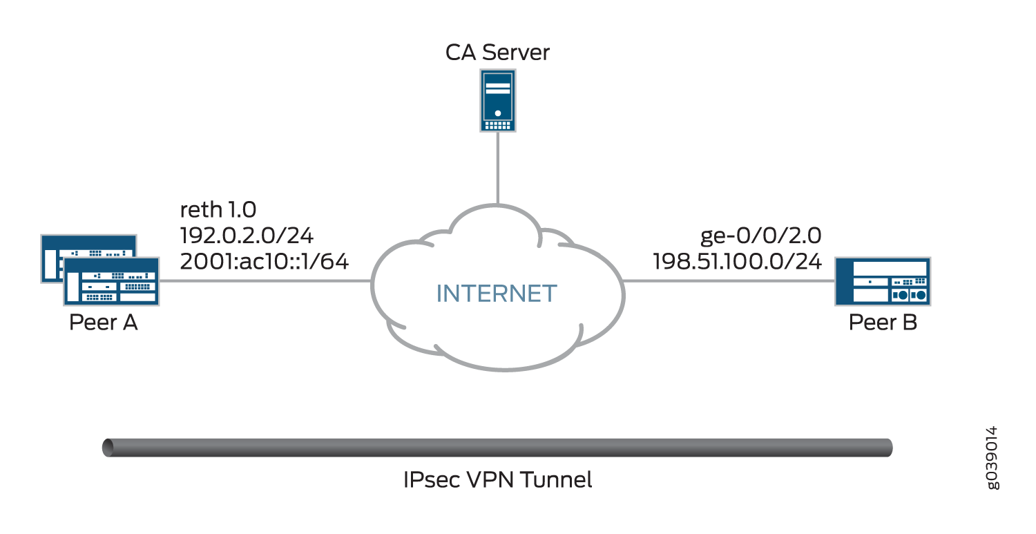
Topology
Figure 1 shows the peer devices that are configured in this example.
Configuration
Configuring Peer A
CLI Quick Configuration
To quickly configure VPN peer A to use OCSP,
copy the following commands, paste them into a text file, remove any
line breaks, change any details necessary to match your network configuration,
copy and paste the commands into the CLI at the [edit]
hierarchy level, and then enter commit from
configuration mode.
set interfaces ge-0/0/3 gigether-options redundant-parent reth1
set interfaces ge-9/0/3 gigether-options redundant-parent reth1
set interfaces lo0 unit 0 family inet address 172.16.1.100/24
set interfaces lo0 redundant-pseudo-interface-options redundancy-group 1
set interfaces reth1 redundant-ether-options redundancy-group 1
set interfaces reth1 unit 0 family inet address 192.0.2.50/24
set interfaces st0 unit 1 family inet address 172.18.1.100/24
set security pki ca-profile OCSP-ROOT ca-identity OCSP-ROOT
set security pki ca-profile OCSP-ROOT enrollment url http://10.1.1.1:8080/scep/OCSP-ROOT/
set security pki ca-profile OCSP-ROOT revocation-check ocsp url http://10.157.88.56:8210/OCSP-ROOT/
set security pki ca-profile OCSP-ROOT revocation-check use-ocsp
set security pki ca-profile OCSP-ROOT revocation-check ocsp disable-responder-revocation-check
set security pki ca-profile OCSP-ROOT revocation-check ocsp connection-failure fallback-crl
set security pki ca-profile OCSP-ROOT revocation-check crl url http://10.1.1.1:8080/crl-as-der/currentcrl-45.crlid=45
set security ike proposal ike_prop authentication-method rsa-signatures
set security ike proposal ike_prop dh-group group2
set security ike proposal ike_prop authentication-algorithm sha1
set security ike proposal ike_prop encryption-algorithm 3des-cbc
set security ike policy ike_policy mode aggressive
set security ike policy ike_policy proposals ike_prop
set security ike policy ike_policy certificate local-certificate localcert1
set security ike gateway jsr_gateway ike-policy ike_policy
set security ike gateway jsr_gateway address 198.51.100.50
set security ike gateway jsr_gateway remote-identity hostname localcert11.example.net
set security ike gateway jsr_gateway external-interface reth1
set security ike gateway jsr_gateway version v2-only
set security ipsec proposal ipsec_prop protocol esp
set security ipsec proposal ipsec_prop authentication-algorithm hmac-sha1-96
set security ipsec proposal ipsec_prop encryption-algorithm 3des-cbc
set security ipsec proposal ipsec_prop lifetime-seconds 1200
set security ipsec proposal ipsec_prop lifetime-kilobytes 150000
set security ipsec policy ipsec_policy perfect-forward-secrecy keys group2
set security ipsec policy ipsec_policy proposals ipsec_prop
set security ipsec vpn test_vpn bind-interface st0.1
set security ipsec vpn test_vpn ike gateway jsr_gateway
set security ipsec vpn test_vpn ike ipsec-policy ipsec_policy
Step-by-Step Procedure
The following example requires you to navigate various levels in the configuration hierarchy. For instructions on how to do that, see Using the CLI Editor in Configuration Mode in the Junos OS CLI User Guide.
To configure VPN peer A to use OCSP:
Configure interfaces.
[edit interfaces]
set ge-0/0/3 gigether-options redundant-parent reth1
set ge-9/0/3 gigether-options redundant-parent reth1
set lo0 unit 0 family inet address 172.16.1.100/24
set  lo0 redundant-pseudo-interface-options redundancy-group 1
set reth1 redundant-ether-options redundancy-group 1
set reth1 unit 0 family inet address 192.0.2.0/24
set st0 unit 1 family inet address 172.18.1.100/24
Configure the CA profile.
[edit security pki ca-profile OCSP-ROOT]
set ca-identity OCSP-ROOT
set enrollment url http://10.1.1.1:8080/scep/OCSP-ROOT/
set revocation-check ocsp url http://10.157.88.56:8210/OCSP-ROOT/
set  revocation-check use-ocsp
set revocation-check ocsp disable-responder-revocation-check
set revocation-check ocsp connection-failure fallback-crl
set revocation-check crl url http://10.1.1.1:8080/crl-as-der/currentcrl-45.crlid=45
Configure Phase 1 options.
[edit security ike proposal ike_prop]
set authentication-method rsa-signatures
set dh-group group2
set authentication-algorithm sha1
set encryption-algorithm 3des-cbc

[edit security ike policy ike_policy]
set mode aggressive
set proposals ike_prop
set certificate local-certificate localcert1

[edit security ike gateway jsr_gateway]
set ike-policy ike_policy
set address 198.51.100.50
set remote-identity hostname localcert11.example.net
set external-interface reth1
set version v2-only
Configure Phase 2 options.
[edit security ipsec proposal ipsec_prop]
set protocol esp
set authentication-algorithm hmac-sha1-96
set encryption-algorithm 3des-cbc
set lifetime-seconds 1200
set lifetime-kilobytes 150000

[edit security ipsec policy ipsec_policy]
set perfect-forward-secrecy keys group2
set proposals ipsec_prop

[edit security ipsec vpn test_vpn]
set bind-interface st0.1
set ike gateway jsr_gateway
set ike ipsec-policy ipsec_policy
Results
From configuration mode, confirm your configuration
by entering the show interfaces, show security pki
ca-profile OCSP-ROOT, show security ike, and show security ipsec commands. If the output does not display
the intended configuration, repeat the configuration instructions
in this example to correct it.
[edit]
user@host# show interfaces
ge-0/0/3 {
    gigether-options {
        redundant-parent reth1;
    }
}
ge-9/0/3 {
    gigether-options {
        redundant-parent reth1;
    }
}
lo0 {
    unit 0 {
        family inet {
            address 172.16.1.100/24;
        }
    }
    redundant-pseudo-interface-options {
        redundancy-group 1;
    }
}
reth1 {
    redundant-ether-options {
        redundancy-group 1;
    }
    unit 0 {
        family inet {
            address 192.0.2.0/24;
        }
    }
}
st0 {
    unit 1 {
        family inet {
            address 172.18.1.100/24;
        }
    }
}
[edit]
user@host# show security pki ca-profile OCSP-ROOT
ca-identity OCSP-ROOT;
enrollment {
    url http://10.1.1.1:8080/scep/OCSP-ROOT/;
}
revocation-check {
    crl {
        url http://10.1.1.1:8080/crl-as-der/currentcrl-45.crlid=45;
    }
    ocsp {
        disable-responder-revocation-check;
        url http://10.157.88.56:8210/OCSP-ROOT/;
    }
    use-ocsp;
}
[edit]
user@host# show security ike
proposal ike_prop {
    authentication-method rsa-signatures;
    dh-group group2;
    authentication-algorithm sha1;
    encryption-algorithm 3des-cbc;
}
policy ike_policy {
    mode aggressive;
    proposals ike_prop;
    certificate {
        local-certificate localcert1;
    }
}
gateway jsr_gateway {
    ike-policy ike_policy;
    address 10.10.2.50;
    remote-identity hostname localcert11.example.net;
    external-interface reth1;
    version v2-only;
}
[edit]
user@host# show security ipsec
proposal ipsec_prop {
    protocol esp;
    authentication-algorithm hmac-sha1-96;
    encryption-algorithm 3des-cbc;
    lifetime-seconds 1200;
    lifetime-kilobytes 150000;
}
policy ipsec_policy {
    perfect-forward-secrecy {
        keys group2;
    }
    proposals ipsec_prop;
}
vpn test_vpn {
    bind-interface st0.1;
    ike {
        gateway jsr_gateway;
        ipsec-policy ipsec_policy;
    }
}
If you are done configuring the device, enter commit from configuration mode.
Configuring Peer B
CLI Quick Configuration
To quickly configure VPN peer B to use OCSP,
copy the following commands, paste them into a text file, remove any
line breaks, change any details necessary to match your network configuration,
copy and paste the commands into the CLI at the [edit]
hierarchy level, and then enter commit from
configuration mode.
set interfaces ge-0/0/2 unit 0 family inet address 198.51.100.0/24
set interfaces lo0 unit 0 family inet address 172.17.1.100/24
set interfaces st0 unit 1 family inet address 172.18.1.1/24
set security pki ca-profile OCSP-ROOT ca-identity OCSP-ROOT
set security pki ca-profile OCSP-ROOT enrollment url http://10.1.1.1:8080/scep/OCSP-ROOT/
set security pki ca-profile OCSP-ROOT revocation-check ocsp url http://10.157.88.56:8210/OCSP-ROOT/
set security pki ca-profile OCSP-ROOT revocation-check use-ocsp
set security pki ca-profile OCSP-ROOT revocation-check ocsp disable-responder-revocation-check
set security pki ca-profile OCSP-ROOT revocation-check ocsp connection-failure fallback-crl
set security pki ca-profile OCSP-ROOT revocation-check crl url http://10.1.1.1:8080/crl-as-der/currentcrl-45.crlid=45
set security ike proposal ike_prop authentication-method rsa-signatures
set security ike proposal ike_prop dh-group group2
set security ike proposal ike_prop authentication-algorithm sha1
set security ike proposal ike_prop encryption-algorithm 3des-cbc
set security ike policy ike_policy mode aggressive
set security ike policy ike_policy proposals ike_prop
set security ike policy ike_policy certificate local-certificate localcert11
set security ike gateway jsr_gateway ike-policy ike_policy
set security ike gateway jsr_gateway address 192.0.2.50
set security ike gateway jsr_gateway local-identity hostname localcert11.example.net
set security ike gateway jsr_gateway external-interface ge-0/0/2.0
set security ike gateway jsr_gateway version v2-only
set security ipsec proposal ipsec_prop protocol esp
set security ipsec proposal ipsec_prop authentication-algorithm hmac-sha1-96
set security ipsec proposal ipsec_prop encryption-algorithm 3des-cbc
set security ipsec proposal ipsec_prop lifetime-seconds 1200
set security ipsec proposal ipsec_prop lifetime-kilobytes 150000
set security ipsec policy ipsec_policy perfect-forward-secrecy keys group2
set security ipsec policy ipsec_policy proposals ipsec_prop
set security ipsec vpn test_vpn bind-interface st0.1
set security ipsec vpn test_vpn ike gateway jsr_gateway
set security ipsec vpn test_vpn ike ipsec-policy ipsec_policy
set security ipsec vpn test_vpn establish-tunnels immediately
Step-by-Step Procedure
The following example requires you to navigate various levels in the configuration hierarchy. For instructions on how to do that, see Using the CLI Editor in Configuration Mode in the Junos OS CLI User Guide.
To configure VPN peer B to use OCSP:
Configure interfaces.
[edit interfaces]
set ge-0/0/2 unit 0 family inet address 198.51.100.0/24
set lo0 unit 0 family inet address 172.17.1.100/24
set st0 unit 1 family inet address 172.18.1.1/24
Configure the CA profile.
[edit security pki ca-profile OCSP-ROOT]
set ca-identity OCSP-ROOT
set enrollment url http://10.1.1.1:8080/scep/OCSP-ROOT/
set revocation-check ocsp url http://10.157.88.56:8210/OCSP-ROOT/
set  revocation-check use-ocsp
set revocation-check ocsp disable-responder-revocation-check
set revocation-check ocsp connection-failure fallback-crl
set revocation-check crl url http://10.1.1.1:8080/crl-as-der/currentcrl-45.crlid=45
Configure Phase 1 options.
[edit security ike proposal ike_prop]
set authentication-method rsa-signatures
set dh-group group2
set authentication-algorithm sha1
set encryption-algorithm 3des-cbc

[edit security ike policy ike_policy]
set mode aggressive
set proposals ike_prop
set certificate local-certificate localcert1

[edit security ike gateway jsr_gateway]
set ike-policy ike_policy
set address 192.0.2.50
set local-identity hostname localcert11.example.net
set external-interface ge-0/0/2.0
set version v2-only
Configure Phase 2 options.
[edit security ipsec proposal ipsec_prop]
set protocol esp
set authentication-algorithm hmac-sha1-96
set encryption-algorithm 3des-cbc
set lifetime-seconds 1200
set lifetime-kilobytes 150000

[edit security ipsec policy ipsec_policy]
set perfect-forward-secrecy keys group2
set proposals ipsec_prop

[edit security ipsec vpn test_vpn]
set bind-interface st0.1
set ike gateway jsr_gateway
set ike ipsec-policy ipsec_policy
set establish-tunnels immediately
Results
From configuration mode, confirm your configuration
by entering the show interfaces, show security pki
ca-profile OCSP-ROOT, show security ike, and show security ipsec commands. If the output does not display
the intended configuration, repeat the configuration instructions
in this example to correct it.
[edit]
user@host# show interfaces
ge-0/0/2 {
    unit 0 {
        family inet {
            address 198.51.100.0/24;
        }
    }
}
lo0 {
    unit 0 {
        family inet {
            address 172.17.1.100/24;
        }
    }
}
st0 {
    unit 1 {
        family inet {
            address 172.18.1.1/24;
        }
    }
}
[edit]
user@host# show security pki ca-profile OCSP-ROOT
ca-identity OCSP-ROOT;
enrollment {
    url http://10.1.1.1:8080/scep/OCSP-ROOT/;
}
revocation-check {
    crl {
        url http://10.1.1.1:8080/crl-as-der/currentcrl-45.crlid=45;
    }
    ocsp {
        disable-responder-revocation-check;
        url http://10.157.88.56:8210/OCSP-ROOT/;
    }
    use-ocsp;
}
[edit]
user@host# show security ike
proposal ike_prop {
    authentication-method rsa-signatures;
    dh-group group2;
    authentication-algorithm sha1;
    encryption-algorithm 3des-cbc;
}
policy ike_policy {
    mode aggressive;
    proposals ike_prop;
    certificate {
        local-certificate localcert11;
    }
}
gateway jsr_gateway {
    ike-policy ike_policy;
    address 192.0.2.50;
    local-identity hostname localcert11.example.net;
    external-interface ge-0/0/2.0;
    version v2-only;
}
[edit]
user@host# show security ipsec
proposal ipsec_prop {
    protocol esp;
    authentication-algorithm hmac-sha1-96;
    encryption-algorithm 3des-cbc;
    lifetime-seconds 1200;
    lifetime-kilobytes 150000;
}
policy ipsec_policy {
    perfect-forward-secrecy {
        keys group2;
    }
    proposals ipsec_prop;
}
vpn test_vpn {
    bind-interface st0.1;
    ike {
        gateway jsr_gateway;
        ipsec-policy ipsec_policy;
    }
    establish-tunnels immediately;
}
If you are done configuring the device, enter commit from configuration mode.
Verification
Confirm that the configuration is working properly.
- Verifying CA Certificates
- Verifying Local Certificates
- Verifying IKE Phase 1 Status
- Verifying IPsec Phase 2 Status
Verifying CA Certificates
Purpose
Verify the validity of a CA certificate on each peer device.
Action
From operational mode, enter the show security
pki ca-certificate ca-profile OCSP-ROOT or show security
pki ca-certificate ca-profile OCSP-ROOT detail command.
user@host> show security pki ca-certificate ca-profile OCSP-ROOT
Certificate identifier: OCSP-ROOT
  Issued to: OCSP-ROOT, Issued by: C = US, O = example, CN = OCSP-ROOT
  Validity:
    Not before: 11-15-2013 22:26 UTC
    Not after: 11-14-2016 22:26 UTC
  Public key algorithm: rsaEncryption(2048 bits)

user@host> show security pki ca-certificate ca-profile OCSP-ROOT detail
Certificate identifier: OCSP-ROOT
  Certificate version: 3
  Serial number: 0000a17f
  Issuer:
    Organization: example, Country: US, Common name: OCSP-ROOT
  Subject:
    Organization: example, Country: US, Common name: OCSP-ROOT
  Subject string:
    C=US, O=example, CN=OCSP-ROOT
  Validity:
    Not before: 11-15-2013 22:26 UTC
    Not after: 11-14-2016 22:26 UTC
  Public key algorithm: rsaEncryption(2048 bits)
    30:82:01:0a:02:82:01:01:00:c6:38:e9:03:69:5e:45:d8:a3:ea:3d
    2e:e3:b8:3f:f0:5b:39:f0:b7:35:64:ed:60:a0:ba:89:28:63:29:e7
    27:82:47:c4:f6:41:53:c8:97:d7:1e:3c:ca:f0:a0:b9:09:0e:3d:f8
    76:5b:10:6f:b5:f8:ef:c5:e8:48:b9:fe:46:a3:c6:ba:b5:05:de:2d
    91:ce:20:12:8f:55:3c:a6:a4:99:bb:91:cf:05:5c:89:d3:a7:dc:a4
    d1:46:f2:dc:36:f3:f0:b5:fd:1d:18:f2:e6:33:d3:38:bb:44:8a:19
    ad:e0:b1:1a:15:c3:56:07:f9:2d:f6:19:f7:cd:80:cf:61:de:58:b8
    a3:f5:e0:d1:a3:3a:19:99:80:b0:63:03:1f:25:05:cc:b2:0c:cd:18
    ef:37:37:46:91:20:04:bc:a3:4a:44:a9:85:3b:50:33:76:45:d9:ba
    26:3a:3b:0d:ff:82:40:36:64:4e:ea:6a:d8:9b:06:ff:3f:e2:c4:a6
    76:ee:8b:58:56:a6:09:d3:4e:08:b0:64:60:75:f3:e2:06:91:64:73
    d2:78:e9:7a:cb:8c:57:0e:d1:9a:6d:3a:4a:9e:5b:d9:e4:a2:ef:31
    5d:2b:2b:53:ab:a1:ad:45:49:fd:a5:e0:8b:4e:0b:71:52:ca:6b:fa
    8b:0e:2c:7c:7b:02:03:01:00:01
  Signature algorithm: sha1WithRSAEncryption
  Distribution CRL:
    http://10.1.1.1:8080/crl-as-der/currentcrl-45.crl?id=45
  Authority Information Access OCSP:
    http://10.1.1.1:8090/OCSP-ROOT/
  Use for key: CRL signing, Certificate signing, Key encipherment, Digital signature
  Fingerprint:
    ed:ce:ec:13:1a:d2:ab:0a:76:e5:26:6d:2c:29:5d:49:90:57:f9:41 (sha1)
    af:87:07:69:f0:3e:f7:c6:b8:2c:f8:df:0b:ae:b0:28 (md5)
In this example, IP addresses are used in the URLs in the CA profile configuration. If IP addresses are not used with CA-issued certificates or CA certificates, DNS must be configured in the device’s configuration. DNS must be able to resolve the host in the distribution CRL and in the CA URL in the CA profile configuration. Additionally, you must have network reachability to the same host to receive revocation checks.
Meaning
The output shows the details and validity of CA certificate on each peer as follows:
C—Country.O—Organization.CN—Common name.Not before—Begin date of validity.Not after—End date of validity.
Verifying Local Certificates
Purpose
Verify the validity of a local certificate on each peer device.
Action
From operational mode, enter the show security
pki local-certificate certificate-id localcert1 detail command.
user@host> show security pki local-certificate certificate-id localcert1 detail
Certificate identifier: localcert1
  Certificate version: 3
  Serial number: 013e3f1d
  Issuer:
    Organization: example, Country: US, Common name: OCSP-ROOT
  Subject:
    Organization: example, Organizational unit: example, State: california1, Locality: sunnyvale1, Common name: localcert1, Domain component: domain_component1
  Subject string:
    DC=domain_component1, CN=localcert1, OU=example, O=example, L=sunnyvale1, ST=california1, C=us1
  Alternate subject: "localcert1@example.net", localcert1.example.net, 10.10.1.50
  Validity:
    Not before: 01-28-2014 22:23 UTC
    Not after: 03-29-2014 22:53 UTC
  Public key algorithm: rsaEncryption(1024 bits)
    30:81:89:02:81:81:00:a6:df:c1:57:59:f8:4d:0f:c4:a8:96:25:97
    03:c4:a0:fb:df:d5:f3:d5:56:b6:5a:26:65:b8:1a:ec:be:f6:c6:5f
    b3:d7:d3:59:39:48:52:4a:e3:1b:e4:e0:6d:24:c3:c1:50:8c:55:3b
    c0:c1:29:a0:45:29:8e:ec:3e:52:2f:84:b3:e8:89:9a:0f:8b:7d:e8
    90:4b:c1:28:48:95:b3:aa:11:ab:b4:8c:a8:80:ce:90:07:2a:13:a2
    2f:84:44:92:3b:be:7d:39:5b:2f:9a:4c:7a:2f:2d:31:8b:12:6d:52
    34:7d:6b:e4:69:7e:f3:86:55:e2:89:31:98:c9:15:02:03:01:00:01
  Signature algorithm: sha1WithRSAEncryption
  Distribution CRL:
    http://10.1.1.1:8080/crl-as-der/currentcrl-45.crl?id=45
  Authority Information Access OCSP:
    http://10.1.1.1/:8090/OCSP-ROOT/
  Fingerprint:
    00:c6:56:64:ad:e3:ce:8e:26:6b:df:17:1e:de:fc:14:a4:bb:8c:e4 (sha1)
    7f:43:c6:ed:e4:b3:7a:4f:9a:8c:0b:61:95:01:c9:52 (md5)
  Auto-re-enrollment:
    Status: Disabled
    Next trigger time: Timer not started
Meaning
The output shows the details and validity of a local certificate on each peer as follows:
DC—Domain component.CN—Common name.OU—Organizational unit.O—Organization.L—LocalityST—State.C—Country.Not before—Begin date of validity.Not after—End date of validity.
Verifying IKE Phase 1 Status
Purpose
Verify the IKE Phase 1 status on each peer device.
Action
From operational mode, enter the show security
ike security-associations command.
user@host> show security ike security-associations
Index   State  Initiator cookie  Responder cookie  Mode           Remote Address
6534660 UP     3e62e05abd6a703f  c552b238e8a26668  IKEv2          198.51.100.50
From operational mode, enter the show security ike security-associations
detail command.
user@host> show security ike security-associations detail
IKE peer 198.51.100.50, Index 6534660, Gateway Name: jsr_gateway
  Role: Responder, State: UP
  Initiator cookie: 3e62e05abd6a703f, Responder cookie: c552b238e8a26668
  Exchange type: IKEv2, Authentication method: RSA-signatures
  Local: 192.0.2.50:500, Remote: 198.51.100.50:500
  Lifetime: Expires in 26906 seconds
  Peer ike-id: localcert11.example.net
  Xauth assigned IP: 0.0.0.0
  Algorithms:
   Authentication        : hmac-sha1-96
   Encryption            : 3des-cbc
   Pseudo random function: hmac-sha1
   Diffie-Hellman group  : DH-group-2
  Traffic statistics:
   Input  bytes  :                 2152
   Output bytes  :                 2097
   Input  packets:                    4
   Output packets:                    4
  Flags: IKE SA is created
  IPSec security associations: 4 created, 0 deleted
  Phase 2 negotiations in progress: 0

    Negotiation type: Quick mode, Role: Responder, Message ID: 0
    Local: 192.0.2.50:500, Remote: 198.51.100.50:500
    Local identity: 192.0.2.50
    Remote identity: localcert11.example.net
    Flags: IKE SA is created
Meaning
The flags field in the output shows that,
IKE security association is created.
Verifying IPsec Phase 2 Status
Purpose
Verify the IPsec Phase 2 status on each peer device.
Action
From operational mode, enter the show security
ipsec security-associations command.
user@host> show security ipsec security-associations
  Total active tunnels: 1
  ID    Algorithm       SPI      Life:sec/kb  Mon lsys Port  Gateway
  <131073 ESP:3des/sha1 9d1066e2 252/   150000 -   root 500   198.51.100.50
  >131073 ESP:3des/sha1 82079c2c 252/   150000 -   root 500   198.51.100.50
From operational mode, enter the show security ipsec security-associations
detail command.
user@host> show security ipsec security-associations detail
  ID: 131073 Virtual-system: root, VPN Name: test_vpn
  Local Gateway: 192.0.2.50, Remote Gateway: 198.51.100.50
  Local Identity: ipv4_subnet(any:0,[0..7]=0.0.0.0/0)
  Remote Identity: ipv4_subnet(any:0,[0..7]=0.0.0.0/0)
  Version: IKEv2
    DF-bit: clear
    Bind-interface: st0.1

  Port: 500, Nego#: 2, Fail#: 0, Def-Del#: 0 Flag: 0x600a29
  Last Tunnel Down Reason: Delete payload received
    Direction: inbound, SPI: 9d1066e2, AUX-SPI: 0
                              , VPN Monitoring: -
    Hard lifetime: Expires in 249 seconds
    Lifesize Remaining:  150000 kilobytes
    Soft lifetime: Expires in 10 seconds
    Mode: Tunnel(0 0), Type: dynamic, State: installed
    Protocol: ESP, Authentication: hmac-sha1-96, Encryption: 3des-cbc
    Anti-replay service: counter-based enabled, Replay window size: 64

    Direction: outbound, SPI: 82079c2c, AUX-SPI: 0
                              , VPN Monitoring: -
    Hard lifetime: Expires in 249 seconds
    Lifesize Remaining:  150000 kilobytes
    Soft lifetime: Expires in 10 seconds
    Mode: Tunnel(0 0), Type: dynamic, State: installed
    Protocol: ESP, Authentication: hmac-sha1-96, Encryption: 3des-cbc
    Anti-replay service: counter-based enabled, Replay window size: 64
Meaning
The output shows the ipsec security associations details.