Five-Level and Four-Level Heterogeneous Networks
CoS Node Shaping in Four-Level and Five-Level Heterogeneous Networks
A heterogeneous subscriber access model has the following characteristics:
-
It includes both residential subscribers and business subscribers. Both subscriber types are typically PPPoE subscribers.
-
The access technologies can be conventional or shared media, or both. Shared media access includes bonded copper connections through a DPU-C or fiber connections through a DPU-P. DPU-C and DPU-P are distribution units for the respective media type. Conventional access networks do not include either a DPU-C or DPU-P.
-
Traffic shaping depends on hierarchical CoS. The network can use a four-level scheduler hierarchy, a five-level scheduler hierarchy, or both.
Figure 1 summarizes how CoS shapes key nodes in the five-level scheduler hierarchy. Shaping is based either on the adjusted rates from the DSL and PON TLVs or on traffic control profiles in the dynamic client profile configuration. A CoS adjustment control profile specifies the source of the shaping rate applied to a given node.
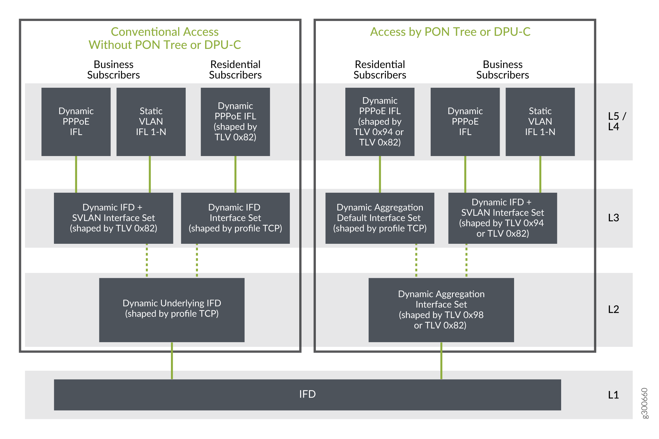
The following lists describe the CoS scheduler nodes by access type and subscriber type for the five-level hierarchy in Figure 1.
For conventional access, residential subscribers:
-
Level 1 node—Corresponds to the access-facing physical interface.
-
Level 2 node—Corresponds to a dynamic interface set that conserves L2 nodes. This parent interface set is based on the underlying physical interface. The name is derived from the predefined variable, $junos-phy-ifd-underlying-intf-set-name, by appending “-underlying”. Traffic shaping is determined by a traffic control profile specified in the dynamic client profile.
-
Level 3 node—Corresponds to a dynamic interface set that conserves Level 3 nodes. This child interface set is based on the physical interface. The name is derived from the predefined variable, $junos-phy-ifd-intf-set-name. Traffic shaping is determined by a traffic control profile specified in the dynamic client profile.
-
Level 4 node—Corresponds to the subscriber’s PPPoE session logical interface. Traffic shaping is determined by the Actual-Data-Rate-Downstream TLV (0x82).
-
Level 5 node—Corresponds to the scheduling queue for the subscriber.
For conventional access, business subscribers:
-
Level 1 node—Corresponds to the access-facing physical interface.
-
Level 2 node—Corresponds to a dynamic interface set that conserves L2 nodes. This parent interface set is based on the underlying physical interface. The name is derived from the predefined variable, $junos-phy-ifd-underlying-intf-set-name by appending “-underlying”. Traffic shaping is determined by a traffic control profile specified in the dynamic client profile.
-
Level 3 node—Corresponds to a dynamic interface set that conserves L3 nodes. This child interface set is based on the physical interface and VLAN tag. The set name is derived in one of two ways:
-
If configured, it is provided by the Qos-Set-Name VSA (26–4874–130) in the Access-Accept from the RADIUS server.
-
It is created from the $junos-phy-ifd-interface-set-name predefined variable by appending the SVLAN tag to the value.
Traffic shaping is determined by the Actual-Data-Rate-Downstream TLV (0x82).
-
-
Level 4 node—Corresponds to the subscriber’s dynamic PPPoE session logical interface or static VLAN logical interface.
-
Level 5 node—Corresponds to the scheduling queue for the subscriber.
For shared-media access, residential subscribers:
-
Level 1 node—Corresponds to the access-facing physical interface.
-
Level 2 node—Corresponds to a dynamic aggregation interface set that conserves L2 nodes. This parent interface set is based on the backhaul identifier from Access-Aggregation-Circuit-Id-ASCII TLV 0x03, which represents the PON tree connection. The name is derived from the predefined-variable, $junos-aggregation-interface-set-name. Traffic shaping is determined by the Actual-Data-Rate-Downstream TLV (0x82) for bonded copper connections and by the PON-Tree-Maximum-Data-Rate-Downstream TLV (0x98) for PON tree connections.
-
Level 3 node—Corresponds to a dynamic aggregation interface set that conserves L3 nodes. This child interface set is based on the backhaul identifier from the Access-Aggregation-Circuit-Id-ASCII TLV (0x03), which represents the PON tree connection. The name is derived from the predefined variable, $junos-aggregation-interface-set-name by appending “-default”. Traffic shaping is determined by a traffic control profile specified in the dynamic client profile.
-
Level 4 node—Corresponds to the subscriber’s PPPoE session logical interface. Traffic shaping is determined by the Actual-Data-Rate-Downstream TLV (0x82) for bonded copper connections and by the ONT/ONU-Peak-Data-Rate-Downstream TLV (0x94) for PON tree connections.
-
Level 5 node—Corresponds to the scheduling queue for the subscriber.
For shared-media access, business subscribers:
-
Level 1 node—Corresponds to the access-facing physical interface.
-
Level 2 node—Corresponds to a dynamic aggregation interface set that conserves L2 nodes. This parent interface set is based on the backhaul identifier from the Access-Aggregation-Circuit-Id-ASCII TLV (0x03), which represents the PON tree connection. The name is derived from the predefined-variable, $junos-aggregation-interface-set-name. Traffic shaping is determined by the Actual-Data-Rate-Downstream TLV (0x82) for bonded copper connections and by the PON-Tree-Maximum-Data-Rate-Downstream TLV (0x98) for PON tree connections.
-
Level 3 node—Corresponds to a dynamic interface set that conserves L3 nodes. This child interface set is based on the physical interface and VLAN tag. The set name is derived in one of two ways:
-
If configured, it is provided by the Qos-Set-Name VSA (26–4874–130) in the Access-Accept from the RADIUS server.
-
It is created from the $junos-phy-ifd-interface-set-name predefined variable by appending the SVLAN tag to the value.
Traffic shaping is determined by the Actual-Data-Rate-Downstream TLV (0x82) for bonded copper connections and by the ONT/ONU-Peak-Data-Rate-Downstream TLV (0x94) for PON tree connections.
-
-
Level 4 node—Corresponds to the subscriber’s dynamic PPPoE session logical interface or static VLAN logical interface.
-
Level 5 node—Corresponds to the scheduling queue for the subscriber.
Figure 2 summarizes how CoS shapes key nodes in the four-level scheduler hierarchy. Shaping is based either on the adjusted rates resulting from the DSL and PON TLVs or on traffic control profiles in the dynamic client profile configuration. A CoS adjustment control profile specifies the source of the shaping rate applied to a given node.
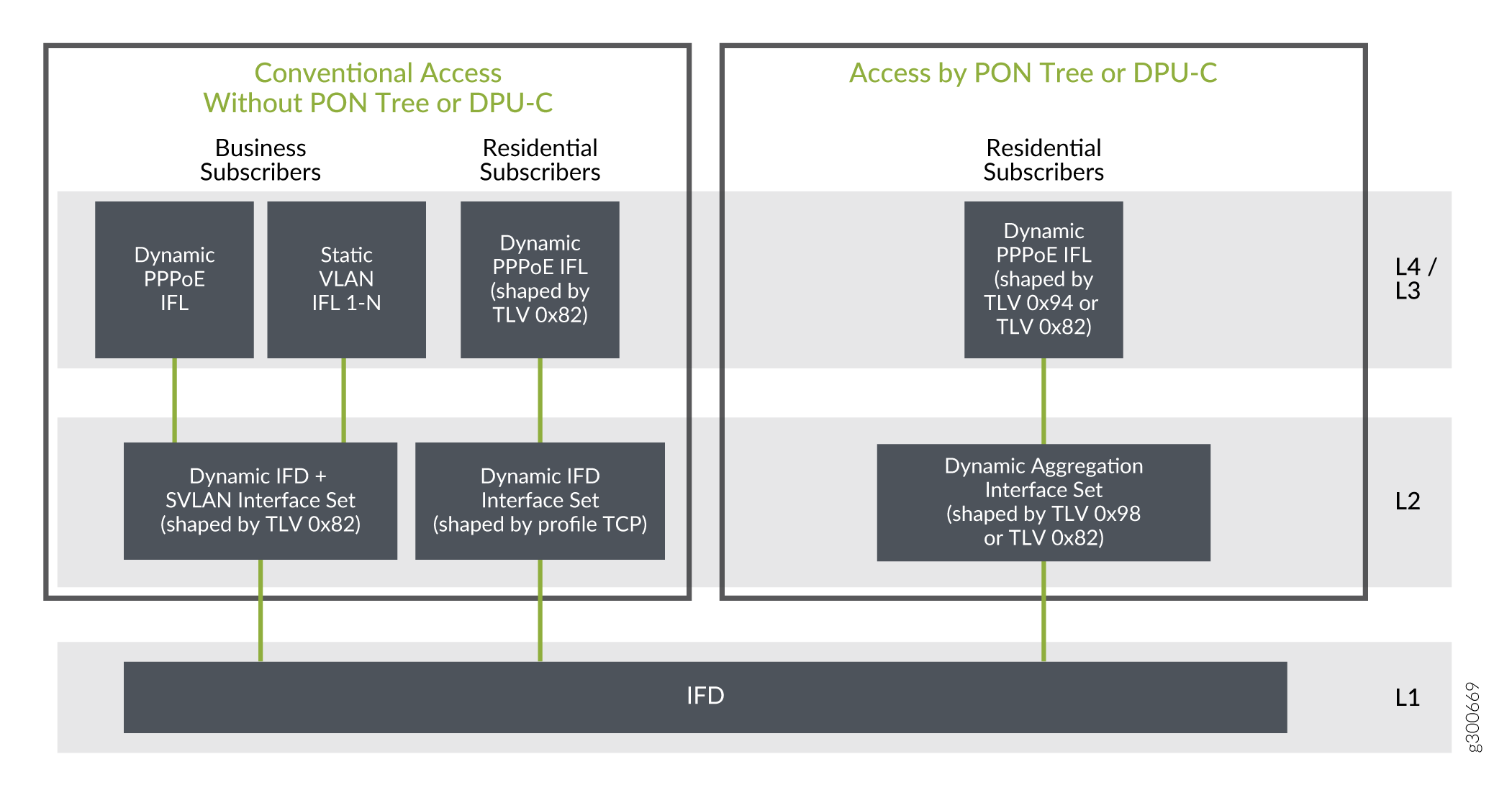
The following lists describe the CoS scheduler nodes by access type and subscriber type for the four-level hierarchy in Figure 2.
For conventional access, residential subscribers:
-
Level 1 node—Corresponds to the access-facing physical interface.
-
Level 2 node—Corresponds to a dynamic interface set that conserves Level 2 nodes. This interface set is based on the physical interface. The name is derived from the predefined variable, $junos-phy-ifd-intf-set-name. Traffic shaping is determined by a traffic control profile specified in the dynamic client profile.
-
Level 3 node—Corresponds to the subscriber’s PPPoE session logical interface. Traffic shaping is determined by the Actual-Data-Rate-Downstream TLV (0x82).
-
Level 4 node—Corresponds to the scheduling queue for the subscriber.
For conventional access, business subscribers:
-
Level 1 node—Corresponds to the access-facing physical interface.
-
Level 2 node—Corresponds to a dynamic interface set that conserves L2 nodes. This interface set is based on the physical interface and VLAN tag. The set name is derived in one of two ways:
-
If configured, it is provided by the Qos-Set-Name VSA (26–4874–130) in the Access-Accept from the RADIUS server.
-
It is created from the $junos-phy-ifd-interface-set-name predefined variable by appending the SVLAN tag to the value.
Traffic shaping is determined by the Actual-Data-Rate-Downstream TLV (0x82).
-
-
Level 3 node—Corresponds to the subscriber’s dynamic PPPoE session logical interface or static VLAN logical interface.
-
Level 4 node—Corresponds to the scheduling queue for the subscriber.
For shared-media access, residential subscribers:
-
Level 1 node—Corresponds to the access-facing physical interface.
-
Level 2 node—Corresponds to a dynamic aggregation interface set that conserves Level 2 nodes. This interface set is based on the backhaul identifier from the Access-Aggregation-Circuit-Id-ASCII TLV (0x03), which represents the PON tree connection. The name is derived from the predefined-variable, $junos-aggregation-interface-set-name. Traffic shaping is determined by the Actual-Data-Rate-Downstream TLV (0x82) for bonded copper connections and by the PON-Tree-Maximum-Data-Rate-Downstream TLV (0x98) for PON tree connections.
-
Level 3 node—Corresponds to the subscriber’s PPPoE session logical interface. Traffic shaping is determined by the Actual-Data-Rate-Downstream TLV (0x82) for bonded copper connections and by the ONT/ONU-Peak-Data-Rate-Downstream TLV (0x94) for PON tree connections.
-
Level 4 node—Corresponds to the scheduling queue for the subscriber.
Business subscribers are not supported in a four-level, shared-media access network.
CuTTB Use Case Topology and CoS Hierarchy
Figure 3 shows a heterogeneous CuTTB topology that includes both shared -media (bonded copper through a DPU-C) and conventional, (nonbonded copper) access for PPPoE subscribers.
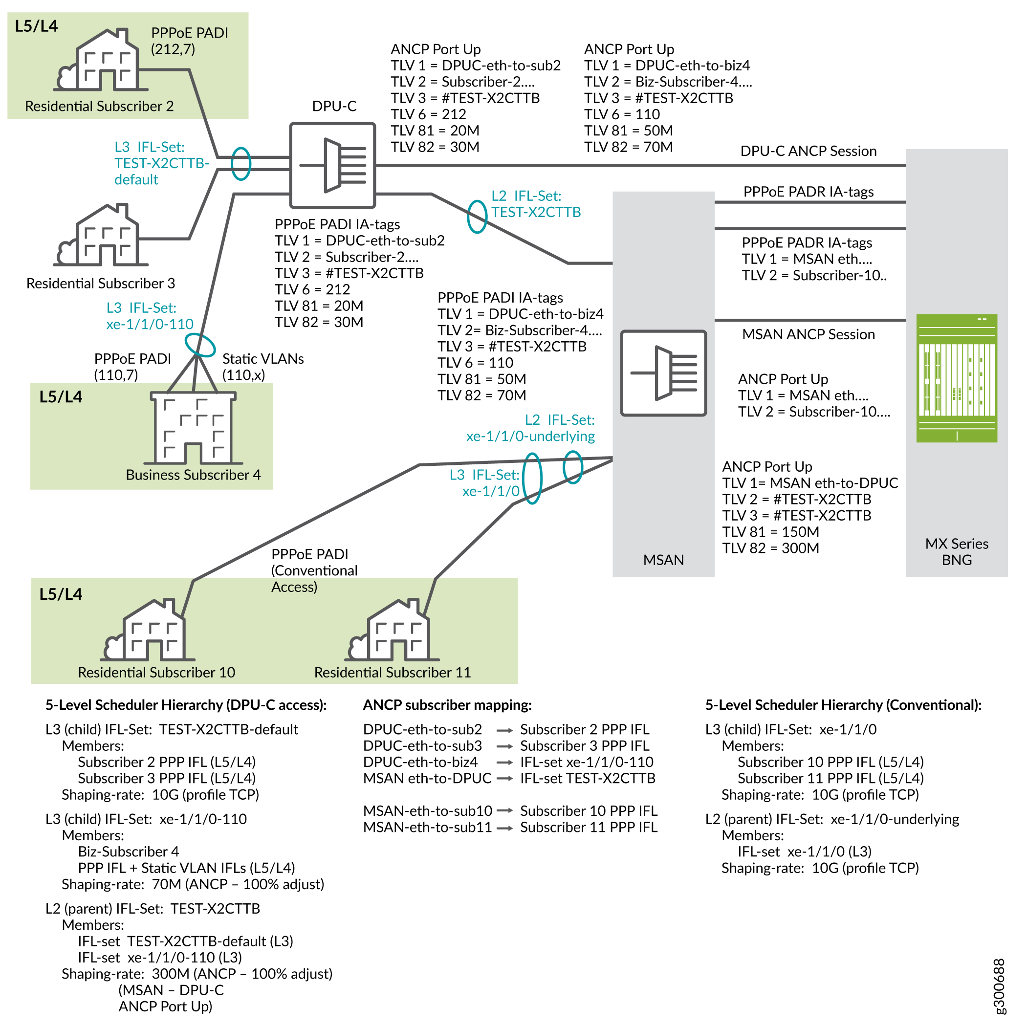
This topology has the following subscribers:
Two residential subscribers, 2 and 3, and a business subscriber, 4, have a shared-media access to the network through a DPU-C to the MSAN and then to the BNG.
Two residential subscribers, 10 and 11, have conventional access to the network through an MSAN to the BNG.
Residential subscriber 3 is not currently logged in.
When residential subscriber 2 and business subscriber 4 log in:
PPPoE sends a PADI message to the DPU-C that includes the outer VLAN tag for each.
The DPU-C sends an ANCP Port Up message to the BNG for each subscriber. ANCP TLVs in the message identify the access line, the subscriber, the ASCII identifier for the access line, the VLAN outer tag as the binary identifier for the access line, the upstream rate, and the downstream rate.
The ASCII identifier (TLV 0x03) begins with the # character, signifying that the remainder of the value identifies the backhaul (bonded copper, shared media) line. TLV 0x03 is the same for both subscribers, because they connect through the same DPU-C.
The DPU-C sends a PADI message for each subscriber to the MSAN. The PADI conveys the PPPoE-IA tags that identify the same attributes as the ANCP TLVs.
The MSAN sends a PADR message with the PPPoE tags to the BNG. The MSAN also opens an ANCP session to the BNG by sending an ANCP Port Up message for the MSAN-to-DPU-C connection. The rates in TLVs 0x81 and 0x82 are the values for the MSAN-to-DPU-C line, represented by the L2 interface set. In other words, these are the rates for the bonded copper line itself rather than the subscriber access lines. TLV 0x03 value is also reported in TLV 0x02 to indicate the bonded copper line.
When residential subscribers 10 and 11 log in:
PPPoE sends a PADI message for each subscriber to the MSAN. The PADI conveys the PPPoE-IA tags for the individual subscriber access lines.
The MSAN sends a PADR message with the PPPoE tags for each subscriber line to the BNG.
The MSAN also sends an ANCP Port Up message to the BNG for each subscriber. ANCP TLVs in the message identify the access line, the subscriber, the ASCII identifier for the access line, the VLAN outer tag as the binary identifier for the access line, the upstream rate, and the downstream rate.
Because these subscribers use conventional access rather than shared-media access through the DPU-C, the ASCII identifier (TLV 0x03) does not begin with the # character. In this case, the value is just the ASCII equivalent of the binary value conveyed in TLV 0x06.
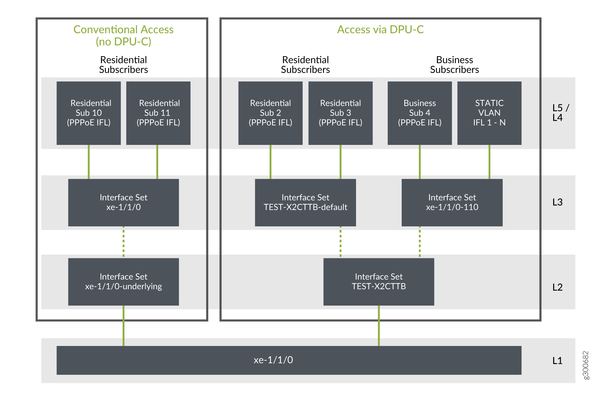
Figure 4 shows the five-level CoS hierarchy that corresponds to the CuTTB topology in Figure 3.
The following stanzas are part of the use case configuration
that creates the Level 2 and Level 3 interface sets. The stacked-interface-set statement sets the Level 2 interface set to the $junos-aggregation-interface-set-name
predefined variable. The stanza also specifies the Level 3 interface
set as $junos-interface-set-name. It establishes the Level 2 set as
the parent of the Level 3 set.
dynamic-profiles test-prof
    interfaces {
        stacked-interface-set {
            interface-set "$junos-aggregation-interface-set-name" {
                interface-set $junos-interface-set-name;
            }
        }
    }
}
The predefined-variable-defaults stanza uses variable
expressions that set conditions to establish the names of the Level
2 and Level 3 interface sets. The default values are used only when
RADIUS does not supply values for $junos-aggregation-interface-set-name
and $junos-interface-set-name.
dynamic-profiles test-prof
    predefined-variable-defaults {
        aggregation-interface-set-name equals "$junos-phy-ifd-underlying-intf-set-name";
        interface-set-name equals "ifZero($junos-default-interface-set-name, $junos-phy-ifd-interface-set-name)";
        default-interface-set-name equals "ifZero($junos-interface-set-name, ifNotZero($junos-aggregation-interface-set-name, $junos-aggregation-interface-set-name##'-default'))";
    }
}
The following list describes the hierarchical CoS scheduler nodes for the CuTTB topology. It explains how the names of the interface sets are derived from predefined variables.
Level 1 corresponds to the access-facing physical interface for all subscribers, xe-1/1/0.
Level 2 corresponds to a parent interface set that has child interface sets as its members. The name of the interface set is supplied by the $junos-aggregation-interface-set-name predefined variable in the dynamic profile.
TEST-X2CTTB is the Level 2 interface set for all shared-media access subscribers. Its members are the Level 3 interface sets for residential subscribers 2 and 3 and for business subscriber 4.
TLV 0x03 includes the # character, which identifies the line as shared. $junos-aggregation-interface-set-name takes the value of TLV 0x03.
xe-1/1/0-underlying is the Level 2 interface set for conventional access. Its member is the Level 3 interface set for residential subscribers 10 and 11.
TLV 0x03 does not include the # character and so does not identify a shared line. $junos-aggregation-interface-set-name is dynamically taken from $junos-phy-ifd-underlying-intf-set-name. The value of $junos-phy-ifd-underlying-intf-set-name is simply the physical interface name with a suffix of “-underlying”.
Level 3 corresponds to a child interface set that has subscriber logical interfaces as its members. The name of the interface set is supplied by the $junos-interface-set-name predefined variable in the dynamic profile.
TEST-X2CTTB-default is the Level 3 interface set for residential subscribers 2 and 3. These subscribers were identified as residential because the RADIUS server did not return VSA 26-4874-130, QoS-Set-Name. TLV 0x03 includes the # character, which identifies the line as shared. $junos-interface-set-name is set to the value of $junos-aggregation-interface-set-name with a suffix of “default”.
xe-1/1/0-110 is the Level 3 interface set for business subscriber 4. This subscriber was identified as business because the RADIUS server returned VSA 26-4874-130. TLV 0x03 includes the # character, which identifies the line as shared. $junos-interface-set-name is set to the value of VSA 26-4874-130. The VSA value is a concatenation of the physical interface name ($junos-phy-ifd-intf-set-name) and the outer VLAN tag.
xe-1/1/0 is the Level 3 interface set for residential subscribers 10 and 11, which use conventional access. These subscribers were identified as residential because the RADIUS server did not return VSA 26-4874-130. $junos-interface-set-name is set to the value of $junos-phy-ifd-intf-set-name.
Level 4 corresponds to the logical interface for individual subscribers. This includes PPPoE logical interfaces for residential and business subscribers, as well as static VLAN logical interfaces for business subscribers.
Level 5 corresponds to the scheduling queue for each subscriber, regardless of subscriber type or access type. One or more queues are present per subscriber to provide subscriber services.
FTTB/FTTH Use Case Topology and CoS Hierarchy
Figure 5 shows a heterogeneous FTTB/FTTH topology that includes both shared -media (PON through a DPU-P) and conventional, (directly connected) access for PPPoE subscribers.
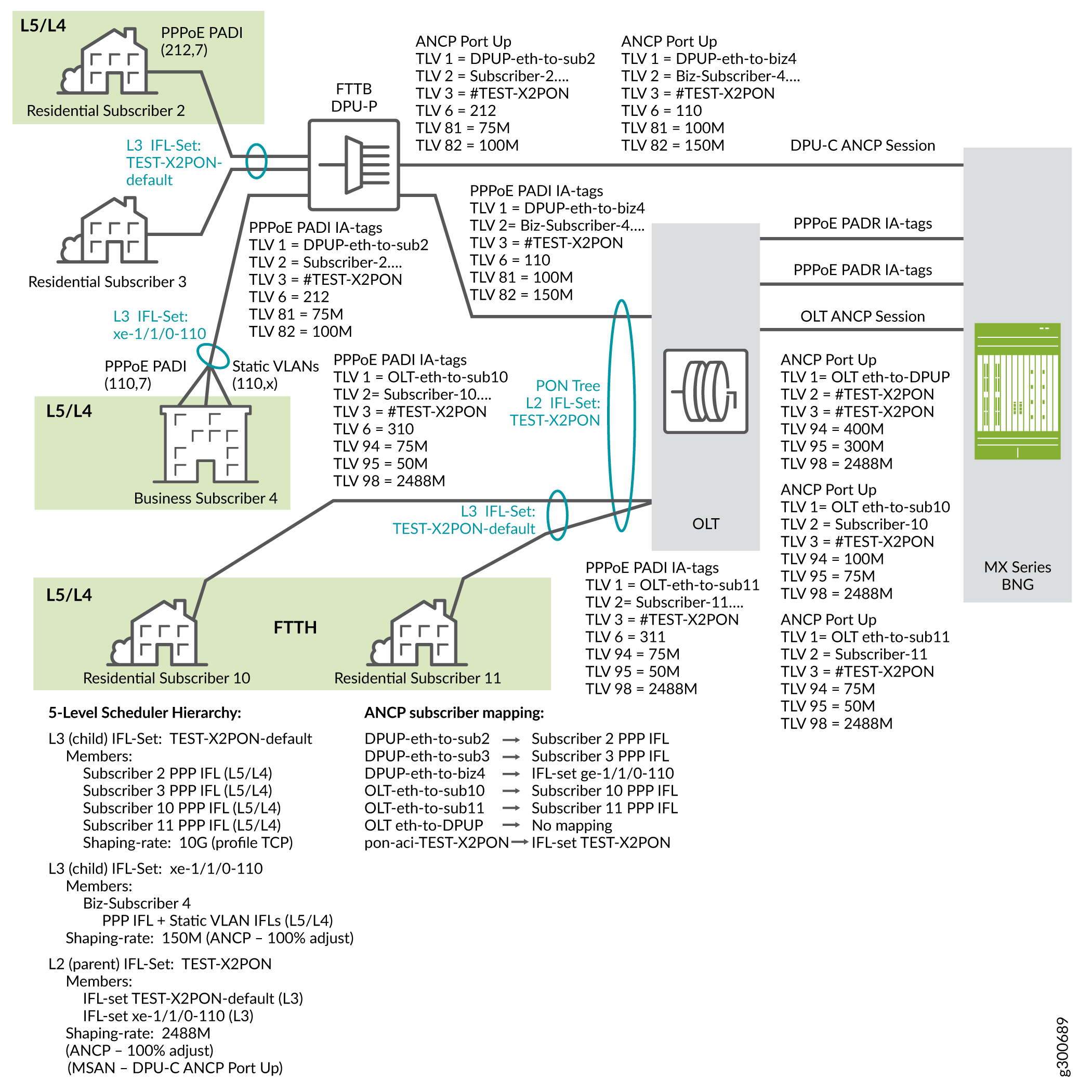
This topology has the following subscribers:
Two residential subscribers, 2 and 3, and a business subscriber, 4, have a shared-media access to the network through a DPU-P to the OLT and then to the BNG. These are FTTB subscribers.
Two residential subscribers, 10 and 11, have conventional access to the network through the same OLT to the BNG. These are FTTH subscribers.
All the FTTB and FTTH subscribers connect to the BNG by means of the same PON tree at the OLT.
Residential subscriber 3 is not currently logged in.
When residential subscriber 2 and business subscriber 4 log in:
PPPoE sends a PADI message to the DPU-P that includes the outer VLAN tag for each.
The DPU-P sends an ANCP Port Up message to the BNG for each subscriber. ANCP TLVs in the message identify the access line, the subscriber, the ASCII identifier for the access line, the VLAN outer tag as the binary identifier for the access line, the upstream rate, and the downstream rate.
The ASCII identifier (TLV 0x03) begins with the # character, signifying that the remainder of the value identifies the backhaul (PON tree) line. TLV 0x03 is the same for both subscribers, because they connect through the same PON tree.
The DPU-P sends a PADI message for each subscriber to the OLT. The PADI conveys the PPPoE-IA tags that identify the same attributes as the ANCP TLVs.
The OLT sends a PADR message with the PPPoE tags to the BNG. The OLT also opens an ANCP session to the BNG by sending an ANCP Port Up message for the OLT-to-DPU-P connection. The rates in TLVs 0x81 and 0x82 are the values for the OLT-to-DPU-P line, represented by the L2 interface set. In other words, these are the rates for the PON tree itself rather than the subscriber access lines. Although this use case example shows that TLV 0x03 value is also reported in TLV 0x02 to indicate the PON tree line, this is not a requirement for PON networks.
Note:The FTTB portion of this network connects G.fast DSL subscribers to the PON tree shared media backhaul. Consequently the DPU-P reports DSL TLVs for these subscribers rather than PON TLVs.
When residential subscribers 10 and 11 log in:
PPPoE sends a PADI message for each subscriber to the OLT. The PADI conveys the PPPoE-IA tags for the individual subscriber access lines.
The OLT sends a PADR message with the PPPoE tags for each subscriber line to the BNG.
The OLT also sends an ANCP Port Up message to the BNG for each subscriber. ANCP TLVs in the message identify the access line, the subscriber, the ASCII identifier for the access line, the VLAN outer tag as the binary identifier for the access line, the upstream rate, and the downstream rate.
The ASCII identifier (TLV 0x03) begins with the # character, signifying that the remainder of the value identifies the backhaul (fiber PON tree, shared media) line. TLV 0x03 is the same for both subscribers, because they connect through the same DPU-P.
Because subscribers 10 and 11 connect to the same PON tree as the FTTB subscribers, the ASCII identifier (TLV 0x03) also begins with the # character, signifying that the remainder of the value identifies the backhaul (fiber PON tree, shared media) line. TLV 0x03 is the same for both subscribers.
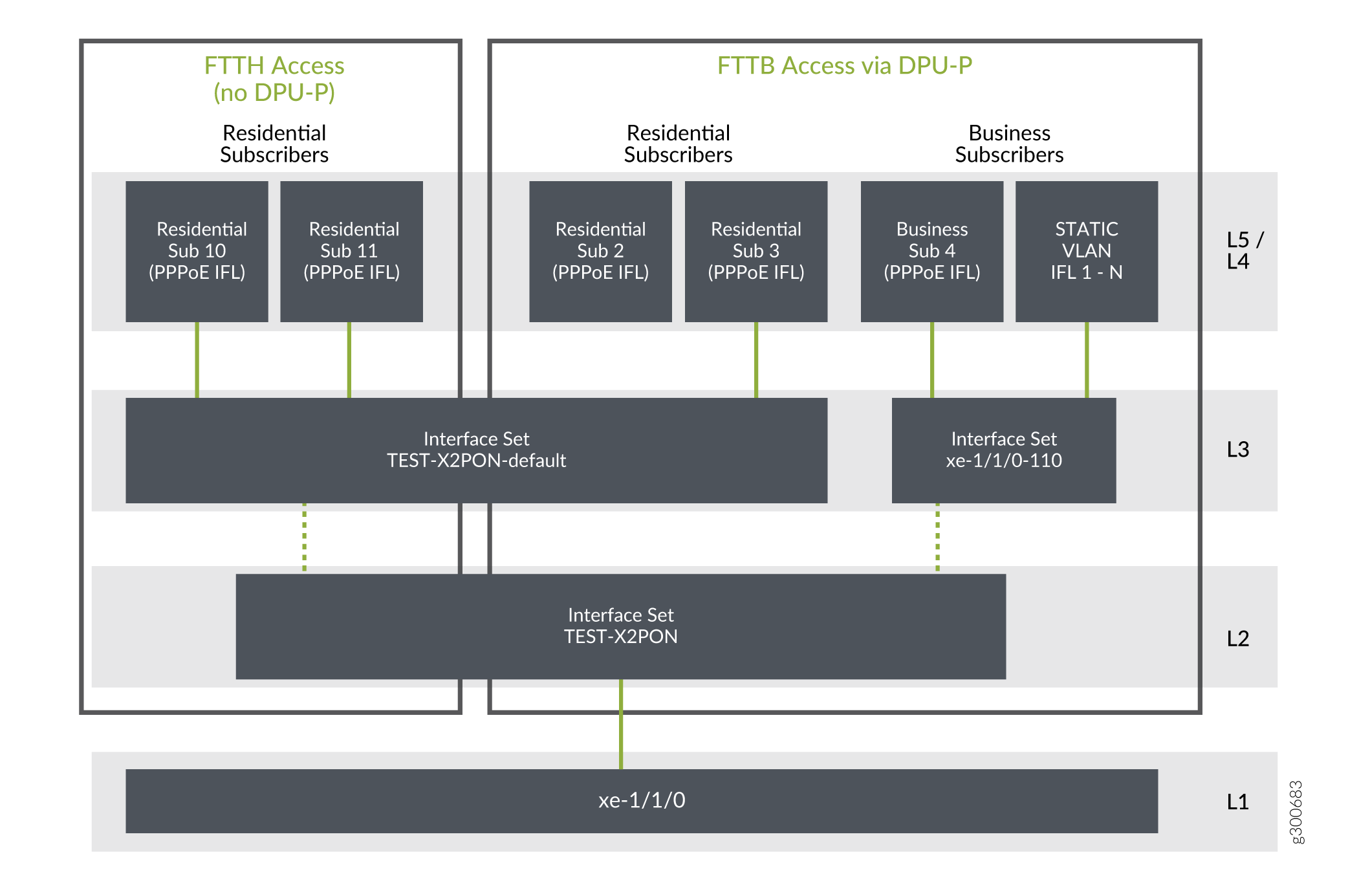
Figure 6 shows the five-level CoS hierarchy that corresponds to the FTTB/FTTH topology in Figure 5.
The following stanzas are part of the use case configuration
that creates the Level 2 and Level 3 interface sets. The stacked-interface-set statement sets the Level 2 interface set to the $junos-aggregation-interface-set-name
predefined variable. The stanza also specifies the Level 3 interface
set as $junos-interface-set-name. It establishes the Level 2 set as
the parent of the Level 3 set.
dynamic-profiles test-prof
    interfaces {
        stacked-interface-set {
            interface-set "$junos-aggregation-interface-set-name" {
                interface-set $junos-interface-set-name;
            }
        }
    }
}
The predefined-variable-defaults stanza uses variable
expressions that set conditions to establish the names of the Level
2 and Level 3 interface sets. The default values are used only when
RADIUS does not supply values for $junos-aggregation-interface-set-name
and $junos-interface-set-name.
dynamic-profiles test-prof
    predefined-variable-defaults {
        aggregation-interface-set-name equals "$junos-phy-ifd-underlying-intf-set-name";
        interface-set-name equals "ifZero($junos-default-interface-set-name, $junos-phy-ifd-interface-set-name)";
        default-interface-set-name equals "ifZero($junos-interface-set-name, ifNotZero($junos-aggregation-interface-set-name, $junos-aggregation-interface-set-name##'-default'))";
    }
}
The following list describes the hierarchical CoS scheduler nodes for the FTTB/FTTH topology. It explains how the names of the interface sets are derived from predefined variables.
Level 1 corresponds to the access-facing physical interface for all subscribers, xe-1/1/0.
Level 2 corresponds to a parent interface set that has child interface sets as its members. The name of the interface set is supplied by the $junos-aggregation-interface-set-name predefined variable in the dynamic profile.
TEST-X2PON is the Level 2 interface set for all PON subscribers, both conventional access and DPU-P access. Its members are the Level 3 interface set for the FTTB/FTTH residential subscribers and the Level 3 interface set for business subscriber 4. TLV 0x03 includes the # character, which identifies the PON tree line as the backhaul. $junos-aggregation-interface-set-name takes the value of TLV 0x03.
Level 3 corresponds to an interface set that has subscriber logical interfaces as its members.
TEST-X2PON-default is the Level 3 interface set for FTTB residential subscribers 2 and 3, as well as FTTH residential subscribers 10 and 11. These subscribers all use the same PON tree and therefore are included in the same interface set.
These subscribers were identified as residential because the RADIUS server did not return VSA 26-4874-130, QoS-Set-Name. TLV 0x03 includes the # character, which identifies the PON tree line as the backhaul. $junos-interface-set-name is set to the value of $junos-aggregation-interface-set-name with a suffix of “default”.
xe-1/1/0-110 is the Level 3 interface set for business subscriber 4, which uses shared-media access.
This subscriber was identified as business because the RADIUS server returned VSA 26-4874-130. TLV 0x03 includes the # character, which identifies the PON tree line as the backhaul. $junos-interface-set-name is set to the value of VSA 26-4874-130. The VSA value is a concatenation of the physical interface name ($junos-phy-ifd-intf-set-name) and the outer VLAN tag.
Level 4 corresponds to the logical interface for individual subscribers. This includes PPPoE logical interfaces for residential and business subscribers, as well as static VLAN logical interfaces for business subscribers.
Level 5 corresponds to the scheduling queue for each subscriber, regardless of subscriber type or access type. One or more queues are present per subscriber to provide subscriber services.
Automatic Creation of Business Subscriber Interface Sets
For business subscribers in an access network, four-level scheduler hierarchies use static interface sets to represent the subscriber access line. The members of the interface set are static VLAN logical interfaces. This configuration is performed by Extensible Subscriber Services Manager (ESSM) operation scripts (op-scripts).
The op-scripts base the name on the outer VLAN tag of the subscriber interface, because the tag is unique per subscriber. The interface set name is in the format physical_interface_name-outer_vlan_tag. For example, an Ethernet interface ge-1/1/0, with a dual-tagged VLAN interface that has an outer tag of 111, results in an interface set name of ge-1/1/0-111. This format is the same as that used by the $junos-svlan-interface-set-name predefined variable.
In five-level scheduler hierarchies for business subscribers, each business session includes a dynamic PPPoE control session (and thus a dynamic PPPoE logical interface) and two or more static business VLAN logical interfaces. These interfaces need to be shaped as an aggregate in an interface set. The dynamic logical interfaces cannot be assigned to a static interface set. This means that this deployment design requires dynamic interface sets for logical intermediate (Level 3) CoS nodes to accommodate both the dynamic PPPoE logical interfaces and the static interfaces.
We recommend that you use dynamic interface sets to provide a uniform solution for both four-level and five-level hierarchies. This method ensures that all the logical interfaces, both dynamic and static, are members of the same interface set. This is not a requirement. You can continue to configure only static interface sets for business subscribers in four-level hierarchies.
The op-scripts need to reference the business subscriber dynamic interface set name during subscriber configuration. This means that the format of the dynamic interface set name must be the same format that the script uses for static interface sets. The interface set name is provided by the RADIUS server during subscriber authentication, because the server has to determine whether the subscriber logging in is a business subscriber or a residential subscriber. This means that you have to configure your RADIUS software to specify the interface set for each subscriber. This requirement adds initial and maintenance configuration overhead to your operations, especially as your networks scales to higher numbers of subscribers.
Starting in Junos OS
Release 19.3R1, you can configure the BNG to dynamically create the
interface set name and propose that name to the RADIUS server in the
Access-Request message for the subscriber. This method reduces the complexity of the RADIUS configuration,
because you avoid having to configure your RADIUS software to specify
interface sets for each subscriber. To enable dynamic creation of
the interface set name for business subscribers, use the source-interface-set-at-login
svlan statement at the [edit protocols ppp-service] hierarchy level.
The interface set name that the BNG proposes is carried by the Juniper Networks VSA, Qos-Set-Name (26-130) in the RADIUS Access-Request message. The set name consists of the name of access-facing physical interface appended with the VLAN tag. This is the same format that is used by the op scripts:
The outer vlan tag is used for a dual-tagged VLAN. For a business subscriber on xe-1/1/0 with VLAN tags (110,7), the name has this format:
xe-1/1/0-110
The lone vlan tag is used for a single-tagged VLAN. The single-tagged VLAN is used when the CPE device connects directly to the access node. For a business subscriber on xe-2/2/1 with VLAN tag (33), the name has this format:
xe-2/2/1-33
When the subscriber logs in, the RADIUS server evaluates the Access-Request and determines whether the subscriber is business or residential:
When the RADIUS server determines that the subscriber is a business subscriber, it returns the VSA with the name in the Access-Accept message to the BNG, where the name is used to create a dynamic interface set for the business subscriber.
If the RADIUS server determines during authentication that the subscriber is residential, then the server does not return the VSA in the Access-Accept message. In this case, the dynamic PPPoE IFL is added to a default dynamic interface set to conserve L3 CoS nodes for a five-level hierarchy or L2 CoS nodes for a four-level hierarchy. The dynamic interface set for residential subscribers always resolves to the default interface set. The default dynamic interface set is determined by how you configure the
predefined-variable-defaultsstatement with expressions in the dynamic profile. See Dynamic Level 2 and Level 3 Interface Set Naming with Predefined Variables for information about configured the defaults.
How to Configure the Automatic Creation of Business Subscriber Interface Sets
In heterogeneous access networks, you can reduce some of the complexity of your RADIUS configuration by having PPP on the BNG dynamically create the interface set name for business subscribers and propose that name to the RADIUS server in the Access-Request message for the subscriber. This method reduces complexity because you do not have to configure all the possible interface set names on the RADIUS server. The proposed name is carried by the Qos-Set-Name VSA (26-4874–130).
If the server determines that the subscriber is a business subscriber, it returns the name in the Access-Accept message to the BNG. PPP on the BNG then uses the name to create a dynamic interface set for the business subscriber. This interface set is for an intermediate CoS node; for example, Level 3 in a five-level hierarchy. This interface set includes the business subscriber PPPoE IFL and the static VLAN IFLs created by ESSMD op-scripts. It is the child interface set of the Level 2 parent interface set.
For information about how the interface set names are formed, see Automatic Creation of Business Subscriber Interface Sets.
If the RADIUS server determines that the subscriber is residential, then the server does not return the VSA in the Access-Accept message. In this case, the dynamic PPPoE IFL is added to a default dynamic interface set.
To configure dynamic creation of business subscriber interface sets with the same format as $junos-svlan-interface-set-name:
Enable PPP to dynamic creation.
[edit protocols ppp-service]
user@host# set source-interface-set-at-loginsvlan
Dynamic Level 2 and Level 3 Interface Set Naming with Predefined Variables
In heterogeneous access networks, Juniper Networks predefined variables supply the names of the interface sets for the Level 2 and Level 3 CoS nodes:
Level 2—$junos-aggregation-interface-set-name
Level 3—$junos-interface-set-name
You specify these variables in the dynamic client profile at
the [edit dynamic-profiles profile-name interfaces] hierarchy level as follows:
stacked-interface-set {
    interface-set "$junos-aggregation-interface-set-name" {
        interface-set “$junos-interface-set-name”;
    }
}
These interfaces are said to be stacked. Level 2 is the parent interface set and Level 3 is the child interface set.
You can optionally configure default values for the predefined variables. The default value must be appropriate to the variable, such as an integer or an alphanumeric string. The Junos OS uses the default value when the variable is not resolved, meaning that it does not have a value. The predefined variable might not be resolved for several reasons, depending on the access type (conventional or shared-media) and the subscriber type (residential or business), such as the following:
The Access-Aggregation-Circuit-Id-ASCII TLV (0x03) is not present or does not include the # character that indicates it carries the backhaul identifier).
The external RADIUS server does not return the QoS-Set-Name VSA (26-4874-130).
Starting in Junos OS Release 19.3R1, you can configure the default value of a predefined variable to be another predefined variable by using a variable expression. In earlier releases, the default value must be fixed; it cannot be a variable.
Expressions are typically configured for user-defined variables and dynamic service profiles. See Using Variable Expressions in User-Defined Variables for more information.
When you use a variable expression, you are setting up a condition that determines the default value of the predefined variable. The value of the default is different when the condition is matched than when it is not matched. This capability enables you to configure a single dynamic client profile for a heterogeneous network. The profile can instantiate the proper interface sets for business subscribers and residential subscribers on both conventional access lines and shared-media access lines.
In dynamic client profiles, you can configure variable expressions that use any of the following:
equals—Assigns a predefined variable or expression as the default value.ifNotZero(parameter-1, parameter-2)—Sets a condition to be matched. Assigns the value from parameter-2 as the default value only when parameter-1 is nonzero, meaning that the parameter resolved to some value.ifZero(parameter-1, parameter-2)—Sets a condition to be matched. Assigns the value from parameter-2 as the default value only when parameter-1 is zero, meaning that the parameter did not resolve to any value. If parameter-1 did resolve to a value (therefore it is not zero), then the value from parameter-1 is assigned as the default.
You can also nest expressions, which provides additional conditions for setting the variable value. For a heterogeneous network, you use the following expressions to determine the name for the Level 2 and Level 3 CoS nodes:
dynamic-profiles name {
    predefined-variable-defaults {
        interface-set-name equals "ifZero($junos-default-interface-set-name, $junos-phy-ifd-interface-set-name)";
        default-interface-set-name equals "ifZero($junos-interface-set-name, ifNotZero($junos-aggregation-interface-set-name, $junos-aggregation-interface-set-name##'-default'))";
    }
}
The following sections explain how to evaluate each of these expressions.
- Predefined Variable Default for the Level 2 Node Interface Set
- Predefined Variable Default for the Level 3 Node Interface Set
Predefined Variable Default for the Level 2 Node Interface Set
The following definition simply assigns a predefined variable as the default value for $junos-aggregation-interface-set-name:
aggregation-interface-set-name equals “$junos-phy-ifd-underlying-intf-set-name”
The expression has no conditions to evaluate. The $junos-phy-ifd-underlying-intf-set-name predefined variable has the format physical-interface-name-underlying. For example, if the physical interface is xe-1/1/0, then $junos-phy-ifd-underlying-intf-set-name resolves to xe-1/1/0-underlying. That becomes the default value for $junos-aggregation-interface-set-name:
$junos-aggregation-interface-set-name = $junos-phy-ifd-underlying-intf-set-name = xe-1/1/0-underlying
The default value is not used when $junos-aggregation-interface-set-name is already resolved. If the Access-Aggregation-Circuit-ID-ASCII attribute (TLV 0x03) begins with a # character (the backhaul identifier), then the variable takes the value of the remainder of the string after the # character. It is therefore resolved and the default is not used.
The following table shows the value of $junos-aggregation-interface-set-name when TLV 0x03 identifies the backhaul node and when it is not present. The physical interface is xe-1/1/0.
TLV 0x03 (Access Type) |
$junos-aggregation-interface-set-name |
|---|---|
#TEST-X2PON (DPU-C/DPU-P) |
TEST-X2PON |
Not present in PPPoE-IA tags (Conventional) |
xe-1/1/0-underlying |
Predefined Variable Default for the Level 3 Node Interface Set
You have to use multiple expressions to provide a default value for $junos-interface-set-name:
interface-set-name equals "ifZero($junos-default-interface-set-name, $junos-phy-ifd-interface-set-name)";
default-interface-set-name equals "ifZero($junos-interface-set-name, ifNotZero($junos-aggregation-interface-set-name, $junos-aggregation-interface-set-name##'-default'))";
The first expression means that it has to check whether $junos-default-interface-set-name is resolved.
interface-set-name equals "ifZero($junos-default-interface-set-name, $junos-phy-ifd-interface-set-name)";
If it is not resolved, then the default value for $junos-interface-set-name is set to the value of $junos-phy-ifd-interface-set-name:
$junos-interface-set-name = $junos-phy-ifd-interface-set-name
If it is resolved, then the default value for $junos-interface-set-name is set to the resolved value of $junos-default-interface-set-name:
$junos-interface-set-name = $junos-default-interface-set-name
The value of $junos-default-interface-set-name is determined by a nested expression.
default-interface-set-name equals "ifZero($junos-interface-set-name, ifNotZero($junos-aggregation-interface-set-name, $junos-aggregation-interface-set-name##'-default'))";
If $junos-interface-set-name is not resolved, then $junos-interface-set-name is set to the result of the nested expression (ifNotZero). However, the predefined variable defaults are used only if $junos-interface-set-name is not resolved. Consequently, the expression must reduce to this:
default-interface-set-name equals “ifNotZero($junos-aggregation-interface-set-name, $junos-aggregation-interface-set-name##'-default')"
The ifNotZero expression is solved by evaluating whether $junos-aggregation-interface-set-name is resolved. $junos-aggregation-interface-set-name is resolved only when TLV 0x03 includes the backhaul identifier (#).
If $junos-aggregation-interface-set-name is resolved, then
-defaultis appended to that name and that becomes the default value for $junos-default-interface-set-name:$junos-default-interface-set-name = $junos-aggregation-interface-set-name+ “-default”
If $junos-aggregation-interface-set-name is not resolved, then $junos-default-interface-set-name is also not resolved.
Now the value for $junos-interface-set-name can be determined:
interface-set-name equals "ifZero($junos-default-interface-set-name, $junos-phy-ifd-interface-set-name)";
If $junos-default-interface-set-name is resolved, then that is also the value of $junos-interface-set:
$junos-interface-set-name = $junos-default-interface-set-name = $junos-aggregation-interface-set-name+ “-default”
If $junos-default-interface-set-name is not resolved, then:
$junos-interface-set-name = $junos-phy-ifd-interface-set-name
The following table shows the possible values of the predefined variables based on the expressions described above. It can be helpful to refer to the figures and text in CoS Node Shaping in Four-Level and Five-Level Heterogeneous Networks, CuTTB Use Case Topology and CoS Hierarchy, and FTTB/FTTH Use Case Topology and CoS Hierarchy.
TLV 0x03 (Access Type) |
VSA 26–4874–130 (Subscriber Type) |
$junos-phy-ifd-interface-set-name |
$junos-default-interface-set-name |
$junos-interface-set-name |
|---|---|---|---|---|
#TEST-X2PON (DPU-C/DPU-P) |
Not returned (Residential) |
xe-1/1/0 |
Not resolved |
TEST-X2PON-default |
#TEST-X2PON (DPU-C/DPU-P) |
Returned as xe-1/1/0 (Business) |
xe-1/1/0 |
xe-1/1/0 |
xe-1/1/0-110 |
Not present in PPPoE-IA tags (Conventional) |
Not returned (Residential) |
xe-1/1/0 |
Not resolved |
xe-1/1/0 |
Not present in PPPoE-IA tags (Conventional) |
Returned as xe-1/1/0 (Business) |
xe-1/1/0 |
xe-1/1/0 |
xe-1/1/0-110 |
Change History Table
Feature support is determined by the platform and release you are using. Use Feature Explorer to determine if a feature is supported on your platform.