ON THIS PAGE
Understanding FCoE
Fibre Channel over Ethernet (FCoE) is a method of supporting converged Fibre Channel (FC) and Ethernet traffic on a data center bridging (DCB) network. FCoE encapsulates unmodified FC frames in Ethernet to transport the FC frames over a physical Ethernet network. The T11 Technical Committee, which is the International Committee for Information Technology Standards (INCITS) committee responsible for FC interfaces, developed the FCoE standard to provide a method for transporting FC frames over a DCB network. The T11 document Fibre Channel Backbone - 5 (FC-BB-5) Rev 2.00 at http://www.t11.org/ftp/t11/pub/fc/bb-5/09-056v5.pdf provides details about the FCoE version 1 standard.
The switch does not support T11 Annex F FCoE Pre-FIP Virtual Link Instantiation Protocol.
To the Ethernet network, an FCoE frame is the same as any other Ethernet frame because the Ethernet encapsulation provides the header information needed to forward the frames. However, to achieve the lossless behavior that FC transport requires, the Ethernet network must conform to DCB standards.
DCB standards create an environment over which FCoE can transport native FC traffic encapsulated in Ethernet while preserving the mandatory class of service (CoS) and other characteristics that FC traffic requires.
Supporting FCoE in a DCB network requires that the FCoE devices in the Ethernet network and the FC switches at the edge of the SAN network handle both Ethernet and native FC traffic. To handle Ethernet traffic, an FC switch does one of two things:
Incorporates FCoE interfaces.
Uses an FCoE-FC gateway such as a QFX3500 switch to de-encapsulate FCoE traffic from FCoE devices into native FC and to encapsulate native FC traffic from the FC switch into FCoE and forward it to FCoE devices through the Ethernet network.
Standalone switches support FCoE. Virtual Chassis (VC) and mixed-mode Virtual Chassis Fabric (VCF) configurations do not support FCoE. Pure QFX5100 switch VCFs (consisting of only QFX5100 switches) support FCoE.
FCoE concepts include:
FCoE Devices
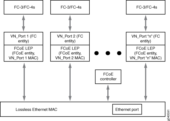
Each FCoE device has a converged network adapter (CNA) that combines the functions of an FC host bus adapter (HBA) and a lossless Ethernet network interface card (NIC) with 10-Gbps Ethernet ports. The portion of the CNA that handles FCoE traffic is called an FCoE Node (ENode). An ENode combines FCoE termination functions and the client part of the FC stack on the CNA.
ENodes present virtual FC interfaces to FC switches in the form of virtual N_Ports (VN_Ports). A VN_Port is an endpoint in a virtual point-to-point connection called a virtual link. The other endpoint of the virtual link is an FC switch (or FCF) port. A VN_Port emulates a native FC N_Port and performs similar functions: handling the creation, detection, and flow of messages to and from the FC switch. A single ENode can host multiple VN_Ports. Each VN_Port has a separate, unique virtual link with a FC switch.
ENodes contain at least one lossless Ethernet media access controller (MAC). Each Ethernet MAC is paired with an FCoE controller. The lossless Ethernet MAC is a full-duplex Ethernet MAC that implements Ethernet extensions to avoid frame loss due to congestion and supports frames of at least 2500 bytes. The FCoE controller instantiates and terminates VN_Port instances dynamically as they are needed for FCoE sessions. Each VN_Port instance has a unique virtual link to an FC switch.
A session is a fabric login (FLOGI) or fabric discovery (FDISC) login to the FC SAN fabric. Session does not refer to end-to-end server-to-storage sessions.
ENodes also contain one FCoE link end point (LEP) for each VN_Port connection. An FCoE LEP is a virtual FC interface mapped onto the physical Ethernet interface.
An FCoE LEP:
Transmits and receives FCoE frames on the virtual link.
Handles FC frame encapsulation for traffic going from the server to the FC switch.
Performs frame de-encapsulation of traffic received from the FC switch.
Figure 1 shows a block diagram of the major ENode components.
FCoE Frames
The FCoE protocol specification replaces the FC0 and FC1 layers of the FC stack with Ethernet, but retains the FC frame header. Retaining the FC frame header enables the FC frame to pass directly to a native FC SAN after de-encapsulation. The FCoE header carries the FC start of file (SOF) bits and end of file (EOF) bits in an encoded format. FCoE supports two frame types, control frames and data frames. FCoE Initialization Protocol (FIP) carries all of the discovery and fabric login frames.
FIP control frames handle FCoE device discovery, initializing communication, and maintaining communication. They do not carry a data payload. FIP has its own EtherType (0x8914) to distinguish FIP traffic from FCoE traffic and other Ethernet traffic. To establish communication, the ENode uses the globally unique MAC address assigned to it by the CNA manufacturer.
After FIP establishes a connection between FCoE devices, the FCoE data frames handle the transport of the FC frames encapsulated in Ethernet. FCoE also has its own EtherType (0x8906) to distinguish FCoE frames from other Ethernet traffic and ensure the in-order frame handling that FC requires. FCoE frames include:
2112 bytes FC payload
24 bytes FC header
14 bytes standard Ethernet header
14 bytes FCoE header
8 bytes cyclic redundancy check (CRC) plus EOF
4 bytes VLAN header
4 bytes frame check sequence (FCS)
The payload, headers, and checks add up to 2180 bytes. Therefore, interfaces that carry FCoE traffic should have a configured maximum transmission unit (MTU) of 2180 or larger. An MTU size of 2180 bytes is the minimum size; some network administrators prefer an MTU of 2240 or 2500 bytes.
Virtual Links
Native FC uses point-to-point physical links between FC devices. In FCoE, virtual links replace the physical links. A virtual link emulates a point-to-point link between two FCoE device endpoints, such as a server VN_Port and an FC switch (or FCF) VF_Port.
Each FCoE interface can support multiple virtual links. The MAC addresses of the FCoE endpoints (the VN_Port and the VF_Port) uniquely identify each virtual link and allow traffic for multiple virtual links to share the same physical link while maintaining data separation and security.
A virtual link exists in one FCoE VLAN and cannot belong to more than one VLAN. Although the FC switch and the FCoE device detect a virtual link as a point-to-point connection, virtual links do not need to be direct connections between a VF_Port and a VN_Port. A virtual link can traverse one or more transit switches, also known as passthrough switches. A transit switch can transparently aggregate virtual links while still appearing and functioning as a point-to-point connection to the FCoE devices. However, a virtual link must remain within a single Layer 2 domain.
FCoE VLANs
All FCoE traffic must travel in a VLAN dedicated to transporting only FCoE traffic. Only FCoE interfaces should be members of an FCoE VLAN. Ethernet traffic that is not FCoE or FIP traffic must travel in a different VLAN.
On a standalone switch or QFabric system Node device, the same VLAN cannot be used in both transit switch mode and FCoE-FC gateway mode.
FCoE VLANs (any VLAN that carries FCoE traffic) support only Spanning Tree Protocol (STP) and link aggregation group (LAG) Layer 2 features.
FCoE traffic cannot use a standard LAG because traffic might be hashed to different physical LAG links on different transmissions. This breaks the (virtual) point-to-point link that Fibre Channel traffic requires. If you configure a standard LAG interface for FCoE traffic, FCoE traffic might be rejected by the FC SAN.
QFabric systems support a special LAG called an FCoE LAG, which enables you to transport FCoE traffic and regular Ethernet traffic (traffic that is not FCoE traffic) across the same link aggregation bundle. Standard LAGs use a hashing algorithm to determine which physical link in the LAG is used for a transmission, so communication between two devices might use different physical links in the LAG for different transmissions. An FCoE LAG ensures that FCoE traffic uses the same physical link in the LAG for requests and replies in order to preserve the virtual point-to-point link between the FCoE device converged network adapter (CNA) and the FC SAN switch across the QFabric system Node device. An FCoE LAG does not provide load balancing or link redundancy for FCoE traffic. However, regular Ethernet traffic uses the standard hashing algorithm and receives the usual LAG benefits of load balancing and link redundancy in an FCoE LAG.
IGMP snooping is enabled by default on all VLANs in all software versions before Junos OS R13.2. Disable IGMP snooping on FCoE VLANs if you are using software that is older than 13.2.
You can configure more than one FCoE VLAN, but any given virtual link must be in only one FCoE VLAN.
All 10-Gigabit Ethernet interfaces that connect to FCoE devices must have a native VLAN configured in order to transport FIP traffic, because FIP VLAN discovery and notification frames are exchanged as untagged packets.
On switches that use the Enhanced Layer 2 Software (ELS) CLI, it is not sufficient only to configure the native VLAN on the interface, the interface must also be configured as a member of the native VLAN. (This is because the ELS CLI does not support tagged-access interface mode, so interfaces that are members of FCoE VLANs must use trunk mode, and trunk port interfaces must be explicitly included as members of a native VLAN.)
In addition, the VLAN ID must match the native VLAN ID that
you configure on the physical interface. For example, to configure
a native VLAN with an ID of 20 on interface xe-0/0/15 that is a member of an FCoE VLAN, you must include both of the following
statements in the configuration:
Configure the native VLAN on the interface:
user@switch# set interfaces xe-0/0/15 native-vlan-id 20
(The equivalent configuration statement on a non-ELS device switch would be set interfaces xe-0/0/15 unit 0 family ethernet-switching native-vlan-id 20.)
Configure the port as a member of the native VLAN (this step is not required on switches that do not use the ELS software):
user@switch# set interfaces xe-0/0/15 unit 0 family ethernet-switching vlan members 20
Only FCoE traffic is permitted on the FCoE VLAN. A native VLAN might need to carry untagged traffic of different types and protocols. Therefore, it is a good practice to keep the native VLAN separate from FCoE VLANs.