Configure Static Routes
Understand Basic Static Routing
Static routing is often used when the complexity of a dynamic routing protocol is not desired. A route that does not frequently change, and for which there is only one (or very few) paths to the destination, is a good candidate for static routing. The classic use case for static routing is a single-homed customer attaching to an upstream provider. This type of attachments creates a stub network.
Static routes are defined manually. The route consist of a destination prefix and a next-hop forwarding address. The static route is activated in the routing table and inserted into the forwarding table when the next-hop address is reachable. Traffic that matches the static route is forwarded to the specified next-hop address.
You can specify options that define additional information about static routes. These attributes, for example a community tag or a route metric, are included with the route when it’s installed in the routing table. These additional route attributes are not required for basic static routing.
Example: Configure IPv4 Static Routing for a Stub Network
Our content testing team has validated and updated this example.
This example shows how to configure basic static routing for IPv4.
Requirements
Two devices running Junos OS with a shared network link. No special configuration beyond basic device initialization (management interface, remote access, user login accounts, and so on), is required before you configure this example.
IPv4 Static Routing Overview
There are many practical applications for static routes. Static routing is often used at the network edge to support attachment to stub networks. Stub networks have a single point of entry and egress, making them well suited to the simplicity of a static route. In Junos OS, static routes have a global preference (administrative distance) of 5. This value makes them preferred over routes learned from dynamic protocols like OSPF or BGP.
IPv4 Static Routing Topology
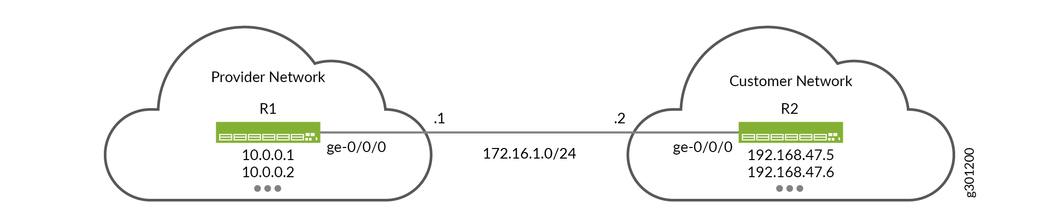
Figure 1 shows the example topology.
In this example, you configure the static route 192.168.47.0/24 on the provider device (R1), using a next-hop address of 172.16.1.2. This route allows the provider device to reach the remote networks at the customer site. You also configure a static default route of 0.0.0.0/0 on the customer device (R2), using a next-hop address of 172.16.1.1. The default route ensures the customer can reach all nonlocal networks by forwarding this traffic to the provider network.
Multiple loopback addresses are configured on both devices. These loopback addresses provide remote destinations to ping, so you can verify the IPv4 static routing works properly.
IPv4 Static Route Configuration
CLI Quick Configuration
To quickly configure basic IPv4 static routing
on the R1 and R2 devices, edit the following commands as needed and
paste them into the CLI at the [edit] hierarchy level.
Be sure to issue a commit from configuration mode to activate
the changes.
R1 Device (Provider)
set system host-name R1
set interfaces ge-0/0/0 unit 0 description “Link from R1 to R2”
set interfaces ge-0/0/0 unit 0 family inet address 172.16.1.1/24
set interfaces lo0 unit 0 family inet address 10.0.0.1/32
set interfaces lo0 unit 0 family inet address 10.0.0.2/32
set routing-options static route 192.168.47.0/24 next-hop 172.16.1.2
R2 Device (Customer)
set system host-name R2
set interfaces ge-0/0/0 unit 0 description “Link from R2 to R1”
set interfaces ge-0/0/0 unit 0 family inet address 172.16.1.2/24
set interfaces lo0 unit 0 family inet address 192.168.47.5/32
set interfaces lo0 unit 0 family inet address 192.168.47.6/32
set routing-options static route 0.0.0.0/0 next-hop 172.16.1.1
Configure the R1 and R2 Devices
Step-by-Step Procedure
This example requires that you navigate various levels in the configuration hierarchy. For information about navigating the CLI, see Using the CLI Editor in Configuration Mode in the Junos OS CLI User Guide.
To configure basic static routes:
Configure the hostname on the R1 (provider) device.
[edit ]
user@R1# set system host-name R1
Configure the interfaces on the R1 (provider) device.
[edit interfaces]
user@R1# set ge-0/0/0 unit 0 description "Link from R1 to R2"
user@R1# set ge-0/0/0 unit 0 family inet address 172.16.1.1/24
user@R1# set lo0 unit 0 family inet address 10.0.0.1/32
user@R1# set lo0 unit 0 family inet address 10.0.0.2/32
Define the static route to the customer’s prefix on the R1 device. Be sure to specify the R2 end of the point-to-point link as the next hop for the static route.
The static route ensures the provider network can route to all remote destinations in the customer network by forwarding traffic through the R2 device.
[edit routing-options]
user@R1# set static route 192.168.47.0/24 next-hop 172.16.1.2
Commit your changes on the R1 device.
[edit ]
user@R1# commit
Configure the hostname on the R2 (customer) device.
[edit ]
user@R2# set system host-name R2
Configure the interfaces on the R2 (customer) device.
[edit interfaces]
user@R2# set ge-0/0/0 unit 0 description "Link from R2 to R1"
user@R2# set ge-0/0/0 unit 0 family inet address 172.16.1.2/24
user@R2# set lo0 unit 0 family inet address 192.168.47.5/32
user@R2# set lo0 unit 0 family inet address 192.168.47.6/32
Define the IPv4 static default route on the R2 device. Be sure to specify the R1 end of the point-to-point link as the next hop for the static route.
The IPv4 default route ensures the customer can route to all nonlocal destinations by forwarding traffic to the R1 device in the provider network.
[edit routing-options]
user@R2# set static route 0.0.0.0/0 next-hop 172.16.1.1
Commit your changes on the R2 device.
[edit]
user@R2# commit
Results
Confirm your configuration by issuing the show
interfaces and show routing-options commands. If
the output does not display the intended configuration, repeat the
instructions in this example to correct the configuration.
R1 Device
user@R1# show interfaces
ge-0/0/0 {
    unit 0 {
        description "Link from R1 to R2";
        family inet {
            address 172.16.1.1/24;
        }
    }
}
lo0 {
    unit 0 {
        family inet {
            address 10.0.0.1/32;
            address 10.0.0.2/32;
        }
    }
}
user@R1# show routing-options
static {
    route 192.168.47.0/24 next-hop 172.16.1.2;
}
R2 Device
user@R2# show interfaces
ge-0/0/0 {
    unit 0 {
        description "Link from R2 to R1";
        family inet {
            address 172.16.1.2/24;
        }
    }
}
lo0 {
    unit 0 {
        family inet {
            address 192.168.47.5/32;
            address 192.168.47.6/32;
        }
    }
}
user@R2# show routing-options
static {
    route 0.0.0.0/0 next-hop 172.16.1.1;
}
Verification
Confirm your IPv4 static routing is working properly.
Check the Routing Tables
Purpose
Confirm the IPv4 static routes are listed as active in the routing tables of both devices.
Action
user@R1> show route
inet.0: 5 destinations, 5 routes (5 active, 0 holddown, 0 hidden)
+ = Active Route, - = Last Active, * = Both

10.0.0.1/32        *[Direct/0] 00:29:43
                    > via lo0.0
10.0.0.2/32        *[Direct/0] 00:29:43
                    > via lo0.0
172.16.1.0/24      *[Direct/0] 00:34:40
                    > via ge-0/0/0.0
172.16.1.1/32      *[Local/0] 00:34:40
                      Local via ge-0/0/0.0
192.168.47.0/24    *[Static/5] 00:31:23
                    > to 172.16.1.2 via ge-0/0/0.0
user@R2> show route
inet.0: 5 destinations, 5 routes (5 active, 0 holddown, 0 hidden)
+ = Active Route, - = Last Active, * = Both

0.0.0.0/0          *[Static/5] 00:31:24
                    > to 172.16.1.1 via ge-1/2/0.1
172.16.1.0/24      *[Direct/0] 00:35:21
                    > via ge-0/0/0.0
172.16.1.2/32      *[Local/0] 00:35:21
                      Local via ge-0/0/0.0
192.168.47.5/32    *[Direct/0] 00:35:22
                    > via lo0.0
192.168.47.6/32    *[Direct/0] 00:35:21
                    > via lo0.0
Meaning
The output confirms the static routes are present in
the routing tables of both devices. The * symbol indicates the routes are active. The next hop for the static
routes correctly point to the IP address assigned to the remote end
of the link.
Ping the Remote Loopback Addresses
Purpose
Verify that the IPv4 static routes provide connectivity
between the loopback addresses of both devices. It’s a good
idea to source your test traffic from a loopback address on the local
device using the source option. This approach validates
forwarding between the loopback addresses of both devices in a single
command.
From the R1 device, ping a loopback interface address on the R2 device.
From the R2 device, ping a loopback interface address on the R1 device.
Action
user@R1> ping 192.168.47.5 count 2 source 10.0.0.1
PING 192.168.47.5 (192.168.47.5): 56 data bytes
64 bytes from 192.168.47.5: icmp_seq=0 ttl=64 time=1.344 ms
64 bytes from 192.168.47.5: icmp_seq=1 ttl=64 time=1.279 ms

--- 192.168.47.5 ping statistics ---
2 packets transmitted, 2 packets received, 0% packet loss
round-trip min/avg/max/stddev = 1.279/1.312/1.344/0.032 ms
user@R2> ping 10.0.0.1 count 2 source 192.168.47.5
PING 10.0.0.1 (10.0.0.1): 56 data bytes
64 bytes from 10.0.0.1: icmp_seq=0 ttl=64 time=1.939 ms
64 bytes from 10.0.0.1: icmp_seq=1 ttl=64 time=2.139 ms

--- 10.0.0.1 ping statistics ---
2 packets transmitted, 2 packets received, 0% packet loss
round-trip min/avg/max/stddev = 1.939/2.039/2.139/0.100 ms
Meaning
The output confirms the static routes allow traffic to be forwarded between the provider and customer networks.
Example: Configure IPv6 Static Routing for a Stub Network
Our content testing team has validated and updated this example.
This example shows how to configure basic static routes for IPv6.
Requirements
Two devices running Junos OS with a shared network link. No special configuration beyond basic device initialization (management interface, remote access, user login accounts, and so on), is required before you configure this example.
IPv6 Static Routing Overview
There are many practical applications for static routes. Static routing is often used at the network edge to support attachment to stub networks, which, given their single point of entry and egress, are well suited to the simplicity of a static route. In Junos OS, static routes have a global preference of 5. Static routes are activated when the specified next hop is reachable.
You can specify options that define additional information about static IPv6 routes. These attributes, for example a community tag or route metric, are included with the route when it’s installed in the routing table. These additional route attributes are not required for basic IPv6 static routing.
IPv6 Static Routing Topology
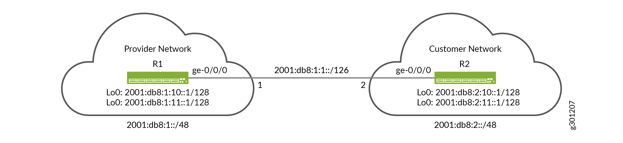
Figure 2 provides the IPv6 static routing topology.
In this example the provider and customer networks have been allocated the IPv6 prefixes 2001:db8:1::/48 and 2001:db8:2::/48, respectively. Both networks are free to allocate longer prefixes (subnetworks) from their assigned prefix block. The point-to-point link is numbered from the provider’s address space using a /126 prefix length. Each device has two loopback addresses allocated from their assigned prefix using a /128 prefix length.
You configure a static route to the customer prefix (2001:db8:2::/48) on the provider (R1) network device, using a next hop of 2001:db8:1:1::2. This route provides reachability from the provider device to the remote networks at the customer site. On the customer device (R2), you configure a static default route of ::/0, using a next-hop address 2001:db8:1:1::1. The default route provides the customer with reachability to all nonlocal prefixes through the provider’s network.
Multiple loopback addresses are configured on both devices. These loopback addresses provide remote destinations to ping, allowing you to verify the IPv6 static routing works properly.
IPv6 Static Route Configuration
CLI Quick Configuration
To quickly configure basic IPv6 static routing
on the R1 and R2 devices, edit the following commands as needed and
paste them into the CLI at the [edit] hierarchy level.
Be sure to issue a commit from configuration mode to activate
the changes.
R1 Device (Provider)
set system host-name R1
set interfaces ge-0/0/0 description "Link from R1 to R2"
set interfaces ge-0/0/0 unit 0 family inet6 address 2001:db8:1:1::1/126
set interfaces lo0 unit 0 family inet6 address 2001:db8:1:10::1/128
set interfaces lo0 unit 0 family inet6 address 2001:db8:1:11::1/128
set routing-options rib inet6.0 static route 2001:db8:2::/48 next-hop 2001:db8:1:1::2
R2 Device (Customer)
set system host-name R2
set interfaces ge-0/0/0 description "Link from R2 to R1"
set interfaces ge-0/0/0 unit 0 family inet6 address 2001:db8:1:1::2/126
set interfaces lo0 unit 0 family inet6 address 2001:db8:2:10::1/128
set interfaces lo0 unit 0 family inet6 address 2001:db8:2:11::1/128
set routing-options rib inet6.0 static route ::/0 next-hop 2001:db8:1:1::1
Configure the R1 and R2 Devices
Step-by-Step Procedure
This example that you navigate various levels in the configuration hierarchy. For information about navigating the CLI, see Using the CLI Editor in Configuration Mode in the Junos OS CLI User Guide.
Follow these steps to configure basic IPv6 static routes:
Configure the hostname on the R1 (provider) device.
[edit ]
user@R1# set system host-name R1
Configure the interfaces on the R1 (provider) device.
[edit interfaces]
user@R1# set ge-0/0/0 description "Link from R1 to R2"
user@R1# set ge-0/0/0 unit 0 family inet6 address 2001:db8:1:1::1/126
user@R1# set lo0 unit 0 family inet6 address 2001:db8:1:10::1/128
user@R1# set lo0 unit 0 family inet6 address 2001:db8:1:11::1/128
Define the static route to the customer’s IPv6 prefix on the R1 device. Be sure to set the next-hop address to the customer end of the point-to-point link.
The use of a /48 bit prefix length ensures that the R1 device can reach all possible remote destinations in the customer network by forwarding through the R2 device.
[edit routing-options]
user@R1# set rib inet6.0 static route 2001:db8:2::/48 next-hop 2001:db8:1:1::2
Commit your changes on the R1 device.
[edit ]
user@R1# commit
Configure the hostname on the R2 (customer) device.
[edit ]
user@R2# set system host-name R2
Configure the interfaces on the R2 (customer) device.
[edit interfaces]
user@R2# set ge-0/0/0 description "Link from R2 to R1"
user@R2# set ge-0/0/0 unit 0 family inet6 address 2001:db8:1:1::2/126
user@R2# set lo0 unit 0 family inet6 address 2001:db8:2:10::1/128
user@R2# set lo0 unit 0 family inet6 address 2001:db8:2:10::2/128
Define the IPv6 static default route on the R2 device. Be sure to set the next-hop address to the provider end of the point-to-point link.
The IPv6 default route ensures that the R2 device can reach all nonlocal destinations by forwarding traffic through the R1 device in the provider network.
[edit routing-options]
user@R2# set rib inet6.0 static route ::/0 next-hop 2001:db8:1:1::1
Commit your changes on the R2 device.
[edit]
user@R2# commit
Results
Confirm your configuration by issuing the show
interfaces and show routing-options commands. If
the output does not display the intended configuration, repeat the
instructions in this example to correct the configuration.
R1 Device
user@R1# show interfaces
ge-0/0/0 {
    description "Link from R1 to R2";
    unit 0 {
        family inet6 {
            address 2001:db8:1:1::1/126;
        }
    }
}
lo0 {
    unit 0 {
        family inet6 {
            address 2001:db8:1:10::1/128;
            address 2001:db8:1:11::1/128;
        }
    }
}
user@R1# show routing-options
rib inet6.0 {
    static {
        route 2001:db8:2::/48 next-hop 2001:db8:1:1::2;
    }
}
R2 Device
user@R2# show interfaces
ge-0/0/0 {
    description "Link from R2 to R1";
    unit 0 {
        family inet6 {
            address 2001:db8:1:1::2/126;
        }
    }
}
lo0 {
    unit 0 {
        family inet6 {
            address 2001:db8:2:10::1/128;
            address 2001:db8:2:11::1/128;
        }
    }
}
user@R2# show routing-options
rib inet6.0 {
    static {
        route ::/0 next-hop 2001:db8:1:1::1;
    }
}
Verification
Confirm IPv6 static routing works properly.
Checking the Routing Tables
Purpose
Verify the IPv6 static routes are active in the routing tables of both devices.
Action
user@R1> show route protocol static
inet6.0: 8 destinations, 8 routes (8 active, 0 holddown, 0 hidden)
+ = Active Route, - = Last Active, * = Both

2001:db8:2::/48    *[Static/5] 02:07:11
                    >  to 2001:db8:1:1::2 via ge-0/0/0.0
user@R2> show route protocol static
inet6.0: 8 destinations, 8 routes (8 active, 0 holddown, 0 hidden)
+ = Active Route, - = Last Active, * = Both

::/0               *[Static/5] 02:13:56
                    >  to 2001:db8:1:1::1 via ge-0/0/0.0
Meaning
The output confirms the IPv6 static routes are present
in the routing tables of both devices. The * symbol indicates the routes are active. Both the static routes correctly
point to the remote end of the point-to-point link as the next hop
for matching traffic.
Ping the Remote Loopback Addresses
Purpose
Verify that the IPv6 static routes provide connectivity
between the loopback addresses of both devices. It’s a good
idea to source your test traffic from a loopback address on the local
device using the source option. This approach validates
forwarding between the loopback addresses of both devices in a single
command.
From the R1 device, ping a loopback address on the R2 device.
From the R2 device, ping q loopback address on the R1 device.
Action
user@R1> ping 2001:db8:2:10::1 source 2001:db8:1:10::1 count 2
PING6(56=40+8+8 bytes) 2001:db8:1:10::1 --> 2001:db8:2:10::1
16 bytes from 2001:db8:2:10::1, icmp_seq=0 hlim=64 time=2.770 ms
16 bytes from 2001:db8:2:10::1, icmp_seq=1 hlim=64 time=2.373 ms

--- 2001:db8:2:10::1 ping6 statistics ---
2 packets transmitted, 2 packets received, 0% packet loss
round-trip min/avg/max/std-dev = 2.373/2.572/2.770/0.198 ms
user@R2> ping 2001:db8:1:10::1 source 2001:db8:2:10::1 count 2
PING6(56=40+8+8 bytes) 2001:db8:2:10::1 --> 2001:db8:1:10::1
16 bytes from 2001:db8:1:10::1, icmp_seq=0 hlim=64 time=1.985 ms
16 bytes from 2001:db8:1:10::1, icmp_seq=1 hlim=64 time=1.704 ms

--- 2001:db8:1:10::1 ping6 statistics ---
2 packets transmitted, 2 packets received, 0% packet loss
round-trip min/avg/max/std-dev = 1.704/1.845/1.985/0.140 ms
Meaning
The output confirms the IPv6 static routes allow traffic to be forwarded between the provider and customer networks.