SCU with Layer 3 VPNs Configuration
Configuring SCU in a Layer 3 VPN
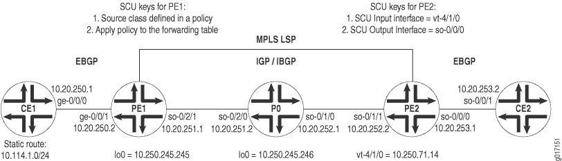
Figure 1 displays a Layer 3 VPN topology. CE1 and CE2 are customer edge (CE) routers connected by a VPN through provider routers PE1, P0, and PE2. EBGP is established between routers CE1 and PE1, IBGP connects routers PE1 and PE2 over an IS-IS/MPLS/LDP core, and a second EBGP connection flows between routers PE2 and CE2.
On Router CE1, begin your VPN by setting up an
EBGP connection to PE1. Install a static route of 10.114.1.0/24 and advertise this route to your EBGP neighbor.
Router CE1
[edit]
interfaces {
    ge-0/0/0 {
        unit 0 {
            family inet {
                address 10.20.250.1/30;
            }
        }
    }
}
routing-options {
    static {
        route 10.114.1.0/24 reject;
    }
    autonomous-system 100;
}
protocols {
    bgp {
        group to-pe1 {
            local-address 10.20.250.1;
            export inject-direct;
            peer-as 300;
            neighbor 10.20.250.2;
        }
    }
}
policy-options {
    policy-statement inject-direct {
        term 1 {
            from {
                protocol static;
                route-filter 10.114.1.0/24 exact;
            }
            then accept;
        }
        term 2 {
            from protocol direct;
            then accept;
        }
    }
}
On PE1, complete the EBGP connection to CE1 through a VRF routing instance. Set an export policy for your VRF instance that puts BGP traffic into a community, and an import policy that accepts like community traffic from your VPN neighbor. Lastly, configure an IBGP relationship to Router PE2 that runs over an IS-IS, MPLS, and LDP core.
Router PE1
[edit]
interfaces {
    ge-0/0/1 {
        unit 0 {
            family inet {
                address 10.20.250.2/30;
            }
        }
    }
    so-0/2/1 {
        unit 0 {
            family inet {
                address 10.20.251.1/30;
            }
            family iso;
            family mpls;
        }
    }
    lo0 {
        unit 0 {
            family inet {
                address 10.250.245.245/32;
            }
            family iso;
            family mpls;
        }
    }
}
routing-options {
    autonomous-system 300;
}
protocols {
    mpls {
        interface so-0/2/1;
    }
    bgp {
        group ibgp {
            type internal;
            local-address 10.250.245.245;
            family inet-vpn {
                unicast;
            }
            neighbor 10.250.71.14;
        }
    }
    isis {
        interface so-0/2/1;
    }
    ldp {
        interface so-0/2/1;
    }
}
policy-options {
    policy-statement red-import {
        from {
            protocol bgp;
            community red-com;
        }
        then accept;
    }
    policy-statement red-export {
        from protocol bgp;
        then {
            community add red-com;
            accept;
        }
    }
    community red-com members target:20:20;
}
routing-instances {
    red {
        instance-type vrf;
        interface ge-0/0/1.0;
        route-distinguisher 10.250.245.245:100;
        vrf-import red-import;
        vrf-export red-export;
        protocols {
            bgp {
                group to-ce1 {
                    local-address 10.20.250.2;
                    peer-as 100;
                    neighbor 10.20.250.1;
                }
            }
        }
    }
}
On P0, connect the IBGP neighbors located at PE1 and PE2. Remember to include VPN-related protocols (MPLS, LDP, and IGP) on all interfaces.
Router P0
[edit]
interfaces {
    so-0/1/0 {
        unit 0 {
            family inet {
                address 10.20.252.1/30;
            }
            family iso;
            family mpls;
        }
    }
    so-0/2/0 {
        unit 0 {
            family inet {
                address 10.20.251.2/30;
            }
            family iso;
            family mpls;
        }
    }
    lo0 {
        unit 0 {
            family inet {
                address 10.250.245.246/32;
            }
            family iso;
            family mpls;
        }
    }
}
routing-options {
    autonomous-system 300;
}
protocols {
    mpls {
        interface so-0/1/0;
        interface so-0/2/0;
    }
    isis {
        interface all;
    }
    ldp {
        interface all;
    }
}
On PE2, complete the IBGP relationship to Router PE1. Establish
an EBGP connection to CE2 through a VRF routing instance. Set an export
policy for the VRF instance that places BGP traffic into a community,
and an import policy that accepts like community traffic from the
VPN neighbor. Next, establish a policy that adds the static route
from CE1 to a source class called GOLD1. Also, export this
SCU policy into the forwarding table. Finally, set your vt interface as the SCU input interface and establish the CE-facing
interface so-0/0/0 as the SCU output interface.
Router PE2
[edit]
interfaces {
    so-0/1/1 {
        unit 0 {
            family inet {
                address 10.20.252.2/30;
            }
            family iso;
            family mpls;
        }
    }
    so-0/0/0 {
        unit 0 {
            family inet {
                accounting {
                    source-class-usage {
                        output;
                    }
                }
                address 10.20.253.1/30;
            }
        }
    }
    vt-4/1/0 {
        unit 0 {
            family inet {
                accounting {
                    source-class-usage {
                        input;
                    }
                }
                address 10.250.71.14/32;
            }
            family iso;
            family mpls;
        }
    }
}
routing-options {
    autonomous-system 300;
    forwarding-table {
        export inject-customer2-dest-class;
    }
}
protocols {
    mpls {
        interface so-0/1/1;
        interface vt-4/1/0;
    }
    bgp {
        group ibgp {
            type internal;
            local-address 10.250.71.14;
            family inet-vpn {
                unicast;
            }
            neighbor 10.250.245.245;
        }
    }
    isis {
        interface so-0/1/1;
    }
    ldp {
        interface so-0/1/1;
    }
}
routing-instances {
    red {
        instance-type vrf;
        interface so-0/0/0.0;
        interface vt-4/1/0.0;
        route-distinguisher 10.250.71.14:100;
        vrf-import red-import;
        vrf-export red-export;
        protocols {
            bgp {
                group to-ce2 {
                    local-address 10.20.253.1;
                    peer-as 400;
                    neighbor 10.20.253.2;
                }
            }
        }
    }
}
policy-options {
    policy-statement red-import {
        from {
            protocol bgp;
            community red-com;
        }
        then accept;
    }
    policy-statement red-export {
        from protocol bgp;
        then {
            community add red-com;
            accept;
        }
    }
    policy-statement inject-customer2-dest-class {
        term term-gold1-traffic {
            from {
                route-filter 10.114.1.0/24 exact;
            }
            then source-class GOLD1;
        }
    }
    community red-com members target:20:20;
}
On Router CE2, complete the VPN path by finishing the EBGP connection to PE2.
Router CE2
[edit]
interfaces {
    so-0/0/1 {
        unit 0 {
            family inet {
                address 10.20.253.2/30;
            }
        }
    }
}
routing-options {
    autonomous-system 400;
}
protocols {
    bgp {
        group to-pe2 {
            local-address 10.20.253.2;
            export inject-direct;
            peer-as 300;
            neighbor 10.20.253.1;
        }
    }
}
policy-options {
    policy-statement inject-direct {
        from {
            protocol direct;
        }
        then accept;
    }
}
Verifying Your Work
To verify that SCU is functioning properly in the Layer 3 VPN, use the following commands:
show interfaces interface-name statisticsshow interfaces source-class source-class-name interface-nameshow interfaces interface-name(extensive|detail)show route(extensive|detail)clear interface interface-name statistics
You should always verify SCU statistics at the
outbound SCU interface on which you configured the output statement. To check SCU functionality, follow these steps:
Clear all counters on your SCU-enabled router and verify they are empty.
Send a ping from the ingress CE router to the second CE router to generate SCU traffic across the SCU-enabled VPN route.
Verify that the counters are incrementing correctly on the outbound interface.
The following section shows the output of these commands used with the configuration example.
user@pe2> clear interfaces statistics all

	user@pe2> show interfaces so-0/0/0.0 statistics
  	Logical interface so-0/0/0.0 (Index 6) (SNMP ifIndex 113)
    Flags: Point-To-Point SNMP-Traps Encapsulation: PPP
    Protocol inet, MTU: 4470
      Source class                             Packets                Bytes
 GOLD1                          0                    0
      Addresses, Flags: Is-Preferred Is-Primary

	user@pe2> show interfaces source-class GOLD1 so-0/0/0.0
    Protocol inet
      Source class                             Packets                Bytes
GOLD1                          0                    0

user@ce1> ping 10.20.253.2 source 10.114.1.1 rapid count 10000

user@scu>  show interfaces source-class GOLD1 so-0/0/0.0
    Protocol inet
      Source class                             Packets                Bytes
GOLD1                      20000              1680000

user@scu>  show interfaces so-0/0/0.0 statistics
  Logical interface so-0/0/0.0 (Index 6) (SNMP ifIndex 113)
    Flags: Point-To-Point SNMP-Traps Encapsulation: PPP
    Protocol inet, MTU: 4470
      Source class                             Packets                Bytes
GOLD1                      20000              1680000
      Addresses, Flags: Is-Preferred Is-Primary
         Destination: 10.20.253/24, Local: 10.20.253.1