Help us improve your experience.

Let us know what you think.

Do you have time for a two-minute survey?


Ethernet OAM and CFM for Switches

SUMMARY This section describes how ethernet interfaces on Juniper Networks Switches and Juniper Networks Junos operating system (Junos OS) for switches support the IEEE 802.1ag standard for Operation, Administration, and Management (OAM).

Understanding Ethernet OAM Connectivity Fault Management for Switches

The IEEE 802.1ag specification provides for Ethernet connectivity fault management (CFM). CFM monitors Ethernet networks that might comprise one or more service instances for network-compromising connectivity faults.

The major features of CFM are:

  • Fault monitoring using the continuity check protocol. This is a neighbor discovery and health check protocol that discovers and maintains adjacencies at the VLAN level.

  • Path discovery and fault verification using the linktrace protocol.

  • Fault isolation using the loopback protocol.

CFM partitions the service network into various administrative domains. For example, operators, providers, and customers might be part of different administrative domains. Each administrative domain is mapped into one maintenance domain providing enough information to perform its own management, thus avoiding security breaches and making end-to-end monitoring possible.

In a CFM maintenance domain, each service instance is called a maintenance association. A maintenance association can be thought of as a full mesh of maintenance association endpoints (MEPs) having similar characteristics. MEPs are active CFM entities generating and responding to CFM protocol messages. There is also a maintenance intermediate point (MIP), which is a CFM entity similar to the MEP, but more passive (MIPs only respond to CFM messages).

Each maintenance domain is associated with a maintenance domain level from 0 through 7. Level allocation is based on the network hierarchy, where outer domains are assigned a higher level than the inner domains. Configure customer end points to have the highest maintenance domain level. The maintenance domain level is a mandatory parameter that indicates the nesting relationships between various maintenance domains. The level is embedded in each CFM frame. CFM messages within a given level are processed by MEPs at that same level.

To enable CFM on an Ethernet interface, you must configure maintenance domains, maintenance associations, and maintenance association end points (MEPs). Figure 1 shows the relationships among maintenance domains, maintenance association end points (MEPs), and maintenance intermediate points (MIPs) configured on a switch.
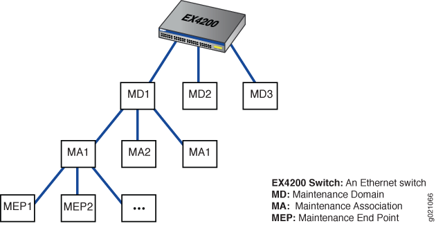
Figure 1: Relationship Among MEPs, MIPs, and Maintenance Domain Levels Relationship Among MEPs, MIPs, and Maintenance Domain Levels

CFM Limitations on EX4600 Switches

Starting in Junos OS Release 18.3R1, Junos OS provides CFM support on EX4600. CFM support on EX4600 has the following limitations:

  • CFM support is provided via software using filters. This can impact scaling.

  • Inline Packet Forwarding Engine (PFE) mode is not supported. In Inline PFE mode, you can delegate periodic packet management (PPM) processing to the Packet Forwarding Engine (PFE) which results in faster packet handling and the CCM interval supported is 10 milliseconds.

  • Performance monitoring (ITU-T Y.1731 Ethernet Service OAM) is not supported.

  • CCM interval of less than 1 second is not supported.

  • CFM is not supported on Routed Interfaces and aggregated Ethernet (lag) interfaces.

  • MIP half function, to divide the MIP functionality into two unidirectional segments to improve network coverage, is not supported.

  • Up MEP is not supported.

  • Total number of CFM sessions supported is 20.

CFM Limitations on QFX5120, QFX5200, and QFX5210 Series Switches

Starting in Junos OS Release 18.4R1, Junos OS provides CFM support on QFX5200 switches and QFX5210 switches. Starting in Junos OS Release 19.4R1, Junos OS provides CFM support on QFX5120 switches. CFM support on QFX5120, QFX5200, and QFX5210 Series switches has the following limitations:

  • CFM support is provided via software using filters. This can impact scaling.

  • Inline Packet Forwarding Engine (PFE) mode is not supported. In Inline PFE mode, you can delegate periodic packet management (PPM) processing to the Packet Forwarding Engine (PFE) which results in faster packet handling and the CCM interval supported is 10 milliseconds.

  • Performance monitoring (ITU-T Y.1731 Ethernet Service OAM) is not supported.

  • CCM interval of less than 1 second is not supported.

  • CFM is not supported on Routed Interfaces and aggregated Ethernet (lag) interfaces.

  • MIP half function, to divide the MIP functionality into two unidirectional segments to improve network coverage, is not supported.

  • Up MEP is not supported.

  • Total number of CFM sessions supported is 20.

Configuring Ethernet OAM Connectivity Fault Management (CLI Procedure)

Ethernet interfaces on Juniper Networks EX Series Ethernet Switches and Juniper Networks Junos OS for EX Series switches support the IEEE 802.1ag standard for Operation, Administration, and Management (OAM). The IEEE 802.1ag specification provides for Ethernet connectivity fault management (CFM).

Note:

This feature is not supported on EX4300 switches on aggregated Ethernet (LAG) interfaces.

This topic describes these tasks:

Creating the Maintenance Domain

A maintenance domain comprises network entities such as operators, providers, and customers. To enable connectivity fault management (CFM) on an Ethernet interface, you must create a maintenance domains, maintenance associations, and MEPs.

To create a maintenance domain:

  1. Specify a name for the maintenance domain:
  2. Specify a format for the maintenance domain name. If you specify none, no name is configured:
    • A plain ASCII character string

    • A domain name service (DNS) format

    • A media access control (MAC) address plus a two-octet identifier in the range 0 through 65,535

    • none

    For example, to specify the name format as MAC address plus a two-octet identifier:

  3. Configure the maintenance domain level, which is used to indicate the nesting relationship between this domain and other domains. Use a value from 0 through 7:

Configuring the Maintenance Domain MIP Half Function

Note:

MIP Half Function (MHF) is not supported on EX4600, QFX5200, and QFX5210 switches.

MIP Half Function (MHF) divides the maintenance association intermediate point (MIP) functionality into two unidirectional segments, improves visibility with minimal configuration, and improves network coverage by increasing the number of points that can be monitored. MHF extends monitoring capability by responding to loop-back and link-trace messages to help isolate faults. Whenever a MIP is configured, the MIP half function value for all maintenance domains and maintenance associations must be the same.

To configure the MIP half function:

Creating a Maintenance Association

In a CFM maintenance domain, each service instance is called a maintenance association.

To create a maintenance association:

Configuring the Continuity Check Protocol

The continuity check protocol is used for fault detection by a maintenance association end point (MEP) within a maintenance association. The MEP periodically sends continuity check multicast messages. The receiving MEPs use the continuity check messages (CCMs) to build a MEP database of all MEPs in the maintenance association.

To configure the continuity check protocol:

  1. Enable the continuity check protocol:
  2. Specify the continuity check hold interval. The hold interval is the number of minutes to wait before flushing the MEP database if no updates occur. The default value is 10 minutes.
  3. Specify the CCM interval. The interval is the time between the transmission of CCMs. You can specify 10 minutes (10m), 1 minute (1m), 10 seconds (10s), 1 second (1s), 100 milliseconds (100ms), or 10 milliseconds (10ms).
    Note:

    On EX4600, QFX5200, and QFX5210 switches, CCM interval of less than 1 second is not supported.

  4. Specify the number of CCMs (that is, protocol data units) that can be lost before the MEP is marked as down. The default number of protocol data units (PDUs) is 3.

Configuring a Maintenance Association End Point

To configure a maintenance association end point:

  1. Specify an ID for the MEP. The value can be from 1 through 8191.
  2. Enable maintenance endpoint automatic discovery if you want to have the MEP accept continuity check messages (CCMs) from all remote MEPs of the same maintenance association:
  3. You can specify that CFM packets (CCMs) be transmitted only in one direction for the MEP, that is, the direction be set as down so that CCMs are transmitted only out of (not into) the interface configured on this MEP.
  4. Specify the logical interface to which the MEP is attached. It can be either an access interface or a trunk interface. If you specify a trunk interface, the VLAN associated with that interface must have a VLAN ID.
    Note:

    You cannot associate an access interface that belongs to multiple VLANs with the MEP.

  5. You can configure a remote MEP from which CCMs are expected. If autodiscovery is not enabled, the remote MEP must be configured under the mep statement. If the remote MEP is not configured under the mep statement, the CCMs from the remote MEP are treated as errors.

Configuring a Connectivity Fault Management Action Profile

You can configure an action profile and specify the action to be taken when any of the configured events occur. Alternatively, you can configure an action profile and specify default actions when connectivity to a remote MEP fails.

To configure an action profile:

  1. Specify a name for an action profile:
  2. Configure the action of the action profile:
  3. Configure one or more events under the action profile, the occurrence of which will trigger the corresponding action to be taken:

Configuring the Linktrace Protocol

The linktrace protocol is used for path discovery between a pair of maintenance points. Linktrace messages are triggered by an administrator using the traceroute command to verify the path between a pair of MEPs under the same maintenance association. Linktrace messages can also be used to verify the path between a MEP and a MIP under the same maintenance domain.

To configure the linktrace protocol:

  1. Configure the linktrace path age timer. If no response to a linktrace request is received, the request and response entries are deleted after the age timer expires:
  2. Configure the number of linktrace reply entries to be stored per linktrace request:

Example: Configuring Ethernet OAM Connectivity Fault Management on EX Series Switches

Ethernet interfaces on EX Series switches and Junos OS for EX Series switches support the IEEE 802.1ag standard for Operation, Administration, and Management (OAM). The IEEE 802.1ag specification provides for Ethernet connectivity fault management (CFM).

This example describes how to enable and configure OAM CFM on a Gigabit Ethernet interface:

Requirements

This example uses the following hardware and software components:

  • Junos OS Release 10.2 or later for EX Series switches

  • Two EX Series switches connected by a point-to-point Gigabit Ethernet link

Overview and Topology

CFM can be used to monitor the physical link between two switches. In the following example, two switches are connected by a point-to-point Gigabit Ethernet link. The link between these two switches is monitored using CFM.

Configuring Ethernet OAM Connectivity Fault Management on Switch 1

CLI Quick Configuration

To quickly configure Ethernet OAM CFM, copy the following commands and paste them into the switch terminal window:

Procedure

Step-by-Step Procedure

To enable and configure OAM CFM on switch 1:

  1. Specify the maintenance domain name format:

  2. Specify the maintenance domain name and the maintenance domain level:

  3. Create a maintenance association:

  4. Enable the continuity check protocol and specify the continuity check hold interval:

  5. Configure the maintenance association end point (MEP):

Results

Check the results of the configuration.

Configuring Ethernet OAM Connectivity Fault Management on Switch 2

CLI Quick Configuration

To quickly configure Ethernet OAM CFM, copy the following commands and paste them into the switch terminal window:

Procedure

Step-by-Step Procedure

The configuration on switch 2 mirrors that on switch 2.

  1. Specify the maintenance domain name format:

  2. Specify the maintenance domain name and the maintenance domain level:

  3. Create a maintenance association:

  4. Enable the continuity check protocol and specify the continuity check hold interval:

  5. Configure the maintenance association end point (MEP)

Results

Check the results of the configuration.

Verification

To confirm that the configuration is working properly, perform these tasks:

Verifying That OAM CFM Has Been Configured Properly

Purpose

Verify that OAM CFM has been configured properly.

Action

Use the show oam ethernet connectivity-fault-management interfaces detail command:

Sample Output
command-name
Meaning

When the output displays that continuity-check status is enabled and displays details of the remote MEP, it means that connectivity fault management (CFM) has been configured properly.