Example: Configuring Automatic VLAN Administration Using MVRP
Multiple VLAN Registration Protocol (MVRP) is used in Layer 2 networks to dynamically share virtual LAN (VLAN) information and to automatically configure necessary VLAN information. Automatically configuring VLANs on ports based on the current network configuration ensures that a router does not send traffic to an interface on the network with an inactive VLAN. In this way, MVRP reduces network overhead by limiting the scope of broadcast, unknown unicast, and multicast (BUM) traffic to interested devices only. MVRP also provides for rapid healing of network failures without interrupting services to unaffected VLANs and improves convergence times.
MVRP is a Layer 2 network protocol based on the IEEE standard 802.1ak amendment to 802.1Q-2005, Standard for Local and Metropolitan Area Networks Virtual Bridged Local Area Networks - Amendment 07: Multiple Registration Protocol.
This example describes how to use MVRP to automate administration of VLAN membership changes within your network and to dynamically create VLANs:
Requirements
This example uses the following hardware and software components:
Two MX routers acting as edge switches
One MX router acting as an aggregation switch
Any supported Junos release
Overview and Topology
VLANs are statically configured on access interfaces on MX routers acting as edge switches. The VLAN membership information is propagated to the MX router acting as an aggregation switch at the core by enabling MVRP on two trunk interfaces:one connecting edge switch 1 (ES1) to aggregation switch 1 (AS1), and the other connecting ES2 to AS1. Enabling MVRP on the trunk interface of each MX router in your network ensures that the active VLAN information for the routers in the network is propagated to each router through the trunk interfaces (the default registration mode for MVRP).
MVRP ensures that the VLAN membership information on the trunk interface is updated as the edge switch’s access interfaces become active or inactive.
You do not need to explicitly bind a VLAN to the trunk interface. When MVRP is enabled, the trunk interface advertises all the VLANs that are active (bound to access interfaces) on that switch. An MVRP-enabled trunk interface does not advertise VLANs that have been configured on the switch but are not currently bound to an access interface. For example, ES1 in the topology does not forward traffic to inactive VLAN 300 on ES2.
Rapid Spanning Tree Protocol (RSTP) is also configured on the trunk interfaces to promote a loop-free topology.
This example shows a network with two customer sites, site–1 and site–2, using VLANs 100, 200, and 300.
ES1 supports all three VLANS, and all three VLANS are active and bound to interfaces that are connected to three customers at site–1:
ge-11/2/6—Access port connecting customer3–site1, VLAN ID 100.
ge-11/2/7—Access port connecting customer2–site1, VLAN ID 200.
ge-11/2/8—Access port connecting customer1–site1, VLAN ID 300.
ge-11/3/0—Trunk port connecting ES1 to AS1.
ES2 has been configured to support two VLANS, and both VLANS are active and bound to interfaces that are connected to two customers at site–2:
ge-0/1/1—Access port connecting customer1–site2, VLAN ID 100.
ge-0/2/0—Access port connecting customer2–site2, VLAN ID 200.
ge-0/0/5—Trunk port connecting ES2 to AS1.
AS1 learns the VLANs dynamically using MVRP through the connection to the edge switches. AS1 has two trunk interfaces:
ge-3/3/0—Connects the router to edge switch ES1 on interface ge-11/3/0.
ge-3/0/5—Connects the router to edge switch ES2 on interface ge-0/0/5.
The default MVRP interface registration mode is normal and is used in this example. An interface in normal registration mode participates in MVRP when MVRP is enabled on the router. For information about changing the MVRP registration mode, see Controlling the Management State of a VLAN in MVRP Configurations .
Topology
Figure 1 shows MVRP configured on three MX routers: two routers operating as edge switches and one router operating as an aggregation switch.
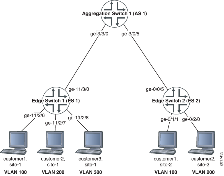
Table 1 explains the components of the example topology.
| Property | Settings |
|---|---|
MX routers |
|
VLAN tag IDs associated with bridge domain bd |
100, 200, and 300 |
ES1 interfaces |
ES1 interfaces:
|
ES2 interfaces |
ES2 interfaces:
|
AS1 interfaces |
AS1 interfaces:
|
Configuration
To enable MVRP and RSTP on the trunk interface, as well as configure ES1 access interfaces and the bridge domain, perform these tasks:
Configuring MVRP on ES1
CLI Quick Configuration
To quickly configure ES1 for MVRP, copy the following commands and paste them into the switch terminal window of ES1:
[edit]

set interfaces ge-11/2/6 description "connected to customer3-site-1"
set interfaces ge-11/2/6 unit 0 family bridge interface-mode access
set interfaces ge-11/2/6 unit 0 family bridge vlan-id 300
set interfaces ge-11/2/7 description "connected to customer2-site-1"
set interfaces ge-11/2/7 unit 0 family bridge interface-mode access
set interfaces ge-11/2/7 unit 0 family bridge vlan-id 200
set interfaces ge-11/2/8 description "connected to customer1-site-1"
set interfaces ge-11/2/8 unit 0 family bridge interface-mode access
set interfaces ge-11/2/8 unit 0 family bridge vlan-id 100
set interfaces ge-11/3/0 description "connected to AS1 interface ge-3/3/0"
set interfaces ge-11/3/0 unit 0 family bridge interface-mode trunk
set bridge-domains bd vlan-id-list [100 200 300]
set protocols mvrp interface ge-11/3/0
set protocols rstp interface ge-11/3/0
As we recommend as a best practice, default MVRP timers are used in this example. The default values associated with each MVRP timer are 200 ms for the join timer, 1000 ms for the leave timer, and 10000 ms for the leaveall timer. Modifying timers to inappropriate values might cause an imbalance in the operation of MVRP.
Step-by-Step Procedure
To configure MVRP on ES1:
Configure the access interfaces for customers at customer-site 1 and the trunk interface connecting ES1 to AS1:
[edit interfaces]
user@es1# set ge-11/2/6 description "connected to customer3-site-1"
user@es1# set ge-11/2/6 unit 0 family bridge interface-mode access
user@es1# set ge-11/2/6 unit 0 family bridge vlan-id 300
user@es1# set ge-11/2/7 description "connected to customer2-site-1"
user@es1# set ge-11/2/7 unit 0 family bridge interface-mode access
user@es1# set ge-11/2/7 unit 0 family bridge vlan-id 200
user@es1# set ge-11/2/8 description "connected to customer1-site-1"
user@es1# set ge-11/2/8 unit 0 family bridge interface-mode access
user@es1# set ge-11/2/8 unit 0 family bridge vlan-id 100
user@es1# set ge-11/3/0 description "connected to AS1 interface ge-3/3/0"
user@es1# set ge-11/3/0 unit 0 family bridge interface-mode trunk
Configure the bridge domain bd and the VLAN IDs associated with the bridge domain:
[edit bridge-domains]
user@es1# set bd vlan-id-list [100 200 300]
Enable MVRP on the trunk interface:
[edit protocols]
user@es1# set mvrpinterface ge-11/3/0
Enable RSTP on the trunk interface:
[edit protocols]
user@es1# set rstp interface ge-11/3/0
Results
Check the results of the configuration:
user@es1> show configuration
interfaces {
    ge-11/2/6 {
        description "connected to customer3-site-1";
        unit 0 {
            family bridge {
                interface-mode access;
                vlan-id 300;
            }
        }
    }
    ge-11/2/7 {
        description "connected to customer2-site-1";
        unit 0 {
            family bridge {
                interface-mode access;
                vlan-id 200;
            }
        }
    }
    ge-11/2/8 {
        description "connected to customer1-site-1";
        unit 0 {
            family bridge {
                interface-mode access;
                vlan-id 100;
            }
        }
    }
    ge-11/3/0 {
        description "connected to AS1 interface ge-3/3/0";
        unit 0 {
            family bridge {
                interface-mode trunk;
            }
        }
    }
}
bridge-domains {
    bd {
        vlan-id-list [ 100 200 300 ];
    }
}
protocols {
    mvrp {
        interface ge-11/3/0;
    }
    rstp {
        interface ge-11/3/0;
    }
}
Configuring MVRP on ES2
CLI Quick Configuration
To quickly configure ES2 for MVRP, copy the following commands and paste them into the switch terminal window of ES2:
[edit]
set interfaces ge-0/0/5 description "connected to AS1 interface ge-3/0/5"
set interfaces ge-0/0/5 unit 0 family bridge interface-mode trunk
set interfaces ge-0/1/1 description "connected to customer1-site-2"
set interfaces ge-0/1/1 unit 0 family bridge interface-mode access
set interfaces ge-0/1/1 unit 0 family bridge vlan-id 100
set interfaces ge-0/2/0 description "connected to customer2-site-2"
set interfaces ge-0/2/0 unit 0 family bridge interface-mode access
set interfaces ge-0/2/0 unit 0 family bridge vlan-id 200
set bridge-domains bd vlan-id-list [100 200]
set protocols mvrp interface ge-0/0/5
set protocols rstp interface ge-0/0/5
As we recommend as a best practice, default MVRP timers are used in this example. The default values associated with each MVRP timer are 200 ms for the join timer, 1000 ms for the leave timer, and 10000 ms for the leaveall timer. Modifying timers to inappropriate values might cause an imbalance in the operation of MVRP.
Step-by-Step Procedure
To enable MVRP and RSTP on the trunk interface, as well as configure ES2 access interfaces and the bridge domain:
Configure the access interfaces for customers at customer site site-2 and the trunk interface connecting ES2 to AS1:
[edit interfaces]
user@es2# set ge-0/0/5 description "connected to AS1 interface ge-3/0/5"
user@es2# set ge-0/0/5 unit 0 family bridge interface-mode trunk
user@es2# set ge-0/1/1 description "connected to customer1-site-2"
user@es2# set ge-0/1/1 unit 0 family bridge interface-mode access
user@es2# set ge-0/1/1 unit 0 family bridge vlan-id 100
user@es2# set ge-0/2/0 description "connected to customer2-site-2"
user@es2# set ge-0/2/0 unit 0 family bridge interface-mode access
user@es2# set ge-0/2/0 unit 0 family bridge vlan-id 200
Configure the bridge domain bd and the VLAN IDs associated with the bridge domain:
[edit bridge-domains]
user@es2# set bd vlan-id-list [100 200]
Enable MVRP on the trunk interface:
[edit protocols]
user@es2# set mvrpinterface ge-0/0/5
Enable RSTP on the trunk interface:
[edit protocols]
user@es2# set rstp interface ge-0/0/5
Results
Check the results of the configuration:
user@es2> show configuration
interfaces {
    ge-0/0/5 {
        description "connected to AS1 interface ge-3/0/5";
        unit 0 {
            family bridge {
                interface-mode trunk;
            }
        }
    }
    ge-0/1/1  {
        description "connected to customer1-site-2";
        unit 0 {
            family bridge {
                interface-mode access;
                vlan-id 100;
            }
        }
    }
    ge-0/2/0 {
        description "connected to customer2-site-2";
        unit 0 {
            family bridge {
                interface-mode access;
                vlan-id 200;
            }
        }
    }
}
bridge-domains {
    bd {
        vlan-id-list [ 100 200 ];
    }
}
protocols {
    mvrp {
        interface ge-0/0/5;
    }
    rstp {
        interface ge-0/0/5;
    }
}
Configuring MVRP on AS1
CLI Quick Configuration
To quickly configure AS1 for MVRP, copy the following commands and paste them into the switch terminal window of AS1:
[edit]
set interfaces ge-3/0/5 description "connected to ES2 interface ge-0/0/5”
set interfaces ge-3/0/5 unit 0 family bridge interface-mode trunk
set interfaces ge-3/3/0 description "connected to ES1 interface ge-11/3/0"
set interfaces ge-3/3/0 unit 0 family bridge interface-mode trunk
set protocols mvrp interface ge-3/0/5
set protocols mvrp interface ge-3/3/0
set protocols rstp bridge-priority 0
set protocols rstp interface ge-3/0/5
set protocols rstp interface ge-3/3/0
As we recommend as a best practice, default MVRP timers are used in this example. The default values associated with each MVRP timer are 200 ms for the join timer, 1000 ms for the leave timer, and 10000 ms for the leaveall timer. Modifying timers to inappropriate values might cause an imbalance in the operation of MVRP.
Step-by-Step Procedure
To enable MVRP and RSTP on the trunk interfaces on AS1:
Configure the trunk interfaces connecting AS1 to ES1 and ES2:
[edit interfaces]
user@as1# set ge-3/0/5 description "connected to ES2 interface ge-0/0/5”
user@as1# set ge-3/0/5 unit 0 family bridge interface-mode trunk
user@as1# set ge-ge-3/3/0 description "connected to ES1 interface ge-11/3/0"
user@as1# set ge-3/3/0 unit 0 family bridge interface-mode trunk
Enable MVRP on the trunk interfaces:
[edit protocols]
user@as1# set mvrp interface ge-3/0/5
user@as1# set mvrp interface ge-3/3/0
Enable RSTP on the trunk interfaces:
[edit protocols]
user@as1# set rstp bridge-priority 0
user@as1# set rstp interface ge-3/0/5
user@as1# set rstp interface ge-3/3/0
Results
Check the results of the configuration:
user@as1> show configuration
interfaces {
    ge-3/0/5 {
        description "connected to ES2 interface ge-0/0/5";
        unit 0 {
            family bridge {
                interface-mode trunk;
            }
        }
    }
    ge-3/3/0 {
        description "connected to ES1 interface ge-11/3/0";
        unit 0 {
            family bridge {
                interface-mode trunk;
            }
        }
    }
}
protocols {
    mvrp {
        interface ge-3/0/5;
        interface ge-3/3/0;
    }
    rstp {
        bridge-priority 0;
        interface ge-3/0/5;
        interface ge-3/3/0;
    }
}
Verification
To confirm that the configuration is updating VLAN membership, perform these tasks:
- Verifying That MVRP Is Enabled on ES1
- Verifying the MVRP Registration on ES1
- Verifying Dynamic VLAN Members on ES1
- Verifying That MVRP Is Enabled on ES2
- Verifying the MVRP Registration on ES2
- Verifying Dynamic VLAN Members on ES2
- Verifying That MVRP Is Enabled on AS1
- Verifying the MVRP Registration on AS1
- Verifying That MVRP Is Updating VLAN Membership on AS1
Verifying That MVRP Is Enabled on ES1
Purpose
Verify that MVRP is enabled on ES1.
Action
Show the MVRP applicant state:
user@es1> show mvrp applicant-state
MVRP applicant state for routing instance 'default-switch'
 (VO) Very anxious observer, (VP) Very anxious passive, (VA) Very anxious new,
 (AN) Anxious new, (AA) Anxious active, (QA) Quiet active, (LA) Leaving active,
 (AO) Anxious observer, (QO) Quiet observer, (LO) Leaving observer,
 (AP) Anxious passive, (QP) Quiet passive

VLAN Id     Interface          State
    100     ge-11/3/0          Declaring (QA)
    200     ge-11/3/0          Declaring (QA)
    300     ge-11/3/0          Declaring (QA)
Meaning
The output displayed shows that trunk interface ge-11/3/0 on ES1 is declaring (sending out) interest in VLAN IDs 100, 200, and 300.
Verifying the MVRP Registration on ES1
Purpose
Verify the VLANs that are registering on ES1.
Action
List VLANs in the registered state:
user@es1> show mvrp registration-state
MVRP registration state for routing instance 'default-switch'

VLAN Id   Interface   Registrar   Forced      Managed    STP
                      State       State       State      State
    100   ge-11/3/0   Registered  Registered  Normal     Forwarding
    200   ge-11/3/0   Registered  Registered  Normal     Forwarding
    300   ge-11/3/0   Empty       Empty       Normal     Forwarding
Meaning
The output displayed shows the registrar state for VLANs 100 and 200 is Registered, indicating that these VLANs are receiving traffic from customer site site-2. VLAN 300 is in an Empty state and is not receiving traffic from site-2.
Verifying Dynamic VLAN Members on ES1
Purpose
Verify that flooding is not occurring on unregistered VLANs.
Action
List dynamic VLAN membership:
user@es1> show mvrp dynamic-vlan-memberships
MVRP dynamic vlans for routing instance 'default-switch'
 (s) static vlan, (f) fixed registration

VLAN Id            Interfaces
    100 (s)        ge-11/3/0
    200 (s)        ge-11/3/0
    300 (s)
Meaning
The output displayed shows that VLAN 300 is not associated with the trunk interface ge-11/3/0 connected to AS1. No unnecessary traffic is flooding the interface for VLAN 300 towards ES2 site-2.
Verifying That MVRP Is Enabled on ES2
Purpose
Verify that MVRP is enabled on ES2.
Action
Show the MVRP applicant state:
user@es2> show mvrp applicant-state
MVRP applicant state for routing instance 'default-switch'
 (VO) Very anxious observer, (VP) Very anxious passive, (VA) Very anxious new,
 (AN) Anxious new, (AA) Anxious active, (QA) Quiet active, (LA) Leaving active,
 (AO) Anxious observer, (QO) Quiet observer, (LO) Leaving observer,
 (AP) Anxious passive, (QP) Quiet passive

VLAN Id     Interface          State
    100     ge-0/0/5           Declaring (QA)
    200     ge-0/0/5           Declaring (QA)
    300     ge-0/0/5           Idle      (VO)
Meaning
The output displayed shows that trunk interface ge-0/0/5 on ES2 is declaring (sending out) interest in VLAN IDs 100 and 200 but is not declaring interest for VLAN 300. The state displayed for VLAN 300 is Idle.
Verifying the MVRP Registration on ES2
Purpose
Verify the VLANs that are registering on ES2.
Action
List VLANs in the registered state:
user@es2> show mvrp registration-state
MVRP registration state for routing instance 'default-switch'

VLAN Id   Interface   Registrar   Forced      Managed    STP
                      State       State       State      State
    100   ge-0/0/5    Registered  Registered  Normal     Forwarding
    200   ge-0/0/5    Registered  Registered  Normal     Forwarding
    300   ge-0/0/5    Registered  Registered  Normal     Forwarding
Meaning
The output displayed shows that the registrar state for VLANs 100, 200, and 300 is Registered indicating that these VLANs are receiving traffic from customer site site-1.
Verifying Dynamic VLAN Members on ES2
Purpose
Verify dynamic VLAN membership.
Action
List dynamic VLAN membership:
user@es2> show mvrp dynamic-vlan-memberships
MVRP dynamic vlans for routing instance 'default-switch'
 (s) static vlan, (f) fixed registration

VLAN Id            Interfaces
    100 (s)        ge-0/0/5
    200 (s)        ge-0/0/5
    300            ge-0/0/5
Meaning
The output displayed shows that VLAN 300 is not a static VLAN. A static VLAN is indicated by the s beside the VLAN ID. VLAN 300 added to ES2 shows the VLAN membership is being updated.
Verifying That MVRP Is Enabled on AS1
Purpose
Verify that MVRP is enabled on AS1.
Action
Show the MVRP applicant state:
user@es2> show mvrp applicant-state
MVRP applicant state for routing instance 'default-switch'
 (VO) Very anxious observer, (VP) Very anxious passive, (VA) Very anxious new,
 (AN) Anxious new, (AA) Anxious active, (QA) Quiet active, (LA) Leaving active,
 (AO) Anxious observer, (QO) Quiet observer, (LO) Leaving observer,
 (AP) Anxious passive, (QP) Quiet passive

VLAN Id     Interface          State
    100     ge-3/3/0           Declaring (QA)
            ge-3/0/5           Declaring (QA)
    200     ge-3/3/0           Declaring (QA)
            ge-3/0/5           Declaring (QA)
    300     ge-3/3/0           Idle      (VO)
            ge-3/0/5           Declaring (QA)
Meaning
The output displayed shows that trunk interfaces ge-3/3/0 (connected to ES1) and ge-3/0/5 (connected to ES2) are declaring (sending out) interest in the VLAN IDs 100 and 200. Interface ge-3/0/5 is declaring interest for VLAN 300 (toward ES2) but not declaring interest for VLAN 300 on interface ge-3/3/0 (toward ES1).
Verifying the MVRP Registration on AS1
Purpose
Verify the VLANs that are registering on AS1.
Action
List VLANs in the registered state:
user@as1> show mvrp registration-state
MVRP registration state for routing instance 'default-switch'

VLAN Id   Interface   Registrar   Forced      Managed    STP
                      State       State       State      State
    100   ge-3/3/0    Registered  Registered  Normal     Forwarding
          ge-3/0/5    Registered  Registered  Normal     Forwarding
    200   ge-3/3/0    Registered  Registered  Normal     Forwarding
          ge-3/0/5    Registered  Registered  Normal     Forwarding
    300   ge-3/3/0    Registered  Registered  Normal     Forwarding
          ge-3/0/5    Empty       Empty       Normal     Forwarding
Meaning
The output displayed shows that the registrar state for VLANs 100 and 200 is Registered on both sides of AS1 (ES1 and ES2), indicating that traffic is being transmitted and received through these VLANs between customer site site-1 and site-2. The registrar state for VLAN 300 is Registered on interface ge-3/3/0 (connected to ES1), but not on interface ge-3/0/5 (connected to ES2).
Verifying That MVRP Is Updating VLAN Membership on AS1
Purpose
Verify that MVRP is updating VLAN membership on AS1 by displaying the dynamic VLAN membership on AS1.
Action
List the VLANs on AS1 that were created dynamically using MVRP:
user@as1> show mvrp dynamic-vlan-memberships
MVRP dynamic vlans for routing instance 'default-switch'
 (s) static vlan, (f) fixed registration

VLAN Id            Interfaces
    100            ge-3/3/0
                   ge-3/0/5
    200            ge-3/3/0
                   ge-3/0/5
    300            ge-3/3/0
Meaning
VLANs are only configured statically on the edge switches. The output displayed shows that all VLANs were learned dynamically. No (s) is added beside the VLAN IDs, indicating that they were created dynamically and not added statically.