Example: Configuring Multicast-Only Fast Reroute in a PIM Domain on Switches
This example shows how to configure multicast-only fast reroute (MoFRR) to minimize packet loss in a network when there is a link failure. It works by enhancing the multicast routing protocol, Protocol Independent Multicast (PIM).
MoFRR transmits a multicast join message from a receiver toward a source on a primary path, while also transmitting a secondary multicast join message from the receiver toward the source on a backup path. Data packets are received from both the primary path and the backup paths. The redundant packets are discarded at topology merge points, based on priority (weights assigned to primary and backup paths). When a failure is detected on the primary path, the repair is made by changing the interface on which packets are accepted to the secondary interface. Because the repair is local, it is fast—greatly improving convergence times in the event of a link failure on the primary path.
Requirements
No special configuration beyond device initialization is required before configuring this example.
This example uses Junos switching devices, and only the egress provider edge (PE) device has moFRR enabled. Alternatively, this topology may include Junos routing devices for other devices where MoFRR is not enabled. In that case, substitute the corresponding interfaces for the Junos routing devices' ports used for the primary and backup multicast traffic streams.
Overview
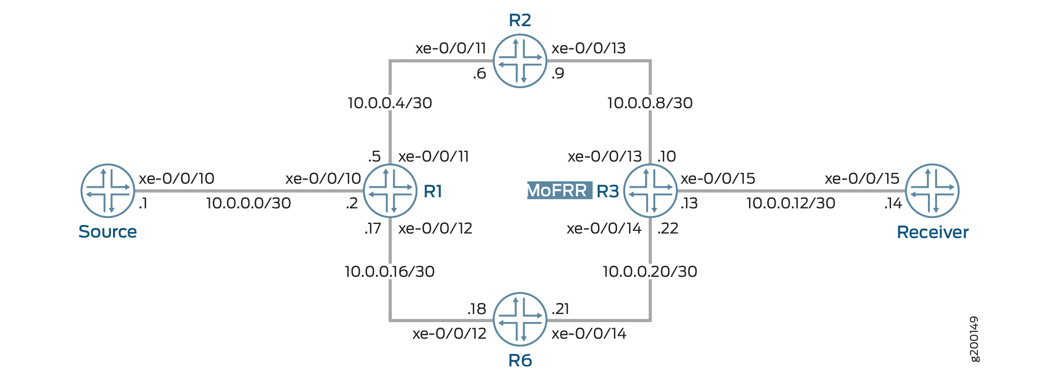
In this example, Device R3 is the egress edge device. MoFRR is enabled on this device only.
OSPF or IS-IS is used for connectivity, though any interior gateway protocol (IGP) or static routes can be used.
PIM sparse mode version 2 is enabled on all devices in the PIM domain. Device R1 serves as the rendezvous point (RP).
Device R3, in addition to MoFRR, also has PIM join load balancing enabled.
For testing purposes, routing or switching devices are used
to simulate the multicast source and the receiver. Device R3 is configured
to statically join the desired group by using the set protocols
igmp interface xe-0/0/15.0 static group 225.1.1.1 command. It
is just joining, not listening. The xe-0/0/15.0 interface is the Device
R3 interface facing the receiver. In the case when a real multicast
receiver host is not available, as in this example, this static IGMP
configuration is useful. On the receiver, to listen to the multicast
group address, this example uses set protocols sap listen 225.1.1.1. For the source to send multicast traffic, a multicast ping is issued
from the source device. The ping command is ping 225.1.1.1 bypass-routing
interface xe-0/0/10.0 ttl 10 count 1000000000. The xe-0/0/10.0
interface is the source interface facing Device R1.
MoFRR configuration includes multiple options that are not shown in this example, but are explained separately. The options are as follows:
stream-protection {
    mofrr-asm-starg;
    mofrr-disjoint-upstream-only;
    mofrr-no-backup-join;
    mofrr-primary-path-selection-by-routing;
    policy policy-name;
}
Topology
Figure 1 shows the sample network.
CLI Quick Configuration shows the configuration for all of the devices in Figure 1.
The section Step-by-Step Configuration describes the steps on Device R3.
CLI Quick Configuration
CLI Quick Configuration
To quickly configure this
example, copy the following commands, paste them into a text file,
remove any line breaks, change any details necessary to match your
network configuration, and then copy and paste the commands into the
CLI at the [edit] hierarchy level.
Device R1
set interfaces xe-0/0/10 unit 0 family inet address 10.0.0.2/30
set interfaces xe-0/0/11 unit 0 family inet address 10.0.0.5/30
set interfaces xe-0/0/12 unit 0 family inet address 10.0.0.17/30
set interfaces lo0 unit 0 family inet address 192.168.0.1/32
set protocols ospf area 0.0.0.0 interface xe-0/0/10.0
set protocols ospf area 0.0.0.0 interface xe-0/0/11.0
set protocols ospf area 0.0.0.0 interface lo0.0 passive
set protocols ospf area 0.0.0.0 interface xe-0/0/12.0
set protocols pim rp local family inet address 192.168.0.1
set protocols pim interface all mode sparse
set protocols pim interface all version 2
Device R2
set interfaces xe-0/0/11 unit 0 family inet address 10.0.0.6/30
set interfaces xe-0/0/13 unit 0 family inet address 10.0.0.9/30
set interfaces lo0 unit 0 family inet address 192.168.0.2/32
set protocols ospf area 0.0.0.0 interface xe-0/0/11.0
set protocols ospf area 0.0.0.0 interface xe-0/0/13.0
set protocols ospf area 0.0.0.0 interface lo0.0 passive
set protocols pim rp static address 192.168.0.1
set protocols pim interface all mode sparse
set protocols pim interface all version 2
Device R3
set interfaces xe-0/0/13 unit 0 family inet address 10.0.0.10/30
set interfaces xe-0/0/15 unit 0 family inet address 10.0.0.13/30
set interfaces xe-0/0/14 unit 0 family inet address 10.0.0.22/30
set interfaces lo0 unit 0 family inet address 192.168.0.3/32
set protocols igmp interface xe-0/0/15.0 static group 225.1.1.1
set protocols ospf area 0.0.0.0 interface xe-0/0/13.0
set protocols ospf area 0.0.0.0 interface xe-0/0/15.0
set protocols ospf area 0.0.0.0 interface lo0.0 passive
set protocols ospf area 0.0.0.0 interface xe-0/0/14.0
set protocols pim rp static address 192.168.0.1
set protocols pim interface all mode sparse
set protocols pim interface all version 2
set protocols pim join-load-balance automatic
set policy-options policy-statement load-balancing-policy then load-balance per-packet
set routing-options forwarding-table export load-balancing-policy
set routing-options multicast stream-protection
Device R6
set interfaces xe-0/0/12 unit 0 family inet address 10.0.0.18/30
set interfaces xe-0/0/14 unit 0 family inet address 10.0.0.21/30
set interfaces lo0 unit 0 family inet address 192.168.0.6/32
set protocols ospf area 0.0.0.0 interface xe-0/0/12.0
set protocols ospf area 0.0.0.0 interface xe-0/0/14.0
set protocols ospf area 0.0.0.0 interface lo0.0 passive
set protocols pim rp static address 192.168.0.1
set protocols pim interface all mode sparse
set protocols pim interface all version 2
Device Source
set interfaces xe-0/0/10 unit 0 family inet address 10.0.0.1/30
set interfaces lo0 unit 0 family inet address 192.168.0.4/32
set protocols ospf area 0.0.0.0 interface xe-0/0/10.0
set protocols ospf area 0.0.0.0 interface lo0.0 passive
Device Receiver
set interfaces xe-0/0/15 unit 0 family inet address 10.0.0.14/30
set interfaces lo0 unit 0 family inet address 192.168.0.5/32
set protocols sap listen 225.1.1.1
set protocols ospf area 0.0.0.0 interface xe-0/0/15.0
set protocols ospf area 0.0.0.0 interface lo0.0 passive
Step-by-Step Configuration
Procedure
Step-by-Step Procedure
The following example requires that you navigate various levels in the configuration hierarchy. For information about navigating the CLI, see Using the CLI Editor in Configuration Mode in the Junos OS CLI User Guide.
To configure Device R3:
Configure the device interfaces.
[edit interfaces]
user@R3# set xe-0/0/13 unit 0 family inet address 10.0.0.10/30
user@R3# set xe-0/0/15 unit 0 family inet address 10.0.0.13/30
user@R3# set xe-0/0/14 unit 0 family inet address 10.0.0.22/30
user@R3# set lo0 unit 0 family inet address 192.168.0.3/32
For testing purposes only, on the interface facing the device labeled Receiver, simulate IGMP joins.
If your test environment has receiver hosts, this step is not necessary.
[edit protocols igmp interface xe-0/0/15.0]
user@R3# set static group 225.1.1.1
Configure IGP or static routes.
[edit protocols ospf area 0.0.0.0]
user@R3# set interface xe-0/0/13.0
user@R3# set interface xe-0/0/15.0
user@R3# set interface lo0.0 passive
user@R3# set interface xe-0/0/14.0
Configure PIM.
[edit protocols pim]
user@R3# set rp static address 192.168.0.1
user@R3# set interface all mode sparse
user@R3# set interface all version 2
(Optional) Configure PIM join load balancing.
[edit protocols pim]
user@R3# set join-load-balance automatic
(Optional) Configure per-packet load balancing.
[edit policy-options policy-statement load-balancing-policy]
user@R3# set then load-balance per-packet
[edit routing-options forwarding-table]
user@R3# set export load-balancing-policy
Enable MoFRR.
[edit routing-options multicast]
user@R3# set stream-protection
Results
From configuration mode, confirm your configuration
by entering the show interfaces, show protocols, show policy-options, and show routing-options commands. If the output does not display
the intended configuration, repeat the instructions in this example
to correct the configuration.
user@R3# show interfaces
xe-0/0/13 {
    unit 0 {
        family inet {
            address 10.0.0.10/30;
        }
    }
}
xe-0/0/14 {
    unit 0 {
        family inet {
            address 10.0.0.22/30;
        }
    }
}
xe-0/0/15 {
    unit 0 {
        family inet {
            address 10.0.0.13/30;
        }
    }
}
lo0 {
    unit 0 {
        family inet {
            address 192.168.0.3/32;
        }
    }
}
user@R3# show protocols
igmp {
    interface xe-0/0/15.0 {
        static {
            group 225.1.1.1;
        }
    }
}
ospf {
    area 0.0.0.0 {
        interface xe-0/0/13.0;
        interface xe-0/0/15.0;
        interface lo0.0 {
            passive;
        }
        interface xe-0/0/14.0;
    }
}
pim {
    rp {
        static {
            address 192.168.0.1;
        }
    }
    interface all {
        mode sparse;
        version 2;
    }
    join-load-balance {
        automatic;
    }
}
user@R3# show policy-options
policy-statement load-balancing-policy {
    then {
        load-balance per-packet;
    }
}
user@R3# show routing-options
forwarding-table {
    export load-balancing-policy;
}
multicast {
    stream-protection;
}
If you are done configuring the device, enter commit from configuration mode.
Verification
Confirm that the configuration is working properly.
- Sending Multicast Traffic Into the PIM Domain
- Verifying the Upstream Interfaces
- Checking the Multicast Routes
Sending Multicast Traffic Into the PIM Domain
Purpose
Use a multicast ping command to simulate multicast traffic.
Action
user@Source> ping 225.1.1.1 bypass-routing interface xe-0/0/10.0 ttl 10 count 1000000000

PING 225.1.1.1 (225.1.1.1): 56 data bytes
64 bytes from 10.0.0.14: icmp_seq=1 ttl=61 time=0.845 ms
64 bytes from 10.0.0.14: icmp_seq=2 ttl=61 time=0.661 ms
64 bytes from 10.0.0.14: icmp_seq=3 ttl=61 time=0.615 ms
64 bytes from 10.0.0.14: icmp_seq=4 ttl=61 time=0.640 ms
Meaning
The interface on Device Source, facing Device R1, is
xe-0/0/10.0. Keep in mind that multicast pings have a TTL of 1 by
default, so you must use the ttl option.
Verifying the Upstream Interfaces
Purpose
Make sure that the egress device has two upstream interfaces for the multicast group join.
Action
user@R3> show pim join 225.1.1.1 extensive sg
Instance: PIM.master Family: INET
R = Rendezvous Point Tree, S = Sparse, W = Wildcard

Group: 225.1.1.1
    Source: 10.0.0.1
    Flags: sparse,spt
    Active upstream interface: xe-0/0/13.0
    Active upstream neighbor: 10.0.0.9
    MoFRR Backup upstream interface: xe-0/0/14.0
    MoFRR Backup upstream neighbor: 10.0.0.21
    Upstream state: Join to Source, No Prune to RP
    Keepalive timeout: 354
    Uptime: 00:00:06
    Downstream neighbors:
        Interface: xe-0/0/15.0
            10.0.0.13 State: Join Flags: S   Timeout: Infinity
            Uptime: 00:00:06 Time since last Join: 00:00:06
    Number of downstream interfaces: 1
Meaning
The output shows an active upstream interface and neighbor, and also an MoFRR backup upstream interface and neighbor.
Checking the Multicast Routes
Purpose
Examine the IP multicast forwarding table to make sure that there is an upstream RPF interface list, with a primary and a backup interface.
Action
user@R3> show multicast route extensive

Instance: master Family: INET

Group: 225.1.1.1
    Source: 10.0.0.1/32
    Upstream rpf interface list:
        xe-0/0/13.0 (P) xe-0/0/14.0 (B)
    Downstream interface list:
        xe-0/0/15.0
    Session description: Unknown
    Forwarding statistics are not available
    RPF Next-hop ID: 836
    Next-hop ID: 1048585
    Upstream protocol: PIM
    Route state: Active
    Forwarding state: Forwarding
    Cache lifetime/timeout: 171 seconds
    Wrong incoming interface notifications: 0
    Uptime: 00:03:09
Meaning
The output shows an upstream RPF interface list, with a primary and a backup interface.