ON THIS PAGE
PCEP Configuration
PCEP Overview
A Path Computation Element (PCE) is an entity (component, application, or network node) that is capable of computing a network path or route based on a network graph and applying computational constraints. A Path Computation Client (PCC) is any client application requesting a path computation to be performed by a PCE. The Path Computation Element Protocol (PCEP) enables communications between a PCC and a PCE, or between two PCEs (defined in RFC 5440).
PCEP is a TCP-based protocol defined by the IETF PCE Working Group, and defines a set of messages and objects used to manage PCEP sessions and to request and send paths for multidomain traffic engineered LSPs (TE LSPs). It provides a mechanism for a PCE to perform path computation for a PCC’s external LSPs. The PCEP interactions include LSP status reports sent by the PCC to the PCE, and PCE updates for the external LSPs.
Figure 1 illustrates the role of PCEP in the client-side implementation of a stateful PCE architecture in an MPLS RSVP-TE enabled network.
A TCP-based PCEP session connects a PCC to an external PCE. The PCC initiates the PCEP session and stays connected to the PCE for the duration of the PCEP session. During the PCEP session, the PCC requests LSP parameters from the stateful PCE. On receiving one or more LSP parameters from the PCE, the PCC re-signals the TE LSP. When the PCEP session is terminated, the underlying TCP connection is closed immediately, and the PCC attempts to re-establish the PCEP session.
Thus, the PCEP functions include:
LSP tunnel state synchronization between a PCC and a stateful PCE—When an active stateful PCE connection is detected, a PCC tries to delegate all LSPs to this PCE in a procedure called LSP state synchronization. PCEP enables synchronization of the PCC LSP state to the PCE.
Delegation of control over LSP tunnels to a stateful PCE—An active stateful PCE controls one or more LSP attributes for computing paths, such as bandwidth, path (ERO), and priority (setup and hold). PCEP enables such delegation of LSPs for path computation.
Stateful PCE control of timing and sequence of path computations within and across PCEP sessions–An active stateful PCE modifies one or more LSP attributes, such as bandwidth, path (ERO), and priority (setup and hold). PCEP communicates these new LSP attributes from the PCE to the PCC, after which the PCC re-signals the LSP in the specified path.
Support of the Path Computation Element Protocol for RSVP-TE Overview
- Understanding MPLS RSVP-TE
- Current MPLS RSVP-TE Limitations
- Use of an External Path Computing Entity
- Components of External Path Computing
- Interaction Between a PCE and a PCC Using PCEP
- LSP Behavior with External Computing
- Configuration Statements Supported for External Computing
- PCE-Controlled LSP Protection
- PCE-Controlled LSP ERO
- PCE-Controlled Point-to-Multipoint RSVP-TE LSPs
- PCE-Initiated Point-to-Point LSPs
- PCE-Initiated Bypass LSP
- PCE-Initiated Point-to-Multipoint LSPs
- SRv6 LSP in PCEP
- Benefits of SRv6 LSPs in PCEP
- Auto-Bandwidth and PCE-Controlled LSP
- TCP-MD5 Authentication for PCEP Sessions
- Impact of Client-Side PCE Implementation on Network Performance
Understanding MPLS RSVP-TE
Traffic engineering (TE) deals with performance optimization of operational networks, mainly mapping traffic flows onto an existing physical topology. Traffic engineering provides the ability to move traffic flow away from the shortest path selected by the interior gateway protocol (IGP) and onto a potentially less congested physical path across a network.
For traffic engineering in large, dense networks, MPLS capabilities can be implemented because they potentially provide most of the functionality available from an overlay model, in an integrated manner, and at a lower cost than the currently competing alternatives. The primary reason for implementing MPLS traffic engineering is to control paths along which traffic flows through a network. The main advantage of implementing MPLS traffic engineering is that it provides a combination of the traffic engineering capabilities of ATM, along with the class-of-service (CoS) differentiation of IP.
In an MPLS network, data plane information is forwarded using label switching. A packet arriving on a provider edge (PE) router from the customer edge (CE) router has labels applied to it, and it is then forwarded to the egress PE router. The labels are removed at the egress router and it is then forwarded out to the appropriate destination as an IP packet. The label-switching routers (LSRs) in the MPLS domain use label distribution protocols to communicate the meaning of labels used to forward traffic between and through the LSRs. RSVP-TE is one such label distribution protocol that enables an LSR peer to learn about the label mappings of other peers.
When both MPLS and RSVP are enabled on a router, MPLS becomes a client of RSVP. The primary purpose of the Junos OS RSVP software is to support dynamic signaling within label-switched paths (LSPs). RSVP reserves resources, such as for IP unicast and multicast flows, and requests quality-of-service (QoS) parameters for applications. The protocol is extended in MPLS traffic engineering to enable RSVP to set up LSPs that can be used for traffic engineering in MPLS networks.
When MPLS and RSVP are combined, labels are associated with RSVP flows. Once an LSP is established, the traffic through the path is defined by the label applied at the ingress node of the LSP. The mapping of label to traffic is accomplished using different criteria. The set of packets that are assigned the same label value by a specific node belong to the same forwarding equivalence class (FEC), and effectively define the RSVP flow. When traffic is mapped onto an LSP in this way, the LSP is called an LSP tunnel.
LSP tunnels are a way to establish unidirectional label-switched paths. RSVP-TE builds on the RSVP core protocol by defining new objects and modifying existing objects used in the PATH and RESV objects for LSP establishment. The new objects—LABEL-REQUEST object (LRO), RECORD-ROUTE object (RRO), LABEL object, and EXPLICIT-ROUTE object (ERO)—are optional with respect to the RSVP protocol, except for the LRO and LABEL objects, which are both mandatory for establishing LSP tunnels.
In general, RSVP-TE establishes a label-switched path that ensures frame delivery from ingress to egress router. However, with the new traffic engineering capabilities, the following functions are supported in an MPLS domain:
-
Possibility to establish a label-switched path using either a full or partial explicit route (RFC 3209).
-
Constraint-based LSP establishment over links that fulfill requirements, such as bandwidth and link properties.
-
Endpoint control, which is associated with establishing and managing LSP tunnels at the ingress and egress routers.
-
Link management, which manages link resources to do resource-aware routing of traffic engineering LSPs and to program MPLS labels.
-
MPLS fast reroute (FRR), which manages the LSPs that need protection and assigns backup tunnel information to these LSPs.
Current MPLS RSVP-TE Limitations
Although the RSVP extensions for traffic engineering enable better network utilization and meet requirements of classes of traffic, today’s MPLS RSVP-TE protocol suite has several issues inherent to its distributed nature. This causes a number of issues during contention for bisection capacity, especially within an LSP priority class where a subset of LSPs share common setup and hold priority values. The limitations of RSVP-TE include:
-
Lack of visibility of individual per-LSP, per-device bandwidth demands—The ingress routers in an MPLS RSVP-TE network establish LSPs without having a global view of the bandwidth demand on the network. Information about network resource utilization is only available as total reserved capacity by traffic class on a per interface basis. Individual LSP state is available locally on each label edge router (LER) for its own LSPs only. As a result, a number of issues related to demand pattern arise, particularly within a common setup and hold priority.
-
Asynchronous and independent nature of RSVP signaling—In RSVP-TE, the constraints for path establishment are controlled by an administrator. As such, bandwidth reserved for an LSP tunnel is set by the administrator and does not automatically imply any limit on the traffic sent over the tunnel. Therefore, bandwidth available on a traffic engineering link is the bandwidth configured for the link, excluding the sum of all reservations made on the link. Thus, the unsignaled demands on an LSP tunnel lead to service degradation of the LSP requiring excess bandwidth, as well as the other LSPs that comply with the bandwidth requirements of the traffic engineering link.
-
LSPs established based on dynamic or explicit path options in the order of preference—The ingress routers in an MPLS RSVP-TE network establish LSPs for demands based on the order of arrival. Because the ingress routers do not have a global view of the bandwidth demand on the network, using the order of preference to establish LSPs can cause traffic to be dropped or LSPs not being established at all when there is an excess of bandwidth demand.
As an example, Figure 2 is configured with MPLS RSVP-TE, in which A and G are the label edge routers (LERs). These ingress routers establish LSPs independently based on the order of demands and have no knowledge or control over each other’s LSPs. Routers B, C, and D are intermediate or transit routers that connect to the egress routers E and F.
The ingress routers establish LSPs based on the order in which the demands arrive. If Router G receives two demands of capacity 5 each for G-F, then G signals two LSPs – LSP1 and LSP2 – through G-B-D-F. In the same way, when Router A receives the third demand of capacity 10 for A-E, then it signals an LSP, LSP3, through A-B-C-E. However, if the demand on the A-E LSP increases from 10 to 15, Router A cannot signal LSP3 using the same (A-B-C-E) path, because the B-C link has a lower capacity.
Router A should have signaled the increased demand on LSP3 using the A-B-D-C-E path. Since LSP1 and LSP2 have utilized the B-D link based on the order of demands received, LSP3 is not signaled.
Thus, although adequate max-flow bandwidth is available for all the LSPs, LSP3 is subject to potentially prolonged service degradation. This is due to Router A’s lack of global demand visibility and the lack of systemic coordination in demand placement by the ingress routers A and G.
Use of an External Path Computing Entity
As a solution to the current limitations found in the MPLS RSVP-TE path computation, an external path computing entity with a global view of per-LSP, per-device demand in the network independent of available capacity is required.
Currently, only online and real-time constraint-based routing path computation is provided in an MPLS RSVP-TE network. Each router performs constraint-based routing calculations independent of the other routers in the network. These calculations are based on currently available topology information—information that is usually recent, but not completely accurate. LSP placements are locally optimized, based on current network status. The MPLS RSVP-TE tunnels are set up using the CLI. An operator configures the TE LSP, which is then signaled by the ingress router.
In addition to the existing traffic engineering capabilities, the MPLS RSVP-TE functionality is extended to include an external path computing entity, called the Path Computation Element (PCE). The PCE computes the path for the TE LSPs of ingress routers that have been configured for external control. The ingress router that connects to a PCE is called a Path Computation Client (PCC). The PCC is configured with the Path Computation Client Protocol (PCEP) to facilitate external path computing by a PCE.
For more information, see Components of External Path Computing.
To enable external path computing for a PCC’s TE LSPs, include the
lsp-external-controller pccd statement at the [edit
mpls] and [edit mpls lsp lsp-name] hierarchy
levels.
Components of External Path Computing
The components that make up an external path computing system are:
Path Computation Element
A Path Computation Element (PCE) can be any entity (component, application, or network node) that is capable of computing a network path or route based on a network graph and applying computational constraints. However, a PCE can compute the path for only those TE LSPs of a PCC that have been configured for external control.
A PCE can either be stateful or stateless.
-
Stateful PCE—A stateful PCE maintains strict synchronization between the PCE and network states (in terms of topology and resource information), along with the set of computed paths and reserved resources in use in the network. In other words, a stateful PCE utilizes information from the traffic engineering database as well as information about existing paths (for example, TE LSPs) in the network when processing new requests from the PCC.
A stateful PCE is of two types:
-
Passive stateful PCE—Maintains synchronization with the PCC and learns the PCC LSP states to better optimize path calculations, but does not have control over them.
-
Active stateful PCE—Actively modifies the PCC LSPs, in addition to learning about the PCC LSP states.
Note:In a redundant configuration with main and backup active stateful PCEs, the backup active stateful PCE cannot modify the attributes of delegated LSPs until it becomes the main PCE at the time of a failover. There is no preempting of PCEs in the case of a switchover. The main PCE is backed by a backup PCE, and when the main PCE goes down, the backup PCE assumes the role of the main PCE and remains the main PCE even after the PCE that was previously the main PCE is operational again.
A stateful PCE provides the following functions:
-
Offers offline LSP path computation.
-
Triggers LSP re-route when there is a need to re-optimize the network.
-
Changes LSP bandwidth when there is an increase in bandwidth demand from an application.
-
Modifies other LSP attributes on the router, such as ERO, setup priority, and hold priority.
A PCE has a global view of the bandwidth demand in the network and maintains a traffic-engineered database to perform path computations. It performs statistics collection from all the routers in the MPLS domain using SNMP and NETCONF. This provides a mechanism for offline control of the PCC’s TE LSPs. Although an offline LSP path computation system can be embedded in a network controller, the PCE acts like a full-fledged network controller that provides control over the PCC’s TE LSPs, in addition to computing paths.
Although a stateful PCE allows for optimal path computation and increased path computation success, it requires reliable state synchronization mechanisms, with potentially significant control plane overhead and the maintenance of a large amount of data in terms of states, as in the case of a full mesh of TE LSPs.
-
-
Stateless PCE—A stateless PCE does not remember any computed path, and each set of requests is processed independently of each other (RFC 5440).
Path Computation Client
A Path Computation Client (PCC) is any client application requesting a path computation to be performed by a PCE.
A PCC can connect to a maximum of 10 PCEs at one time. The PCC to PCE connection can be a configured static route or a TCP connection that establishes reachability. The PCC assigns each connected PCE a priority number. It sends a message to all the connected PCEs with information about its current LSPs, in a process called LSP state synchronization. For the TE LSPs that have external control enabled, the PCC delegates those LSPs to the main PCE. The PCC elects, as the main PCE, a PCE with the lowest priority number, or the PCE that it connects to first in the absence of a priority number.
The PCC re-signals an LSP based on the computed path it receives from a PCE. When the PCEP session with the main PCE is terminated, the PCC elects a new main PCE, and all delegated LSPs to the previously main PCE are delegated to the newly available main PCE.
Path Computation Element Protocol
The Path Computation Element Protocol (PCEP) is used for communication between PCC and PCE (as well as between two PCEs) (RFC 5440). PCEP is a TCP-based protocol defined by the IETF PCE Working Group, and defines a set of messages and objects used to manage PCEP sessions and to request and send paths for multidomain TE LSPs. The PCEP interactions include PCC messages, as well as notifications of specific states related to the use of a PCE in the context of MPLS RSVP-TE. When PCEP is used for PCE-to-PCE communication, the requesting PCE assumes the role of a PCC.
Thus, the PCEP functions include:
-
LSP tunnel state synchronization between PCC and a stateful PCE.
-
Delegation of control over LSP tunnels to a stateful PCE.
Interaction Between a PCE and a PCC Using PCEP
Figure 3 illustrates the relationship between a PCE, PCC, and the role of PCEP in the context of MPLS RSVP-TE.
The PCE to PCC communication is enabled by the TCP-based PCEP. The PCC initiates the PCEP session and stays connected to a PCE for the duration of the PCEP session.
Starting with Junos OS Release 16.1, you can secure a PCEP session using TCP-MD5
authentication as per RFC 5440. To enable the MD5 security mechanism for a PCEP session, it is
recommended that you define and bind the MD5 authentication key at the [edit protocols
pcep pce pce-id] hierarchy level for a PCEP session. You can,
however, also use a predefined keychain from the [edit security
authentication-key-chains key-chain] hierarchy level to secure a
PCEP session. In this case, you should bind the predefined keychain into the PCEP session at
the [edit protocols pcep pce pce-id] hierarchy level.
The PCE and PCC use the same key to verify the authenticity of each segment sent on the TCP connection of the PCEP session, thereby securing the PCEP communication between the devices, which might be subject to attacks and can disrupt services on the network.
For more information on securing PCEP sessions using MD5 authentication, see TCP-MD5 Authentication for PCEP Sessions.
Once the PCEP session is established, the PCC performs the following tasks:
-
LSP state synchronization—The PCC sends information about all the LSPs (local and external) to all connected PCEs. For external LSPs, the PCC sends information about any configuration change, RRO change, state change, and so on, to the PCE.
For PCE-initiated LSPs, there is no LSP configuration present on the PCC. The PCE initiating the LSP sends the LSP parameters to the PCC that has indicated its capability of supporting PCE-initiated LSPs.
Note:Support for PCE-initiated LSPs is provided in Junos OS Release 13.3 and later releases.
-
LSP delegation—After the LSP state information is synchronized, the PCC then delegates the external LSPs to one PCE, which is the main active stateful PCE. Only the main PCE can set parameters for the external LSP. The parameters that the main PCE modifies include bandwidth, path (ERO), and priority (setup and hold). The parameters specified in the local configuration are overridden by the parameters that are set by the main PCE.
Note:When the PCEP session with the main PCE is terminated, the PCC elects a new main PCE, and all delegated LSPs to the previously main PCE are delegated to the newly available main PCE.
In the case of PCE-initiated LSPs, the PCC creates the LSP using the parameters received from the PCE. The PCC assigns the PCE-initiated LSP a unique LSP-ID, and automatically delegates the LSP to the PCE. A PCC cannot revoke the delegation for the PCE-initiated LSPs for an active PCEP session.
When a PCEP session terminates, the PCC starts two timers without immediately deleting the PCE-initiated LSPs –
delegation cleanup timeoutandlsp cleanup timer– to avoid disruption of services. During this time, an active stateful PCE can acquire control of the LSPs provisioned by the failed PCE, by sending a create request for the LSP.Control over PCE-initiated LSPs reverts to the PCC at the expiration of the
delegation cleanup timeout. When thedelegation cleanup timeoutexpires, and no other PCE has acquired control over the LSP from the failed PCE, the PCC takes local control of the non-delegated PCE-initiated LSP. Later, when the original or a new active stateful PCE wishes to acquire control of the locally controlled PCE-initiated LSPs, the PCC delegates these LSPs to the PCE and thelsp cleanup timertimer is stopped.A PCE may return the delegation of the PCE-initiated LSP to the PCC to allow LSP transfer between PCEs. This triggers the
lsp cleanup timerfor the PCE-initiated LSP. The PCC waits for the LSP cleanup timer to expire before removing the non-delegated PCE-initiated LSPs from the failed PCE.When the
lsp cleanup timerexpires, and no other PCE has acquired control over the LSPs from the failed PCE, the PCC deletes all the LSPs provisioned by the failed PCE.Note:In compliance with draft-ietf-pce-stateful-pce-09, revoking of PCE-initiated LSP delegations by a PCC happens in a make-before-break fashion before the LSPs are redelegated to an alternate PCE. Starting in Junos OS Release 18.1R1, the
lsp-cleanup-timermust be greater than or equal to thedelegation-cleanup-timeoutfor the PCC to revoke the LSP delegations. If not, the redelegation timeout interval for the PCC can be set to infinity, where the LSP delegations to that PCE remain intact until specific action is taken by the PCC to change the parameters set by the PCE. -
LSP signaling—On receiving one or more LSP parameters from the main active stateful PCE, the PCC re-signals the TE LSP based on the PCE provided path. If the PCC fails to set up the LSP, it notifies the PCE of the setup failure and waits for the main PCE to provide new parameters for that LSP, and then re-signals it.
When the PCE specifies a path that is incomplete or has loose hops where only the path endpoints are specified, the PCC does not perform local constraint-based routing to find out the complete set of hops. Instead, the PCC provides RSVP with the PCE provided path, as it is, for signaling, and the path gets set up using IGP hop-by-hop routing.
Considering the topology used in Figure 2, Figure 4 illustrates the partial client-side PCE implementation in the MPLS RSVP-TE enabled network. The ingress routers A and G are the PCCs that are configured to connect to the external stateful PCE through a TCP connection.
The PCE has a global view of the bandwidth demand in the network and performs external path computations after looking up the traffic engineering database. The active stateful PCE then modifies one or more LSP attributes and sends an update to the PCC. The PCC uses the parameters it receives from the PCE to re-signal the LSP.
This way, the stateful PCE provides a cooperative operation of distributed functionality used to address specific challenges of a shortest interdomain constrained path computation. It eliminates congestion scenarios in which traffic streams are inefficiently mapped onto available resources, causing overutilization of some subsets of network resources, while other resources remain underutilized.
LSP Behavior with External Computing
LSP Types
In a client-side PCE implementation, there are three types of TE LSPs:
-
CLI-controlled LSPs—The LSPs that do not have the
lsp-external-controller pccdstatement configured are called CLI-controlled LSPs. Although these LSPs are under local control, the PCC updates the connected PCEs with information about the CLI-controlled LSPs during the initial LSP synchronization process. After the initial LSP synchronization, the PCC informs the PCE of any new and deleted LSPs as well. -
PCE-controlled LSPs—The LSPs that have the
lsp-external-controller pccdstatement configured are called PCE-controlled LSPs. The PCC delegates the PCC-initiated LSPs to the main PCE for external path computation.The PCC informs the PCE about the configured parameters of a PCE-controlled LSP, such as bandwidth, ERO, and priorities. It also informs the PCE about the actual values used for these parameters to set up the LSP including the RRO, when available.
The PCC sends such LSP status reports to the PCE only when a reconfiguration has occurred or when there is a change in the ERO, RRO, or status of the PCE-controlled LSPs under external control.
There are two types of parameters that come from the CLI configuration of an LSP for a PCE:
-
Parameters that are not overridden by a PCE, and that are applied immediately.
-
Parameters that are overridden by a PCE. These parameters include bandwidth, path, and priority (setup and hold values). When the control mode switches from external to local, the CLI-configured values for these parameters are applied at the next opportunity to re-signal the LSP. The values are not applied immediately.
-
-
Externally-provisioned LSPs (or PCE-initiated LSPs)—The LSPs that have the
lsp-provisioningstatement configured are called PCE-initiated LSPs. A PCE-initiated LSP is dynamically created by an external PCE; as a result, there is no LSP configuration present on the PCC. The PCC creates the PCE-initiated LSP using the parameters provided by the PCE, and automatically delegates the LSP to the PCE.Note:Support for PCE-initiated LSPs is provided in Junos OS Release 13.3 and later releases.
The CLI-controlled LSPs, PCE-controlled LSPs, and PCE-initiated LSPs can coexist on a PCC.
The CLI-controlled LSPs and PCE-controlled LSPs can coexist on a PCC.
LSP Control Mode
In a client-side PCE implementation, there are two types of control modes for a PCC-controlled LSP:
-
External—By default, all PCE-controlled LSPs are under external control. When an LSP is under external control, the PCC uses the PCE-provided parameters to set up the LSP.
-
Local—A PCE-controlled LSP can come under local control. When the LSP switches from external control to local control, path computation is done using the CLI-configured parameters and constraint-based routing. Such a switchover happens only when there is a trigger to re-signal the LSP. Until then, the PCC uses the PCE-provided parameters to signal the PCE-controlled LSP, although the LSP remains under local control.
A PCE-controlled LSP switches to local control from its default external control mode in cases such as no connectivity to a PCE or when a PCE returns delegation of LSPs back to the PCC.
For more information about CLI-controlled LSPs and PCE-controlled LSPs, see LSP Types.
Configuration Statements Supported for External Computing
Table 1 lists the MPLS and existing LSP configuration statements that apply to a PCE-controlled LSP.
|
Support for PCE-Controlled LSP |
Applicable LSP Configuration Statements |
Applicable MPLS Configuration Statements |
|---|---|---|
|
These configuration statements can be configured along with the PCE configuration. However, they take effect only when the local configuration is in use. During PCE control, these configuration statements remain inactive. |
|
|
|
These configuration statements can be configured along with the PCE configuration, but are overridden by the PCE-controlled LSP attributes. However, when the local configuration is in use, the configured values for these configuration statements are applied. Note:
Changes to the local configuration using the CLI while the LSP is under the control of a stateful PCE do not have any effect on the LSP. These changes come into effect only when the local configuration is applied. |
|
|
|
These configuration statements cannot be configured along with the PCE configuration. |
|
|
The rest of the LSP configuration statements are applicable in the same way as for existing LSPs. On configuring any of the above configuration statements for a PCE-controlled LSP, an MPLS log message is generated to indicate when the configured parameters take effect.
PCE-Controlled LSP Protection
The protection paths, including fast reroute and bypass LSPs, are locally computed by the PCC using constraint-based routing. A stateful PCE specifies the primary path (ERO) only. A PCE can also trigger a non-standby secondary path, even if the local configuration does not have a non-standby secondary path for LSP protection.
PCE-Controlled LSP ERO
For PCE-controlled LSPs (PCC-delegated LSPs and PCE-initated LSPs), only a full-blown Explicit Route Object (ERO) object has to be sent from the PCE to the PCC; otherwise the PCC rejects the PCUpdate or PCCreate message for that PCEP session.
Starting in Junos OS Release 17.2, in addition to external cspf, two new path
computation types are introduced for the PCE-controlled LSPs: local cspf and
no cspf.
-
local cspf—A PCC uses thelocal cspfcomputation type only when the PCE sends in a Juniper Vendor TLV (enterprise number: 0x0a4c) of type 5. -
no cspf—Neither the PCE nor the PCC performs a constrained path calculation. The endpoints and constraints are given to the RSVP module for setting up the LSP with the IGP path.A PCC uses
no cspfcomputation type in the following cases:-
When the PCE sends
local cspfTLV, and when the Junos OS configuration or matching template for this LSP includedno-cspfin the PCC-delegated LSP. -
When the PCE sends
local cspfTLV, and when the Junos OS configuration template for this LSP includedno-cspfin the PCE-initiated LSP. -
When the PCE does not send
local cspfTLV with an empty ERO or loose ERO (with loose bit set in the ERO object).
-
With these new computation types, a PCC can accept an ERO object either as a loose ERO, or as an empty ERO. An external path computing entity that is not capable of computing a path can modify parameters such as bandwidth and color, based on the analytics. In such cases, an empty ERO object or loose ERO is used and the path to be taken is decided by the PCC.
PCE-Controlled Point-to-Multipoint RSVP-TE LSPs
After a PCEP session is established between a PCE and a PCC, the PCC reports all the LSPs in the system to the PCE for LSP state synchronization. This includes PCC-controlled, PCE-delegated, and PCE-initiated point-to-point LSPs. Starting with Junos OS Release 15.1F6 and 16.1R1, this capability is extended to report point-to-multipoint LSPs as well. For a PCE, the point-to-multipoint LSP is similar to that of RSVP point-to-multipoint LSP, where the point-to-multipoint LSP is treated as collection of point-to-point LSPs grouped under a point-to-multipoint identifier.
By default, PCE control of point-to-multipoint LSPs is not supported on a PCC. To add this
capability, include the p2mp-lsp-report-capability statement at the
[edit protocols pcep pce pce-name] or [edit
protocols pcep pce-group group-id] hierarchy levels. After the
point-to-multipoint report capability is configured on a PCC, the PCC advertises this capability
to the PCE. If the PCE advertises the same point-to-multipoint report capability in return, then
the PCC reports the complete point-to-multipoint LSP tree to the PCE for LSP state
synchronization.
A PCC with the point-to-multipoint TE LSP capability supports reporting of point-to-multipoint TE LSPs for stateful PCEs, point-to-multipoint update, and LSP database supporting point-to-multipoint LSP name as key. However, the following features and functions are not supported for Junos OS Release 15.1F6 and 16.1:
-
Static point-to-multipoint LSPs
-
PCE-delegated and PCE-initiated point-to-multipoint LSPs
-
Auto-bandwidth
-
TE++
-
PCE request and reply message
-
Creation of point-to-multipoint LSPs using templates
-
Configuring forward entry on the PCE-initiated point-to-multipoint LSPs
-
Configuring forward entry on the router pointing to a provisioned LSP.
PCE-Initiated Point-to-Point LSPs
Starting with Junos OS Release 16.1, the PCEP functionality is extended to allow a stateful PCE to initiate and provision traffic engineering LSPs through a PCC. Earlier, the LSPs were configured on the PCC and the PCC delegated control over the external LSPs to a PCE. The ownership of the LSP state was maintained by the PCC. With the introduction of the PCE-initiated LSPs, a PCE can initiate and provision a traffic engineering point-to-point LSP dynamically without the need for a locally configured LSP on the PCC. On receiving a PCCreate message from a PCE, the PCC creates the PCE-initiated LSP and automatically delegates the LSP to the PCE.
By default, a PCC rejects the request for provisioning PCE-initiated point-to-point LSPs from
a PCE. To enable support of PCE-initated LSPs on the PCC, include the lsp-provisioning statement at the [edit protocols pcep pce
pce-id] or [edit protocols pcep pce-group
group-id] hierarchy levels.
A PCC indicates its capability of supporting PCE-initiated point-to-point LSPs while establishing the Path Computation Element Protocol (PCEP) session with the PCE. A PCE selects a PCC with this capability to initiate an LSP. The PCE provides the PCC with the PCE-initiated LSP parameters. On receiving the PCE-initiated point-to-point LSP parameters, the PCC sets up the LSP, assigns an LSP ID, and automatically delegates the LSP to the PCE.
When the PCE initiating the LSP does not provide the PCE-initiated point-to-point LSP
parameters, the PCC uses the default parameters. An optional LSP template may also be configured
to specify values for the PCE-initiated point-to-point LSP when the LSP parameters are not
provided by the PCE. To configure an LSP template for PCE-initiated point-to-point LSPs on the
PCC, include the label-switched-path-template statement at the [edit protocols mpls
lsp-external-controller lsp-external-controller] hierarchy
level.
When a PCEP session terminates, the PCC starts two timers without immediately deleting the
PCE-initiatedLSPs—delegation cleanup timeout and lsp cleanup
timer—to avoid disruption of services. During this time, an active stateful PCE can
acquire control of the LSPs provisioned by the failed PCE.
A PCE may return the delegation of the PCE-initiated point-to-point LSP to the PCC to allow LSP transfer between PCEs. Control over PCE-initiated LSPs reverts to the PCC at the expiration of the delegation cleanup timeout. When the delegation cleanup timeout expires, and no other PCE has acquired control over the LSP from the failed PCE, the PCC takes local control of the non-delegated PCE-initiated LSP. Later, when the original or a new active stateful PCE wishes to acquire control of the locally controlled PCE-initiated point-to-point LSPs, the PCC delegates these LSPs to the PCE and the LSP cleanup timer is stopped.
The PCC waits for the LSP cleanup timer to expire before deleting the non-delegated PCE-initiated point-to-point LSPs from the failed PCE. When the LSP cleanup timer expires, and no other PCE has acquired control over the LSPs from the failed PCE, the PCC deletes all the LSPs provisioned by the failed PCE.
Starting in Junos OS Release 21.1R1, we support nonstop active routing (NSR) for PCE-initiated RSVP-based point-to-point and point-to-multipoint LSPs. Only the primary Routing Engine maintains the PCEP session with the controller. It synchronizes all RSVP LSPs initiated by PCEs, including multicast flow specifications for any PCE-initiated P2MP LSPs, with the backup Routing Engine. During a switchover, the PCEP session goes down and re-establishes when the backup Routing Engine becomes the primary Routing Engine. This reduces traffic loss for the traffic carried over PCE-initiated RSVP LSPs during Routing Engine switchovers. This feature is enabled when NSR is configured.
PCE-Initiated Bypass LSP
- Understanding PCE-Initiated Bypass LSPs
- Benefits of PCE-Initiated Bypass LSP
- Behavior of PCE-Initiated Bypass LSPs During PCEP Session Failure
Understanding PCE-Initiated Bypass LSPs
There can be traffic outages at the time of a link or node failure because the backup protection paths in the network do not have sufficient bandwidth to handle traffic. In such networks, although a PCE may be used to compute all the paths, to optimize network performance, the local protection paths also need to be controlled through the PCE.
Junos OS Release 19.2R1 and later releases provide partial support for the Internet draft draft-cbrt-pce-stateful-local-protection-01 (expires December 2018), PCEP Extensions for RSVP-TE Local-Protection with PCE-Stateful, where the PCEP functionality is extended to allow a stateful PCE to initiate, provision, and manage bypass LSPs for a protected interface. Multiple bypass LSPs with bandwidth reservation can be initiated by the PCE to protect a link or node. The bandwidth on the bypass LSP is expected to be smaller than the total bandwidth of the primary LSPs that it might protect.
The existing bypass selection mechanism, that prefers manual bypass LSPs (if available) over dynamic bypass LSPs, is extended to prefer PCE-provisioned bypass LSPs (if available) over dynamic bypass LSPs. The PCE-provisioned bypass LSPs have a higher preference over dynamic bypass LSPs, but are less preferred over manual bypass LSPs.
The set of operations that are used to perform on any operational bypass LSPs, such as
clear rsvp session, can also be performed on the PCE-initiated bypass LSPs.
You can use commands, such as show path-computation-client status extensive
and show path-computation-client lsp to view PCE-initiated bypass LSP
statistics.
With the support of PCE-initiated bypass LSP, you can:
-
Create a RSVP bypass LSP through PCEP from an external controller, where the bypass LSP:
-
can be for link or node protection.
-
must have a non-zero bandwidth.
-
must have a specified strict ERO.
-
-
Update the bandwidth and ERO for an existing PCE-created bypass LSP.
-
Oversubscribe the bypass LSP bandwidth for admission control of primary LSPs. This must be a per-bypass parameter, and should allow updating the subscription per bypass LSP.
Benefits of PCE-Initiated Bypass LSP
The PCE-initiated bypass LSPs provide the following benefits:
-
Better control over traffic after a failure and more deterministic path computation of protection paths.
-
Meet complex constraints and diversity requirements, such as maintaining diverse paths for LSPs, as well as their local protection paths.
-
Ensure links are not overloaded during failure events.
Behavior of PCE-Initiated Bypass LSPs During PCEP Session Failure
At the time of a PCEP session failure, the PCE-initiated bypass LSPs become orphan until the expiration of the state timeout timer. The PCE-initiated bypass LSPs get cleaned up on the expiration of the state timeout timer. To obtain control of a PCE-initiated bypass LSP (after PCEP session fails), a PCE (either the primary PCE, or any secondary PCE) sends a PCInitiate message before the expiration of the state timeout timer.
PCE-Initiated Point-to-Multipoint LSPs
With the introduction of point-to-multipoint PCE-initiated LSPs, a PCE can initiate and provision a point-to-multipoint LSP dynamically without the need for local LSP configuration on the PCC. This enables the PCE to control the timing and sequence of the point-to-multipoint path computations within and across Path Computation Element Protocol (PCEP) sessions, thereby creating a dynamic network that is centrally controlled and deployed.
For more information, see Understanding Path Computation Element Protocol for MPLS RSVP-TE with Support for PCE-Initiated Point-to-Multipoint LSPs.
SRv6 LSP in PCEP
Segment routing can be applied to both MPLS and IPv6 forwarding plane. The Path Computation Element (PCE) computes SR paths for both MPLS and IPv6 forwarding plane. Segment routing for PCEP supports SR LSPs such as PCE-initiated, locally created, and delegated SR LSPs in IPv6 forwarding plane.
Benefits of SRv6 LSPs in PCEP
- Allows you to create PCE initiated SRv6 LSPs.
- Delegate the SRv6 LSPs created on the router to the controller.
- Report the LSPs which are locally created on the router to the controller.
- SRv6 network programming provides the flexibility to leverage segment routing without deploying MPLS.
PCEP supports creation, updation, and deletion of PCE initiated colored and uncolored SRv6 LSPs. When PCE initiated SRv6 LSP co-exists along with a static SRv6 LSP for the same IP or color-based IP, then the static SRv6 TE LSP contributing route is preferred over PCE initiated SRv6 TE LSP contributing route.
To configure a PCEP session to be SRv6 capable, you need to enable the
srv6-capability configuration statement at the [edit protocols pcep pce
pce-id] or at the [edit protocols pcep pce-group pce-id] hierarchy levels. If
the srv6-capability configuration statement is enabled, then you must also
enable srv6 configuration statement at the [edit protocols
source-packet-routing] hierarchy level otherwise during commit and error will be
displayed.
To configure SRv6 for SR-TE, you need to add the srv6 configuration statement at the [edit protocols source-packet-routing] hierarchy level.
[See Understanding SR-TE Policy for SRv6 Tunnel for more information.
To configure the maximum segment list depth for SRv6 LSP, you need to enable the
maximum-srv6-segment-list-depth configuration statement at the [edit
protocols pcep] hierarchy level.
Auto-Bandwidth and PCE-Controlled LSP
Starting in Junos OS Release 14.2R4, support of auto-bandwidth is provided for PCE-controlled LSPs. In earlier releases, the auto-bandwidth option did not apply to PCE-controlled LSPs, although LSPs under the control of auto-bandwdith and constraint-based routing could coexist with PCE-controlled LSPs. The statistics collection for auto-bandwidth was taking effect only when the control mode of a PCE-controlled LSP changes from external to local. This was happening in cases such as no connectivity to a PCE or when a PCE returns delegation of LSPs back to the PCC.
TCP-MD5 Authentication for PCEP Sessions
A stateful PCE server automates the creation of traffic engineering paths across the network, increasing network utilization and enabling a customized programmable networking experience with the use of PCEP communication with a PCC. A PCC sends LSP reports to a PCE server, and the PCE updates or provisions LSPs back to the PCC. The data sent over a PCEP session is crucial for a PCE server to perform external path computing. As a result, an attack on the PCEP communication can disrupt network services. If altered PCEP messages are sent to a PCC, inappropriate LSPs can be set up. Similarly, if altered PCEP messages are sent to a PCE, an incorrect view of the network is learned by the PCE.
Considering the significance of the PCEP communication between a PCE and PCC in executing the PCE functionalities effectively, Junos OS Release 16.1 introduces the feature of securing a PCEP session using TCP-MD5 authentication as per RFC 5440. This feature protects the communication between a PCE and PCC over a PCEP session, which might be subject to an attack, and can disrupt network services.
To enable the MD5 security mechanism for a PCEP session, it is recommended that you define and
bind the MD5 authentication key at the [edit protocols pcep pce
pce-id] hierarchy level for a PCEP session. You can, however, also
use a predefined keychain from the [edit security authentication-key-chains
key-chain] hierarchy level to secure a PCEP session. In this case,
you should bind the predefined keychain into the PCEP session at the [edit protocols
pcep pce pce-id] hierarchy level.
The following configuration is executed on the PCC to establish a secure PCEP session with a PCE:
-
Using MD5 authentication key:
[edit protocols pcep pce pce-id] user@PCC# set authentication-key key
-
Using predefined authentication keychain:
[edit protocols pcep pce pce-id] user@PCC# set authentication-key-chain key-chain user@PCC# set authentication-algorithm md5
For secure PCEP sessions to be established successfully, the MD5 authentication should be configured with the pre-shared authentication key on both the PCE server and the PCC. The PCE and PCC use the same key to verify the authenticity of each segment sent on the TCP connection of the PCEP session.
-
Junos OS Release 16.1 supports only TCP-MD5 authentication for PCEP sessions, without extending support for TLS and TCP-AO, such as protection against eavesdropping, tampering, and message forgery.
-
Initial application of security mechanism to a PCEP session causes the session to reset.
-
If MD5 is misconfigured or not configured on one side of the PCEP session, the session does not get established. Verify that the configurations on the PCC and PCE are matching.
-
This feature does not provide support for any session authentication mechanism.
-
To view the authentication keychain used by the PCEP session, use the
show path-computation-client statusandshow protocols pcepcommand outputs. -
Use the
show system statistics tcp | match authcommand to view the number of packets that get dropped by TCP because of authentication errors. -
Operation of the keychain can be verified by using the
show security keychain detailcommand output.
Impact of Client-Side PCE Implementation on Network Performance
The maintenance of a stateful database can be non-trivial. In a single centralized PCE environment, a stateful PCE simply needs to remember all the TE LSPs that the PCE has computed, the TE LSPs that were actually set up (if this can be known), and when the TE LSPs were torn down. However, these requirements cause substantial control protocol overhead in terms of state, network usage and processing, and optimizing links globally across the network. Thus, the concerns of a stateful PCE implementation include:
-
Any reliable synchronization mechanism results in significant control plane overhead. PCEs might synchronize state by communicating with each other, but when TE LSPs are set up using distributed computation performed among several PCEs, the problems of synchronization and race condition avoidance become larger and more complex.
-
Out-of-band traffic engineering database synchronization can be complex with multiple PCEs set up in a distributed PCE computation model, and can be prone to race conditions, scalability concerns, and so on.
-
Path calculations incorporating total network state is highly complex, even if the PCE has detailed information on all paths, priorities, and layers.
In spite of the above concerns, the partial client-side implementation of the stateful PCE is extremely effective in large traffic engineering systems. It provides rapid convergence and significant benefits in terms of optimal resource usage, by providing the requirement for global visibility of a TE LSP state and for ordered control of path reservations across devices within the system being controlled.
Example: Configuring the Path Computation Element Protocol for MPLS RSVP-TE
This example shows how to enable external path computing by a Path Computation Element (PCE) for traffic engineered label-switched paths (TE LSPs) on a Path Computation Client (PCC). It also shows how to configure the Path Computation Element Protocol (PCEP) on the PCC to enable PCE to PCC communication.
Requirements
This example uses the following hardware and software components:
Three routers that can be a combination of ACX Series routers, M Series Multiservice Edge Routers, MX Series 5G Universal Routing Platforms, T Series Core Routers, or PTX Series Transport Router, one of which is configured as a PCC.
A TCP connection to an external stateful PCE from the PCC.
Junos OS Release 12.3 or later running on the PCC along with the JSDN add-on package.
The JSDN add-on package is required to be installed along with the core Junos OS installation package.
Before you begin:
Configure the device interfaces.
Configure MPLS and RSVP-TE.
Configure IS-IS or any other IGP protocol.
Overview
Starting with Junos OS Release 12.3, the MPLS RSVP-TE functionality is extended to provide a partial client-side implementation of the stateful PCE architecture (draft-ietf-pce-stateful-pce) on a PCC.
The partial client-side implementation of the stateful PCE architecture is based on version 2 of Internet draft draft-ietf-pce-stateful-pce. Starting with Junos OS Release 16.1, this implementation is upgraded to support version 7, as defined in Internet draft draft-ietf-pce-stateful-pce-07. Releases prior to 16.1 support the older version of the PCE draft, causing interoperability issues between a PCC running a previous release and a stateful PCE server that adheres to Internet draft draft-ietf-pce-stateful-pce-07.
To enable external path computing by a PCE, include the lsp-external-controller statement on the PCC at the [edit
mpls] and [edit mpls lsp lsp-name] hierarchy levels.
lsp-external-controller pccd;
An LSP configured with the lsp-external-controller statement is referred to as a PCE-controlled LSP and is under the
external control of a PCE by default. An active stateful PCE can override
the parameters set from the CLI, such as bandwidth, path (ERO), and
priority, for such PCE-controlled LSPs of the PCC.
To enable PCE to PCC communication, configure PCEP on the PCC
at the [edit protocols] hierarchy level.
pcep { ... }
When configuring PCEP on a PCC, be aware of the following considerations:
The JSDN add-on package is required to be installed along with the core Junos OS installation package.
Junos OS Release 12.3 supports only stateful PCEs.
A PCC can connect to a maximum of 10 stateful PCEs. At any given point in time, there can be only one main PCE (the PCE with the lowest priority value, or the PCE that connects to the PCC first in the absence of a PCE priority) to which the PCC delegates LSPs for path computation.
For Junos OS Release 12.3, the PCC always initiates the PCEP sessions. PCEP sessions initiated by remote PCEs are not accepted by the PCC.
Existing LSP features, such as LSP protection and make-before-break, work for PCE-controlled LSPs.
The auto-bandwidth option is turned off for PCE-controlled LSPs, although LSPs under the control of auto-bandwdith and constraint-based routing can coexist with PCE-controlled LSPs.
PCE-controlled LSPs can be referred to by other CLI configurations, such as lsp-nexthop to routes, forwarding adjacencies, CCC connections, and logical tunnels.
PCE-controlled LSPs do not support GRES.
PCE-controlled LSPs under logical-systems are not supported.
PCE-controlled LSPs cannot be point-to-multipoint LSPs.
Bidirectional LSPs are not supported.
PCE-controlled LSPs cannot have secondary paths without a primary path.
PCE-controlled LSPs depend on external path computation, which impacts overall setup time, reroutes, and make-before-break features.
Setup time and convergence time (reroute, MBB) for exisiting LSPs is the same as in previous releases, in the absence of PCE-controlled LSPs. However, a small impact is seen in the presence of PCE-controlled LSPs.
ERO computation time is expected to be significantly higher than local-CSPF.
Topology
In this example, PCC is the ingress router that connects to the external active stateful PCE.
The external LSPs of Router PCC are computed as follows:
Router PCC receives the LSP tunnel configuration that was set up using the CLI. Assuming that the received configuration is enabled with external path computing, Router PCC becomes aware that some of the LSP attributes – bandwidth, path, and priority – are under the control of the stateful PCE and delegates the LSP to the PCE.
In this example, the external LSP is called
PCC-to-R2and it is being set up from Router PCC to Router R2 . The CLI-configured ERO forPCC-to-R2is PCC-R0-R1-R2. The bandwidth forPCC-to-R2is 10m, and both the setup and hold priority values are 4.Router PCC tries to retrieve the PCE-controlled LSP attributes. To do this, Router PCC sends out a PCRpt message to the stateful PCE stating that the LSP has been configured. The PCRpt message communicates the status of the LSP and contains the local configuration parameters of the LSP.
The stateful PCE modifies one or more of the delegated LSP attributes and sends the new LSP parameters to Router PCC through the PCUpd message.
On receiving the new LSP parameters, Router PCC sets up a new LSP and re-signals it using the PCE-provided path.
In this example, the PCE-provided ERO for
PCC-to-R2is PCC-R3-R2. The bandwidth forPCC-to-R2is 8m, and both the setup and hold priority values are 3.Router PCC sends a PCRpt with the new RRO to the stateful PCE.
Configuration
CLI Quick Configuration
To quickly configure this example, copy the
following commands, paste them into a text file, remove any line breaks,
change any details necessary to match your network configuration,
and then copy and paste the commands into the CLI at the [edit] hierarchy level.
PCC
set interfaces ge-1/0/1 unit 0 family inet address 20.31.4.1/24 set interfaces ge-1/0/1 unit 0 family iso set interfaces ge-1/0/1 unit 0 family mpls set interfaces ge-1/1/1 unit 0 family inet address 20.31.1.1/24 set interfaces ge-1/1/1 unit 0 family iso set interfaces ge-1/1/1 unit 0 family mpls set interfaces lo0 unit 0 family inet address 10.255.179.95/32 set protocols rsvp interface all set protocols rsvp interface fxp0.0 disable set protocols mpls lsp-external-controller pccd set protocols mpls label-switched-path PCC-to-R2 to 10.255.179.98 set protocols mpls label-switched-path PCC-to-R2 bandwidth 10m set protocols mpls label-switched-path PCC-to-R2 priority 4 4 set protocols mpls label-switched-path PCC-to-R2 primary to-R2-path set protocols mpls label-switched-path PCC-to-R2 lsp-external-controller pccd set protocols mpls path to-R2-path 20.31.1.2 strict set protocols mpls path to-R2-path 20.31.2.2 strict set protocols mpls interface all set protocols mpls interface fxp0.0 disable set protocols isis level 1 disable set protocols isis interface all set protocols isis interface fxp0.0 disable set protocols isis interface lo0.0 set protocols pcep pce pce1 destination-ipv4-address 10.209.57.166 set protocols pcep pce pce1 destination-port 4189 set protocols pcep pce pce1 pce-type active set protocols pcep pce pce1 pce-type stateful
R0
set interfaces ge-1/0/6 unit 0 family inet address 20.31.1.2/24 set interfaces ge-1/0/6 unit 0 family iso set interfaces ge-1/0/6 unit 0 family mpls set interfaces ge-1/0/7 unit 0 family inet address 20.31.2.1/24 set interfaces ge-1/0/7 unit 0 family iso set interfaces ge-1/0/7 unit 0 family mpls set interfaces lo0 unit 0 family inet address 10.255.179.96/32 set protocols rsvp interface all set protocols rsvp interface fxp0.0 disable set protocols mpls interface all set protocols mpls interface fxp0.0 disable set protocols isis level 1 disable set protocols isis interface all set protocols isis interface fxp0.0 disable set protocols isis interface lo0.0
R1
set system ports console log-out-on-disconnect set interfaces ge-2/0/3 unit 0 family inet address 20.31.2.2/24 set interfaces ge-2/0/3 unit 0 family iso set interfaces ge-2/0/3 unit 0 family mpls set interfaces ge-2/0/4 unit 0 family inet address 20.31.8.1/24 set interfaces ge-2/0/4 unit 0 family iso set interfaces ge-2/0/4 unit 0 family mpls set interfaces lo0 unit 0 family inet address 10.255.179.97/32 set protocols rsvp interface all set protocols rsvp interface fxp0.0 disable set protocols mpls interface all set protocols mpls interface fxp0.0 disable set protocols isis level 1 disable set protocols isis interface all set protocols isis interface fxp0.0 disable set protocols isis interface lo0.0
R2
set interfaces ge-1/0/2 unit 0 family inet address 20.31.8.2/24 set interfaces ge-1/0/2 unit 0 family iso set interfaces ge-1/0/2 unit 0 family mpls set interfaces ge-1/0/3 unit 0 family inet address 20.31.5.2/24 set interfaces ge-1/0/3 unit 0 family iso set interfaces ge-1/0/3 unit 0 family mpls set interfaces lo0 unit 0 family inet address 10.255.179.98/32 set protocols rsvp interface all set protocols rsvp interface fxp0.0 disable set protocols mpls interface all set protocols mpls interface fxp0.0 disable set protocols isis level 1 disable set protocols isis interface all set protocols isis interface fxp0.0 disable set protocols isis interface lo0.0
R3
set interfaces ge-2/0/1 unit 0 family inet address 20.31.4.2/24 set interfaces ge-2/0/1 unit 0 family iso set interfaces ge-2/0/1 unit 0 family mpls set interfaces ge-2/0/3 unit 0 family inet address 20.31.5.1/24 set interfaces ge-2/0/3 unit 0 family iso set interfaces ge-2/0/3 unit 0 family mpls set interfaces lo0 unit 0 family inet address 10.255.179.99/32 set protocols rsvp interface all set protocols rsvp interface fxp0.0 disable set protocols mpls interface all set protocols mpls interface fxp0.0 disable set protocols isis level 1 disable set protocols isis interface all set protocols isis interface fxp0.0 disable set protocols isis interface lo0.0
Procedure
Step-by-Step Procedure
The following example requires you to navigate various levels in the configuration hierarchy. For information about navigating the CLI, see Using the CLI Editor in Configuration Mode.
To configure Router PCC:
Repeat this procedure for every Juniper Networks ingress router in the MPLS domain, after modifying the appropriate interface names, addresses, and any other parameters for each router.
Configure the interfaces.
To enable MPLS, include the protocol family on the interface so that the interface does not discard incoming MPLS traffic.
[edit interfaces]user@PCC# set ge-1/0/1 unit 0 family inet address 20.31.4.1/24 user@PCC# set ge-1/0/1 unit 0 family iso user@PCC# set ge-1/0/1 unit 0 family mpls user@PCC# set ge-1/1/1 unit 0 family inet address 20.31.1.1/24 user@PCC# set ge-1/1/1 unit 0 family iso user@PCC# set ge-1/1/1 unit 0 family mpls user@PCC# set lo0 unit 0 family inet address 10.255.179.95/32Enable RSVP on all interfaces of Router PCC, excluding the management interface.
[edit protocols]user@PCC# set rsvp interface all user@PCC# set rsvp interface fxp0.0 disableConfigure the label-switched path (LSP) from Router PCC to Router R2 and enable external control of LSPs by the PCE.
[edit protocols] user@PCC# set mpls lsp-external-controller pccd user@PCC# set mpls label-switched-path PCC-to-R2 to 10.255.179.98/32 user@PCC# set mpls label-switched-path PCC-to-R2 bandwidth 10m user@PCC# set protocols mpls label-switched-path PCC-to-R2 priority 4 4 user@PCC# set protocols mpls label-switched-path PCC-to-R2 primary to-R2-path user@PCC# set protocols mpls label-switched-path PCC-to-R2 lsp-external-controller pccd
Configure the LSP from Router PCC to Router R2, which has local control and is overridden by the PCE-provided LSP parameters.
[edit protocols] user@PCC# set mpls path to-R2-path 20.31.1.2/30 strict user@PCC# set mpls path to-R2-path 20.31.2.2/30 strict
Enable MPLS on all interfaces of Router PCC, excluding the management interface.
[edit protocols] user@PCC# set mpls interface all user@PCC# set mpls interface fxp0.0 disable
Configure IS-IS on all interfaces of Router PCC, excluding the management interface.
[edit protocols] user@PCC# set isis level 1 disable user@PCC# set isis interface all user@PCC# set isis interface fxp0.0 disable user@PCC# set isis interface lo0.0
Define the PCE that Router PCC connects to, and configure the IP address of the PCE.
[edit protocols] user@PCC# set pcep pce pce1 destination-ipv4-address 10.209.57.166
Configure the destination port for Router PCC that connects to a PCE using the TCP-based PCEP.
[edit protocols] user@PCC# set pcep pce pce1 destination-port 4189
Configure the PCE type.
[edit protocols] user@PCC# set pcep pce pce1 pce-type active user@PCC# set pcep pce pce1 pce-type stateful
Results
From configuration mode, confirm your configuration
by entering the show interfaces and show protocols commands. If the output does not display the intended configuration,
repeat the instructions in this example to correct the configuration.
user@PCC# show interfaces
ge-1/0/1 {
unit 0 {
family inet {
address 20.31.4.1/24;
}
family iso;
family mpls;
}
}
ge-1/1/1 {
unit 0 {
family inet {
address 20.31.1.1/24;
}
family iso;
family mpls;
}
}
lo0 {
unit 0 {
family inet {
address 10.255.179.95/32;
}
}
}
user@PCC# show protocols
rsvp {
interface all;
interface fxp0.0 {
disable;
}
}
mpls {
lsp-external-controller pccd;
label-switched-path PCC-to-R2 {
to 10.255.179.98;
bandwidth 10m;
priority 4 4;
primary to-R2-path;
lsp-external-controller pccd;
}
path to-R2-path {
20.31.1.2 strict;
20.31.2.2 strict;
}
interface all;
interface fxp0.0 {
disable;
}
}
isis {
level 1 disable;
interface all;
interface fxp0.0 {
disable;
}
interface lo0.0;
}
pcep {
pce pce1 {
destination-ipv4-address 10.209.57.166;
destination-port 4189;
pce-type active stateful;
}
}
If you are done configuring the device, enter commit from configuration mode.
Verification
Confirm that the configuration is working properly.
- Verifying the PCEP Session Status
- Verifying the PCE-Controlled LSP Status When LSP Control Is External
- Verifying the PCE-Controlled LSP Status When LSP Control Is Local
Verifying the PCEP Session Status
Purpose
Verify the PCEP session status between the PCE and Router PCC when the PCE status is up.
Action
From operational mode, run the show path-computation-client
active-pce command.
user@PCC> show path-computation-client active-pce
PCE pce1
General
IP address : 10.209.57.166
Priority : 0
PCE status : PCE_STATE_UP
Session type : PCE_TYPE_STATEFULACTIVE
PCE-mastership : main
Counters
PCReqs Total: 0 last 5min: 0 last hour: 0
PCReps Total: 0 last 5min: 0 last hour: 0
PCRpts Total: 5 last 5min: 5 last hour: 5
PCUpdates Total: 1 last 5min: 1 last hour: 1
Timers
Local Keepalive timer: 30 [s] Dead timer: 120 [s]
Remote Keepalive timer: 30 [s] Dead timer: 120 [s]
Errors
PCErr-recv
PCErr-sent
PCE-PCC-NTFS
PCC-PCE-NTFSMeaning
The output displays information about the current active
stateful PCE that Router PCC is connected to. The PCE
status output field indicates the current status
of the PCEP session between the PCE and Router PCC.
For pce1, the status of the
PCEP session is PCE_STATE_UP, which
indicates that the PCEP session has been established between the PCEP
peers.
The statistics of PCRpts indicate
the number of messages sent by Router PCC to the PCE to report the
current status of LSPs. The PCUpdates statistics indicate the number of messages received by Router PCC
from the PCE. The PCUpdates messages
include the PCE modified parameters for the PCE-controlled LSPs.
Verifying the PCE-Controlled LSP Status When LSP Control Is External
Purpose
Verify the status of the PCE-controlled LSP from Router PCC to Router R2 when the LSP is under external control.
Action
From operational mode, run the show mpls
lsp name PCC-to-R2 extensive command.
user@PCC> show mpls lsp name PCC-to-R2 extensive
Ingress LSP: 1 sessions
10.255.179.98
From: 10.255.183.59, State: Up, ActiveRoute: 0, LSPname: PCC-to-R2
ActivePath: to-R2-path (primary)
LSPtype: Externally controlled, Penultimate hop popping
LSP Control Status: Externally controlled
LoadBalance: Random
Encoding type: Packet, Switching type: Packet, GPID: IPv4
*Primary to-R2-path State: Up
Priorities: 3 3
Bandwidth: 8Mbps
SmartOptimizeTimer: 180
No computed ERO.
Received RRO (ProtectionFlag 1=Available 2=InUse 4=B/W 8=Node 10=SoftPreempt 20=Node-ID):
20.31.4.2 20.31.5.2
21 Mar 11 05:00:56.736 EXTCTRL LSP: Sent Path computation request and LSP status
20 Mar 11 05:00:56.736 EXTCTRL_LSP: Computation request/lsp status contains: bandwidth 10000000 priority - setup 4 hold 4 hops: 20.31.1.2 20.31.2.2
19 Mar 11 05:00:56.735 Selected as active path
18 Mar 11 05:00:56.734 EXTCTRL LSP: Sent Path computation request and LSP status
17 Mar 11 05:00:56.734 EXTCTRL_LSP: Computation request/lsp status contains: bandwidth 10000000 priority - setup 4 hold 4 hops: 20.31.1.2 20.31.2.2
16 Mar 11 05:00:56.734 Record Route: 20.31.4.2 20.31.5.2
15 Mar 11 05:00:56.734 Up
14 Mar 11 05:00:56.713 EXTCTRL LSP: Sent Path computation request and LSP status
13 Mar 11 05:00:56.713 EXTCTRL_LSP: Computation request/lsp status contains: bandwidth 10000000 priority - setup 4 hold 4 hops: 20.31.1.2 20.31.2.2
12 Mar 11 05:00:56.712 Originate Call
11 Mar 11 05:00:56.712 EXTCTRL_LSP: Received setup parameters : 20.31.4.2 20.31.5.2
10 Mar 11 05:00:49.283 EXTCTRL LSP: Sent Path computation request and LSP status
9 Mar 11 05:00:49.283 EXTCTRL_LSP: Computation request/lsp status contains: bandwidth 10000000 priority - setup 4 hold 4 hops: 20.31.1.2 20.31.2.2
8 Mar 11 05:00:20.581 EXTCTRL_LSP: Computation request/lsp status contains: bandwidth 10000000 priority - setup 4 hold 4 hops: 20.31.1.2 20.31.2.2
7 Mar 11 05:00:20.581 EXTCTRL LSP: Sent Path computation request and LSP status
6 Mar 11 05:00:20.581 EXTCTRL_LSP: Computation request/lsp status contains: bandwidth 10000000 priority - setup 4 hold 4 hops: 20.31.1.2 20.31.2.2
5 Mar 11 05:00:20.580 EXTCTRL_LSP: Control status became external
4 Mar 11 05:00:03.716 EXTCTRL_LSP: Control status became local
3 Mar 11 05:00:03.714 EXTCTRL LSP: Sent Path computation request and LSP status
2 Mar 11 05:00:03.714 EXTCTRL_LSP: Computation request/lsp status contains: bandwidth 10000000 priority - setup 4 hold 4 hops: 20.31.1.2 20.31.2.2
1 Mar 11 05:00:00.279 EXTCTRL LSP: Awaiting external controller connection
Created: Mon Mar 11 05:00:00 2013
Total 1 displayed, Up 1, Down 0
Egress LSP: 0 sessions
Total 0 displayed, Up 0, Down 0
Transit LSP: 0 sessions
Total 0 displayed, Up 0, Down 0Meaning
In the output, the LSPtype and LSP Control Status output
fields show that the LSP is externally controlled. The output also
shows a log of the PCEP messages sent between Router PCC and the PCE.
The PCEP session between the PCE and Router PCC is up, and Router PCC receives the following PCE-controlled LSP parameters:
ERO (path)—20.31.4.2 and 20.31.5.2
Bandwidth—8Mbps
Priorities—3 3 (setup and hold values)
Verifying the PCE-Controlled LSP Status When LSP Control Is Local
Purpose
Verify the status of the PCE-controlled LSP from Router PCC to Router R2 when the LSP control becomes local.
Action
From operational mode, run the show mpls
lsp name PCC-to-R2 extensive command.
user@PCC> show mpls lsp name PCC-to-R2 extensive
Ingress LSP: 1 sessions
10.255.179.98
From: 10.255.183.59, State: Up, ActiveRoute: 0, LSPname: PCC-to-R2
ActivePath: to-R2-path (primary)
LSPtype: Externally controlled, Penultimate hop popping
LSP Control Status: Locally controlled
LoadBalance: Random
Encoding type: Packet, Switching type: Packet, GPID: IPv4
*Primary to-R2-path State: Up
Priorities: 4 4 (ActualPriorities 3 3)
Bandwidth: 10Mbps (ActualBandwidth: 8Mbps)
SmartOptimizeTimer: 180
No computed ERO.
Received RRO (ProtectionFlag 1=Available 2=InUse 4=B/W 8=Node 10=SoftPreempt 20=Node-ID):
20.31.4.2 20.31.5.2
22 Mar 11 05:02:09.618 EXTCTRL_LSP: Control status became local
21 Mar 11 05:00:56.736 EXTCTRL LSP: Sent Path computation request and LSP status
20 Mar 11 05:00:56.736 EXTCTRL_LSP: Computation request/lsp status contains: bandwidth 10000000 priority - setup 4 hold 4 hops: 20.31.1.2 20.31.2.2
19 Mar 11 05:00:56.735 Selected as active path
18 Mar 11 05:00:56.734 EXTCTRL LSP: Sent Path computation request and LSP status
17 Mar 11 05:00:56.734 EXTCTRL_LSP: Computation request/lsp status contains: bandwidth 10000000 priority - setup 4 hold 4 hops: 20.31.1.2 20.31.2.2
16 Mar 11 05:00:56.734 Record Route: 20.31.4.2 20.31.5.2
15 Mar 11 05:00:56.734 Up
14 Mar 11 05:00:56.713 EXTCTRL LSP: Sent Path computation request and LSP status
13 Mar 11 05:00:56.713 EXTCTRL_LSP: Computation request/lsp status contains: bandwidth 10000000 priority - setup 4 hold 4 hops: 20.31.1.2 20.31.2.2
12 Mar 11 05:00:56.712 Originate Call
11 Mar 11 05:00:56.712 EXTCTRL_LSP: Received setup parameters : 20.31.4.2 20.31.5.2
10 Mar 11 05:00:49.283 EXTCTRL LSP: Sent Path computation request and LSP status
9 Mar 11 05:00:49.283 EXTCTRL_LSP: Computation request/lsp status contains: bandwidth 10000000 priority - setup 4 hold 4 hops: 20.31.1.2 20.31.2.2
8 Mar 11 05:00:20.581 EXTCTRL_LSP: Computation request/lsp status contains: bandwidth 10000000 priority - setup 4 hold 4 hops: 20.31.1.2 20.31.2.2
7 Mar 11 05:00:20.581 EXTCTRL LSP: Sent Path computation request and LSP status
6 Mar 11 05:00:20.581 EXTCTRL_LSP: Computation request/lsp status contains: bandwidth 10000000 priority - setup 4 hold 4 hops: 20.31.1.2 20.31.2.2
5 Mar 11 05:00:20.580 EXTCTRL_LSP: Control status became external
4 Mar 11 05:00:03.716 EXTCTRL_LSP: Control status became local
3 Mar 11 05:00:03.714 EXTCTRL LSP: Sent Path computation request and LSP status
2 Mar 11 05:00:03.714 EXTCTRL_LSP: Computation request/lsp status contains: bandwidth 10000000 priority - setup 4 hold 4 hops: 20.31.1.2 20.31.2.2
1 Mar 11 05:00:00.279 EXTCTRL LSP: Awaiting external controller connection
Created: Mon Mar 11 05:00:00 2013
Total 1 displayed, Up 1, Down 0
Egress LSP: 0 sessions
Total 0 displayed, Up 0, Down 0
Transit LSP: 0 sessions
Total 0 displayed, Up 0, Down 0Meaning
In the output, the LSP Control Status output field shows that the LSP is under local control. Although
the PCE-controlled LSP is under local control, Router PCC continues
to use the PCE-provided parameters, until the next opportunity to
re-signal the LSP.
The output now displays the LSP parameters that were configured using the CLI along with the PCE-provided parameters used to establish the LSP as the actual values in use.
Bandwidth—10Mbps (ActualBandwidth: 8Mbps)
Priorities—4 4 (ActualPriorities 3 3)
On the trigger to re-signal the LSP, Router PCC uses the local configuration parameters to establish the PCE-controlled LSP.
user@PCC> show mpls lsp name PCC-to-R2 extensive externally-controlled
Ingress LSP: 1 sessions
10.255.179.98
From: 10.255.183.59, State: Up, ActiveRoute: 0, LSPname: PCC-to-R2
ActivePath: to-R2-path (primary)
LSPtype: Externally controlled, Penultimate hop popping
LSP Control Status: Locally controlled
LoadBalance: Random
Encoding type: Packet, Switching type: Packet, GPID: IPv4
*Primary to-R2-path State: Up
Priorities: 4 4
Bandwidth: 10Mbps
SmartOptimizeTimer: 180
Computed ERO (S [L] denotes strict [loose] hops): (CSPF metric: 30)
20.31.1.2 S 20.31.2.2 S 20.31.8.2 S
Received RRO (ProtectionFlag 1=Available 2=InUse 4=B/W 8=Node 10=SoftPreempt 20=Node-ID):
20.31.1.2 20.31.2.2 20.31.8.2
28 Mar 11 05:02:51.787 Record Route: 20.31.1.2 20.31.2.2 20.31.8.2
27 Mar 11 05:02:51.787 Up
26 Mar 11 05:02:51.697 EXTCTRL_LSP: Applying local parameters with this signalling attempt
25 Mar 11 05:02:51.697 Originate Call
24 Mar 11 05:02:51.696 Clear Call
23 Mar 11 05:02:51.696 CSPF: computation result accepted 20.31.1.2 20.31.2.2 20.31.8.2
22 Mar 11 05:02:09.618 EXTCTRL_LSP: Control status became local
21 Mar 11 05:00:56.736 EXTCTRL LSP: Sent Path computation request and LSP status
20 Mar 11 05:00:56.736 EXTCTRL_LSP: Computation request/lsp status contains: bandwidth 10000000 priority - setup 4 hold 4 hops: 20.31.1.2 20.31.2.2
19 Mar 11 05:00:56.735 Selected as active path
18 Mar 11 05:00:56.734 EXTCTRL LSP: Sent Path computation request and LSP status
17 Mar 11 05:00:56.734 EXTCTRL_LSP: Computation request/lsp status contains: bandwidth 10000000 priority - setup 4 hold 4 hops: 20.31.1.2 20.31.2.2
16 Mar 11 05:00:56.734 Record Route: 20.31.4.2 20.31.5.2
15 Mar 11 05:00:56.734 Up
14 Mar 11 05:00:56.713 EXTCTRL LSP: Sent Path computation request and LSP status
13 Mar 11 05:00:56.713 EXTCTRL_LSP: Computation request/lsp status contains: bandwidth 10000000 priority - setup 4 hold 4 hops: 20.31.1.2 20.31.2.2
12 Mar 11 05:00:56.712 Originate Call
11 Mar 11 05:00:56.712 EXTCTRL_LSP: Received setup parameters : 20.31.4.2 20.31.5.2
10 Mar 11 05:00:49.283 EXTCTRL LSP: Sent Path computation request and LSP status
9 Mar 11 05:00:49.283 EXTCTRL_LSP: Computation request/lsp status contains: bandwidth 10000000 priority - setup 4 hold 4 hops: 20.31.1.2 20.31.2.2
8 Mar 11 05:00:20.581 EXTCTRL_LSP: Computation request/lsp status contains: bandwidth 10000000 priority - setup 4 hold 4 hops: 20.31.1.2 20.31.2.2
7 Mar 11 05:00:20.581 EXTCTRL LSP: Sent Path computation request and LSP status
6 Mar 11 05:00:20.581 EXTCTRL_LSP: Computation request/lsp status contains: bandwidth 10000000 priority - setup 4 hold 4 hops: 20.31.1.2 20.31.2.2
5 Mar 11 05:00:20.580 EXTCTRL_LSP: Control status became external
4 Mar 11 05:00:03.716 EXTCTRL_LSP: Control status became local
3 Mar 11 05:00:03.714 EXTCTRL LSP: Sent Path computation request and LSP status
2 Mar 11 05:00:03.714 EXTCTRL_LSP: Computation request/lsp status contains: bandwidth 10000000 priority - setup 4 hold 4 hops: 20.31.1.2 20.31.2.2
1 Mar 11 05:00:00.279 EXTCTRL LSP: Awaiting external controller connection
Created: Mon Mar 11 05:00:00 2013
Total 1 displayed, Up 1, Down 0
Egress LSP: 0 sessions
Total 0 displayed, Up 0, Down 0
Transit LSP: 0 sessions
Total 0 displayed, Up 0, Down 0
The Computed ERO is 20.31.1.2,
20.31.2.2, and 20.31.8.2. The PCE-controlled LSP is established using
the local configuration parameters.
Example: Configuring Path Computation Element Protocol for MPLS RSVP-TE with Support of PCE-Initiated Point-to-Point LSPs
This example shows how to configure the Path Computation Client (PCC) with the capability of supporting Path Computation Element (PCE)-initiated traffic-engineered point-to-point label-switched paths (LSPs).
Requirements
This example uses the following hardware and software components:
Three routers that can be a combination of ACX Series, M Series, MX Series, or T Series routers.
A TCP connection to two external stateful PCEs from the ingress router (PCC).
Junos OS Release 16.1 or later running on the PCC.
Before you begin:
Configure the device interfaces.
Configure MPLS and RSVP-TE (RSVP-Traffic Engineering).
Configure OSPF or any other IGP protocol.
Overview
Starting with Junos OS Release 16.1, the PCEP functionality is extended to allow a stateful PCE to initiate and provision traffic engineering LSPs through a PCC. Earlier, the LSPs were configured on the PCC and the PCC delegated control over the external LSPs to a PCE. The ownership of the LSP state was maintained by the PCC. With the introduction of the PCE-initiated LSPs, a PCE can initiate and provision a traffic engineering point-to-point LSP dynamically without the need for a locally configured LSP on the PCC. On receiving a PCCreate message from a PCE, the PCC creates the PCE-initiated LSP and automatically delegates the LSP to the PCE.
When configuring the support of PCE-initiated point-to-point LSPs for a PCC, be aware of the following considerations:
Junos OS Release 13.3 supports only stateful PCEs.
For Junos OS Release 13.3, the PCC always initiates the PCEP sessions. PCEP sessions initiated by remote PCEs are not accepted by the PCC.
Existing LSP features, such as LSP protection and make-before-break, work for PCE-initiated LSPs.
PCE-initiated LSPs do not support graceful Routing Engine switchover (GRES).
PCE-initiated LSPs under logical systems are not supported.
PCE-initiated LSPs cannot be point-to-multipoint LSPs.
Bidirectional LSPs are not supported.
RSVP-TE for unnumbered links is not supported. PCE-initiated LSPs support only numbered links.
The PCE initiating a segment routing LSP can use the binding segment ID (SID) labels associated with non-colored segment routing LSPs to provision the PCE-initiated segment routing LSP paths.
Starting in Junos OS Release 18.2R1, statically configured non-colored segment routing LSPs on the ingress device are reported to a PCE through a PCEP session. These non-colored segment routing LSPs may have binding SID labels associated with them. With this feature, the PCE can use this binding SID label in the label stack to provision PCE-initiated segment routing LSP paths.
Topology
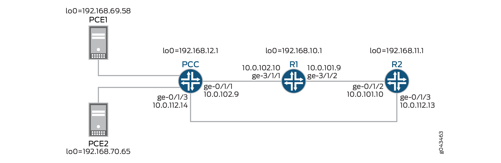
In this example, PCC is the ingress router that connects to two external stateful PCEs: PCE1 and PCE2.
When there is a new demand, the active stateful PCE dynamically initiates an LSP to meet the requirement. Since PCC is configured with the capability of supporting the PCE-initiated LSP, path computation on PCC is performed as follows:
A PCE sends a PCCreate message to the PCC to initiate and provision an LSP. The PCC sets up the PCE-initiated LSP using the parameters received from the PCE, and automatically delegates the PCE-initiated LSP to the PCE that initiated it.
In this example, PCE1 is the active stateful PCE that initiates and provisions the PCE-initiated LSP on PCC. On receiving the PCE-initiated LSP parameters, PCC sets up the LSP and automatically delegates the PCE-initiated LSP to PCE1.
When the PCEP session between PCC and PCE1 is terminated, PCC starts two timers for the PCE1-initiated LSP: delgation cleanup timeout and the LSP cleanup timer. During this time, PCE1 or PCE2 can acquire control of the PCE-initiated LSP.
If PCE2 acquires control over the PCE-initiated LSP before the expiration of the LSP cleanup timer, PCC delegates the PCE-initiated LSP to PCE2, and the LSP cleanup timer and the delegation cleanup timeout are stopped.
If the delegation cleanup timeout expired, and neither PCE1 nor PCE2 acquired control over the PCE-initiated LSP, PCC takes local control of the non-delegated PCE-initiated LSP until the expiration of the LSP cleanup timer.
After the expiration of the LSP cleanup timer, PCC deletes the PCE-initiated LSP provisioned by PCE1.
Configuration
CLI Quick Configuration
To quickly configure this example, copy the
following commands, paste them into a text file, remove any line breaks,
change any details necessary to match your network configuration,
and then copy and paste the commands into the CLI at the [edit] hierarchy level.
PCC
set interfaces ge-0/1/1 unit 0 family inet address 10.0.102.9/24 set interfaces ge-0/1/1 unit 0 family iso set interfaces ge-0/1/1 unit 0 family mpls set interfaces ge-0/1/3 unit 0 family inet address 10.0.112.14/24 set interfaces ge-0/1/3 unit 0 family iso set interfaces ge-0/1/3 unit 0 family mpls set interfaces lo0 unit 0 family inet address 192.168.12.1/32 set protocols rsvp interface all set protocols rsvp interface fxp0.0 disable set protocols mpls lsp-external-controller ppcd set protocols mpls interface all set protocols mpls interface fxp0.0 disable set protocols ospf traffic-engineering set protocols ospf area 0.0.0.0 interface all set protocols ospf area 0.0.0.0 interface fxp0.0 disable set protocols pcep pce-group PCEGROUP pce-type active set protocols pcep pce-group PCEGROUP pce-type stateful set protocols pcep pce-group PCEGROUP lsp-provisioning set protocols pcep pce-group PCEGROUP lsp-cleanup-timer 30 set protocols pcep pce PCE1 destination-ipv4-address 192.168.69.58 set protocols pcep pce PCE1 destination-port 4189 set protocols pcep pce PCE1 pce-group PCEGROUP set protocols pcep pce PCE2 destination-ipv4-address 192.168.70.65 set protocols pcep pce PCE2 destination-port 4189 set protocols pcep pce PCE2 pce-group PCEGROUP
R1
set interfaces ge-3/1/1 unit 0 family inet address 10.0.102.10/24 set interfaces ge-3/1/1 unit 0 family iso set interfaces ge-3/1/1 unit 0 family mpls set interfaces ge-3/1/2 unit 0 family inet address 10.0.101.9/24 set interfaces ge-3/1/2 unit 0 family iso set interfaces ge-3/1/2 unit 0 family mpls set interfaces lo0 unit 0 family inet address 192.168.10.1/32 set protocols rsvp interface all set protocols rsvp interface fxp0.0 disable set protocols mpls interface all set protocols mpls interface fxp0.0 disable set protocols ospf traffic-engineering set protocols ospf area 0.0.0.0 interface all set protocols ospf area 0.0.0.0 interface fxp0.0 disable
R2
set interfaces ge-0/1/1 unit 0 family inet address 10.0.101.10/24 set interfaces ge-0/1/1 unit 0 family iso set interfaces ge-0/1/1 unit 0 family mpls set interfaces ge-0/1/3 unit 0 family inet address 10.0.112.13/24 set interfaces ge-0/1/3 unit 0 family iso set interfaces ge-0/1/3 unit 0 family mpls set interfaces lo0 unit 0 family inet address 192.168.11.1/32 set protocols rsvp interface all set protocols rsvp interface fxp0.0 disable set protocols mpls interface all set protocols mpls interface fxp0.0 disable set protocols ospf traffic-engineering set protocols ospf area 0.0.0.0 interface all set protocols ospf area 0.0.0.0 interface fxp0.0 disable
Procedure
Step-by-Step Procedure
The following example requires you to navigate various levels in the configuration hierarchy. For information about navigating the CLI, see Using the CLI Editor in Configuration Mode.
To configure the PCC router:
Repeat this procedure for every Juniper Networks ingress router in the MPLS domain, after modifying the appropriate interface names, addresses, and any other parameters for each router.
Configure the interfaces.
To enable MPLS, include the protocol family on the interface so that the interface does not discard incoming MPLS traffic.
[edit interfaces]user@PCC# set ge-0/1/1 unit 0 family inet address 10.0.102.9/24 user@PCC# set ge-0/1/1 unit 0 family iso user@PCC# set ge-0/1/1 unit 0 family mpls user@PCC# set ge-0/1/3 unit 0 family inet address 10.0.112.14/24 user@PCC# set ge-0/1/3 unit 0 family iso user@PCC# set ge-0/1/3 unit 0 family mpls user@PCC# set lo0 unit 0 family inet address 192.168.12.1/32Enable RSVP on all interfaces of the PCC, excluding the management interface.
[edit protocols]user@PCC# set rsvp interface all user@PCC# set rsvp interface fxp0.0 disableEnable external control of LSPs by the PCEs.
[edit protocols] user@PCC# set mpls lsp-external-controller pccd
Enable MPLS on all interfaces of the PCC, excluding the management interface.
[edit protocols] user@PCC# set mpls interface all user@PCC# set mpls interface fxp0.0 disable
Configure OSPF on all interfaces of the PCC, excluding the management interface.
[edit protocols] user@PCC# set ospf traffic-engineering user@PCC# set ospf area 0.0.0.0 interface all user@PCC# set ospf area 0.0.0.0 interface fxp0.0 disable user@PCC# set ospf interface lo0.0
Define the PCE group and enable support of PCE-initiated LSPs for the PCE group.
[edit protocols] user@PCC# set protocols pcep pce-group PCEGROUP pce-type active user@PCC# set protocols pcep pce-group PCEGROUP pce-type stateful user@PCC# set protocols pcep pce-group PCEGROUP lsp-provisioning user@PCC# set protocols pcep pce-group PCEGROUP lsp-cleanup-timer 30
Define the PCEs that connect to the PCC.
[edit protocols] user@PCC# set pcep pce PCE1 destination-ipv4-address 192.168.69.58 user@PCC# set pcep pce PCE1 destination-port 4189 user@PCC# set pcep pce PCE1 pce-group PCEGROUP user@PCC# set pcep pce PCE2 destination-ipv4-address 192.168.70.65 user@PCC# set pcep pce PCE2 destination-port 4189 user@PCC# set pcep pce PCE2 pce-group PCEGROUP
Results
From configuration mode, confirm your configuration
by entering the show interfaces and show protocols commands. If the output does not display the intended configuration,
repeat the instructions in this example to correct the configuration.
user@PCC# show interfaces
ge-0/1/1 {
unit 0 {
family inet {
address 10.0.102.9/24;
}
family iso;
family mpls;
}
}
ge-0/1/3 {
unit 0 {
family inet {
address 10.0.112.14/24;
}
family iso;
family mpls;
}
}
lo0 {
unit 0 {
family inet {
address 192.168.12.1/32;
}
}
}
user@PCC# show protocols
rsvp {
interface all;
}
interface fxp0.0 {
disable;
}
}
mpls {
lsp-external-controller pccd;
interface all;
interface fxp0.0 {
disable;
}
}
ospf {
traffic-engineering;
area 0.0.0.0 {
interface all;
interface fxp0.0 {
disable;
}
}
}
pce-group PCEGROUP {
pce-type active stateful;
lsp-provisioning;
lsp-cleanup-timer 30;
}
pce PCE1 {
destination-ipv4-address 192.168.69.58;
destination-port 4189;
pce-group PCEGROUP;
}
pce PCE2 {
destination-ipv4-address 192.168.70.65;
destination-port 4189;
pce-group PCEGROUP;
}
If you are done configuring the device, enter commit from configuration mode.
Verification
Confirm that the configuration is working properly.
- Verifying PCC Status
- Verifying PCE1 Status
- Verifying the PCE-Initiated LSP Status When the LSP Is Externally Provisioned
Verifying PCC Status
Purpose
Verify the PCEP session status and LSP summary between the PCC and the connected PCEs.
Action
From operational mode, run the show path-computation-client
status command.
user@PCC# show path-computation-client status Session Type Provisioning Status PCE1 Stateful Active On Up PCE2 Stateful Active On Up LSP Summary Total number of LSPs : 1 Static LSPs : 0 Externally controlled LSPs : 0 Externally provisioned LSPs : 1/16000 (current/limit) Orphaned LSPs : 0 PCE1 (main) Delegated : 1 Externally provisioned : 1 PCE2 Delegated : 0 Externally provisioned : 0
Meaning
The output displays the status of the PCEP session between the active stateful PCEs and the PCC. It also displays information about the different types of LSPs on the PCC, and the number of LSPs provisioned by the connected PCEs and delegated to them.
PCE1 is the main active PCE and has one PCE-initiated LSP that has been automatically delegated to it by the PCC.
Verifying PCE1 Status
Purpose
Verify the status of the main active stateful PCE.
Action
From operational mode, run the show path-computation-client
active-pce detail command.
user@PCC# show path-computation-client active-pce PCE PCE1 -------------------------------------------- General IP address : 192.168.69.58 Priority : 0 PCE status : PCE_STATE_UP Session type : PCE_TYPE_STATEFULACTIVE LSP provisioning allowed : On LSP cleanup timer : 30 [s] PCE-mastership : main Max unknown messages : 5 Keepalives received : 0 Keepalives sent : 0 Dead timer : 0 [s] Elapsed as main current : 1 [s] Elapsed as main total : 446380 [s] Unknown msgs/min rate : 0 Session failures : 2198 Corrupted messages : 0 Delegation timeout set : 30 Delegation timeout in : 0 [s] Delegation failures : 0 Connection down : 167092 [s] Counters PCReqs Total: 0 last 5min: 0 last hour: 0 PCReps Total: 0 last 5min: 0 last hour: 0 PCRpts Total: 5 last 5min: 5 last hour: 5 PCUpdates Total: 0 last 5min: 0 last hour: 0 PCCreates Total: 1 last 5min: 1 last hour: 1 Timers Local Keepalive timer: 30 [s] Dead timer: 120 [s] LSP cleanup timer: 30 [s] Remote Keepalive timer: 0 [s] Dead timer: 0 [s] LSP cleanup timer: - [s] Errors PCErr-recv PCErr-sent PCE-PCC-NTFS PCC-PCE-NTFS
Meaning
The output displays information about the current active
stateful PCE to which the PCC is connected. The PCE status output field indicates the current status of the PCEP session between
a PCE and PCC.
For PCE1, the status of the PCEP session is PCE_STATE_UP, which indicates that the PCEP session has been established with
the PCC.
Verifying the PCE-Initiated LSP Status When the LSP Is Externally Provisioned
Purpose
Verify the status of the PCE-initiated LSP.
Action
From operational mode, run the show mpls lsp externally-provisioned
detail command.
user@PCC# show mpls lsp externally-provisioned detail Ingress LSP: 1 sessions 10.0.101.10 From: 10.0.102.9, State: Up, ActiveRoute: 0, LSPname: lsp15 ActivePath: path1 (primary) Link protection desired LSPtype: Externally Provisioned, Penultimate hop popping LSP Control Status: Externally controlled LoadBalance: Random Encoding type: Packet, Switching type: Packet, GPID: IPv4 *Primary path1 State: Up Priorities: 7 0 Bandwidth: 8Mbps Computed ERO (S [L] denotes strict [loose] hops): (CSPF metric: 3) 10.0.102.10 S 10.0.101.9 S Received RRO (ProtectionFlag 1=Available 2=InUse 4=B/W 8=Node 10=SoftPreempt 20=Node-ID): 10.0.102.10 S 10.0.101.9 S
Meaning
In the output, the LSPtype output field
shows that the LSP is externally provisioned.
The PCEP session between PCC and PCE1 is up, and the PCC receives the following PCE-initiated LSP parameters:
ERO (path)—10.0.102.10 and 10.0.101.9
Bandwidth—8 Mbps
Priority—7 0 (setup and hold values)
Configuring Path Computation Element Protocol for MPLS RSVP-TE with Support of PCE-Initiated Point-to-Point LSPs
You can configure a Path Computation Client (PCC) with the capability of supporting dynamically created label switched paths (LSPs) from a centralized external path computing entity. A stateful Path Computaiton Element (PCE) can be used to perform external path computation and generate dynamic LSPs when there is an increase in demand.
A PCC creates the PCE-initiated point-to-point LSP using the PCE-provided LSP parameters, or parameters from a pre-configured LSP template when the PCE does not provision the LSP, and automatically delegates the PCE-initiated point-to-point LSP to the respective PCE. As a result, for PCE-initiated LSPs, there is no need for a locally configured LSP on the PCC.
A CLI-controlled LSP, PCE-controlled LSP, and PCE-initiated LSP can coexist with each other on a PCC.
Before you begin:
Configure the device interfaces.
Configure MPLS and RSVP-TE.
Configure OSPF or any other IGP protocol.
To configure PCC to support PCE-initiated point-to-point LSPs, complete the following tasks:
Sample Output
[edit]
user@PCC# edit protocols pcep
[edit protocols pcep]
user@PCC# set message-rate-limit 50
[edit protocols pcep]
user@PCC# set max-provisioned-lsps 16000
[edit protocols pcep]
user@PCC# edit pce PCE
[edit protocols pcep pce PCE]
user@PCC# set delegation-cleanup-timeout 20
[edit protocols pcep pce PCE]
user@PCC# set destination-ipv4-address 192.168.69.58
[edit protocols pcep pce PCE]
user@PCC# set destination-port 4189
[edit protocols pcep pce PCE]
user@PCC# set lsp-cleanup-timer 50
[edit protocols pcep pce PCE]
user@PCC# set lsp-provisioning
[edit protocols pcep pce PCE]
user@PCC# set max-unknown-messages 5
[edit protocols pcep pce PCE]
user@PCC# set max-unknown-requests 5
[edit protocols pcep pce PCE]
user@PCC# set request-timer 50
[edit protocols pcep pce PCE]
user@PCC# up
[edit protocols pcep]
user@PCC# show
message-rate-limit 50;
max-provisioned-lsps 16000;
pce PCE {
destination-ipv4-address 192.168.69.58;
destination-port 4189;
lsp-provisioning;
lsp-cleanup-timer 50;
request-timer 50;
max-unknown-requests 5;
max-unknown-messages 5;
delegation-cleanup-timeout 20;
}
[edit protocols pcep]
user@PCC# commit
commit completeExample: Configuring Path Computation Element Protocol for MPLS RSVP-TE with Support for PCE-Controlled Point-to-Multipoint LSPs
This example shows how to configure the Path Computation Client (PCC) with the capability of reporting point-to-multipoint traffic engineered label-switched paths (TE LSPs) to a Path Computation Element (PCE).
Requirements
This example uses the following hardware and software components:
Three routers that can be a combination of ACX Series, M Series, MX Series, or T Series routers.
One virtual machine configured with Virtual Route Reflector (VRR) feature.
A TCP connection to an external stateful PCE from the VRR.
Junos OS Release 16.1 or later running on the PCC.
Before you begin:
Configure the device interfaces.
Configure MPLS and RSVP-TE.
Configure OSPF or any other IGP protocol.
Overview
After a PCEP session is established between a PCE and a PCC, the PCC reports all the LSPs in the system to the PCE for LSP state synchronization. This includes PCC-controlled, PCE-delegated, and PCE-initiated point-to-point LSPs. Starting with Junos OS Release 15.1F6 and 16.1R1, this capability is extended to report point-to-multipoint LSPs as well.
By default, PCE control of point-to-multipoint LSPs is not supported
on a PCC. To add this capability, include the p2mp-lsp-report-capability statement at the [edit protocols pcep pce pce-name] or [edit protocols pcep pce-group group-id] hierarchy levels.
Topology
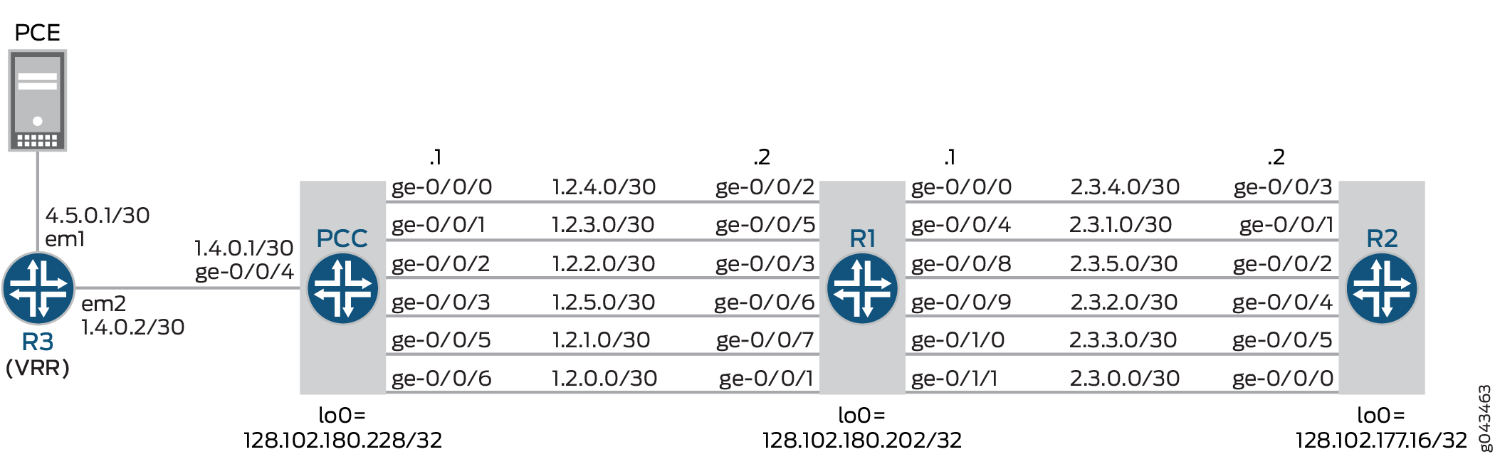
In this example, PCC is the ingress router, Router R1 is the transit router, and Router R2 is the egress router. PCC is connected to a Virtual Route Reflector (VRR) that is connected to a PCE. There are many point-to-multipoint interfaces between PCC, Router R1, and Router R2.
The reporting of point-to-multipoint LSPs is executed as follows:
If Router PCC is configured with point-to-point and point-to-multipoint LSPs without the support for point-to-multipoint reporting capability, only the point-to-point LSPs are reported to the connected PCE. By default, a PCC does not support point-to-multipoint LSP reporting capability.
When Router PCC is configured with point-to-multipoint LSP reporting capability, PCC first advertises this capability to PCE through a report message.
By default, a PCE provides support for point-to-multipoint LSP capability. On receiving the PCC’s advertisement for point-to-multipoint LSP capability, the PCE in return advertises its capability to the PCC.
On receiving the PCE’s advertisement of the point-to-multipoint capability, PCC reports all branches of point-to-multipoint LSPs to the PCE using the update message.
Once all the LSPs are reported to the PCE, LSP state is synchronized between the PCE and PCC.
Configuration
CLI Quick Configuration
To quickly configure this example, copy the
following commands, paste them into a text file, remove any line breaks,
change any details necessary to match your network configuration,
and then copy and paste the commands into the CLI at the [edit] hierarchy level.
PCC
set interfaces ge-0/0/0 unit 0 family inet address 1.2.4.1/30 set interfaces ge-0/0/0 unit 0 family mpls set interfaces ge-0/0/1 unit 0 family inet address 1.2.3.1/30 set interfaces ge-0/0/1 unit 0 family mpls set interfaces ge-0/0/2 unit 0 family inet address 1.2.2.1/30 set interfaces ge-0/0/2 unit 0 family mpls set interfaces ge-0/0/3 unit 0 family inet address 1.2.5.1/30 set interfaces ge-0/0/3 unit 0 family mpls set interfaces ge-0/0/4 unit 0 family inet address 1.4.0.1/30 set interfaces ge-0/0/4 unit 0 family mpls set interfaces ge-0/0/5 unit 0 family inet address 1.2.1.1/30 set interfaces ge-0/0/5 unit 0 family mpls set interfaces ge-0/0/6 unit 0 family inet address 1.2.0.1/30 set interfaces ge-0/0/6 unit 0 family mpls set routing-options autonomous-system 100 set protocols rsvp interface all set protocols rsvp interface fxp0.0 disable set protocols mpls lsp-external-controller pccd pce-controlled-lsp pcc_delegated_no_cspf_* label-switched-path-template lsp_template_no_cspf set protocols mpls lsp-external-controller pccd pce-controlled-lsp pce_initiated_no_ero_no_cspf_* label-switched-path-template lsp_template_no_cspf set protocols mpls lsp-external-controller pccd pce-controlled-lsp pce_initiated_loose_ero_no_cspf_* label-switched-path-template lsp_template_no_cspf set protocols mpls traffic-engineering database import policy TE set protocols mpls admin-groups violet 1 set protocols mpls admin-groups indigo 2 set protocols mpls admin-groups blue 3 set protocols mpls admin-groups green 4 set protocols mpls admin-groups yellow 5 set protocols mpls admin-groups orange 6 set protocols mpls label-switched-path lsp_template_no_cspf template set protocols mpls label-switched-path lsp_template_no_cspf no-cspf set protocols mpls label-switched-path lsp1-pcc to 128.102.177.16 set protocols mpls label-switched-path lsp2-pcc to 128.102.177.16 set protocols mpls label-switched-path lsp2-pcc lsp-external-controller pccd set protocols mpls path loose-path 1.2.3.2 loose set protocols mpls path strict-path 1.2.3.2 strict set protocols mpls path strict-path 2.3.3.2 strict set protocols mpls path path-B set protocols mpls path path-C set protocols mpls interface all set protocols mpls interface ge-0/0/6.0 admin-group violet set protocols mpls interface ge-0/0/5.0 admin-group indigo set protocols mpls interface ge-0/0/2.0 admin-group blue set protocols mpls interface ge-0/0/1.0 admin-group green set protocols mpls interface ge-0/0/0.0 admin-group yellow set protocols mpls interface ge-0/0/3.0 admin-group orange set protocols mpls interface fxp0.0 disable set protocols bgp group northstar type internal set protocols bgp group northstar local-address 128.102.180.228 set protocols bgp group northstar family traffic-engineering unicast set protocols bgp group northstar export TE set protocols bgp group northstar neighbor 128.102.180.215 set protocols ospf traffic-engineering set protocols ospf area 0.0.0.0 interface lo0.0 set protocols ospf area 0.0.0.0 interface ge-0/0/6.0 set protocols ospf area 0.0.0.0 interface ge-0/0/5.0 set protocols ospf area 0.0.0.0 interface ge-0/0/2.0 set protocols ospf area 0.0.0.0 interface ge-0/0/1.0 set protocols ospf area 0.0.0.0 interface ge-0/0/0.0 set protocols ospf area 0.0.0.0 interface ge-0/0/3.0 set protocols ospf area 0.0.0.0 interface ge-0/0/4.0 interface-type p2p set protocols pcep pce pce1 local-address 10.102.180.228 set protocols pcep pce pce1 destination-ipv4-address 10.102.180.246 set protocols pcep pce pce1 destination-port 4189 set protocols pcep pce pce1 pce-type active set protocols pcep pce pce1 pce-type stateful set protocols pcep pce pce1 lsp-provisioning set protocols pcep pce pce1 lsp-cleanup-timer 0 set protocols pcep pce pce1 delegation-cleanup-timeout 60 set protocols pcep pce pce1 p2mp-lsp-report-capability set policy-options policy-statement TE term 1 from family traffic-engineering set policy-options policy-statement TE term 1 then accept
R1
set interfaces ge-0/0/0 unit 0 family inet address 2.3.4.1/30 set interfaces ge-0/0/0 unit 0 family mpls set interfaces ge-0/0/1 unit 0 family inet address 1.2.0.2/30 set interfaces ge-0/0/1 unit 0 family mpls set interfaces ge-0/0/2 unit 0 family inet address 1.2.4.2/30 set interfaces ge-0/0/2 unit 0 family mpls set interfaces ge-0/0/3 unit 0 family inet address 1.2.2.2/30 set interfaces ge-0/0/3 unit 0 family mpls set interfaces ge-0/0/4 unit 0 family inet address 2.3.1.1/30 set interfaces ge-0/0/4 unit 0 family mpls set interfaces ge-0/0/5 unit 0 family inet address 1.2.3.2/30 set interfaces ge-0/0/5 unit 0 family mpls set interfaces ge-0/0/6 unit 0 family inet address 1.2.5.2/30 set interfaces ge-0/0/6 unit 0 family mpls set interfaces ge-0/0/7 unit 0 family inet address 1.2.1.2/30 set interfaces ge-0/0/7 unit 0 family mpls set interfaces ge-0/0/8 unit 0 family inet address 2.3.5.1/30 set interfaces ge-0/0/8 unit 0 family mpls set interfaces ge-0/0/9 unit 0 family inet address 2.3.2.1/30 set interfaces ge-0/0/9 unit 0 family mpls set interfaces ge-0/1/0 unit 0 family inet address 2.3.3.1/30 set interfaces ge-0/1/0 unit 0 family mpls set interfaces ge-0/1/1 unit 0 family inet address 2.3.0.1/30 set interfaces ge-0/1/1 unit 0 family mpls set protocols rsvp interface all set protocols rsvp interface fxp0.0 disable set protocols mpls admin-groups violet 1 set protocols mpls admin-groups indigo 2 set protocols mpls admin-groups blue 3 set protocols mpls admin-groups green 4 set protocols mpls admin-groups yellow 5 set protocols mpls admin-groups orange 6 set protocols mpls interface all set protocols mpls interface fxp0.0 disable set protocols mpls interface ge-0/0/1.0 admin-group violet set protocols mpls interface ge-0/0/7.0 admin-group indigo set protocols mpls interface ge-0/0/3.0 admin-group blue set protocols mpls interface ge-0/0/5.0 admin-group green set protocols mpls interface ge-0/0/2.0 admin-group yellow set protocols mpls interface ge-0/0/6.0 admin-group orange set protocols mpls interface ge-0/1/1.0 admin-group violet set protocols mpls interface ge-0/0/4.0 admin-group indigo set protocols mpls interface ge-0/0/9.0 admin-group blue set protocols mpls interface ge-0/1/0.0 admin-group green set protocols mpls interface ge-0/0/0.0 admin-group yellow set protocols mpls interface ge-0/0/8.0 admin-group orange set protocols ospf traffic-engineering set protocols ospf area 0.0.0.0 interface lo0.0 set protocols ospf area 0.0.0.0 interface ge-0/0/1.0 set protocols ospf area 0.0.0.0 interface ge-0/0/7.0 set protocols ospf area 0.0.0.0 interface ge-0/0/3.0 set protocols ospf area 0.0.0.0 interface ge-0/0/5.0 set protocols ospf area 0.0.0.0 interface ge-0/0/2.0 set protocols ospf area 0.0.0.0 interface ge-0/0/6.0 set protocols ospf area 0.0.0.0 interface ge-0/1/1.0
R2
set interfaces ge-0/0/0 unit 0 family inet address 2.3.0.2/30 set interfaces ge-0/0/0 unit 0 family mpls set interfaces ge-0/0/1 unit 0 family inet address 2.3.1.2/30 set interfaces ge-0/0/1 unit 0 family mpls set interfaces ge-0/0/2 unit 0 family inet address 2.3.5.2/30 set interfaces ge-0/0/2 unit 0 family mpls set interfaces ge-0/0/3 unit 0 family inet address 2.3.4.2/30 set interfaces ge-0/0/3 unit 0 family mpls set interfaces ge-0/0/4 unit 0 family inet address 2.3.2.2/30 set interfaces ge-0/0/4 unit 0 family mpls set interfaces ge-0/0/5 unit 0 family inet address 2.3.3.2/30 set interfaces ge-0/0/5 unit 0 family mpls set protocols rsvp interface all set protocols rsvp interface fxp0.0 disable set protocols mpls admin-groups violet 1 set protocols mpls admin-groups indigo 2 set protocols mpls admin-groups blue 3 set protocols mpls admin-groups green 4 set protocols mpls admin-groups yellow 5 set protocols mpls admin-groups orange 6 set protocols mpls interface all set protocols mpls interface fxp0.0 disable set protocols mpls interface ge-0/0/0.0 admin-group violet set protocols mpls interface ge-0/0/1.0 admin-group indigo set protocols mpls interface ge-0/0/4.0 admin-group blue set protocols mpls interface ge-0/0/5.0 admin-group green set protocols mpls interface ge-0/0/3.0 admin-group yellow set protocols mpls interface ge-0/0/2.0 admin-group orange set protocols ospf traffic-engineering set protocols ospf area 0.0.0.0 interface ge-0/0/0.0 set protocols ospf area 0.0.0.0 interface ge-0/0/1.0 set protocols ospf area 0.0.0.0 interface ge-0/0/4.0 set protocols ospf area 0.0.0.0 interface ge-0/0/5.0 set protocols ospf area 0.0.0.0 interface ge-0/0/3.0 set protocols ospf area 0.0.0.0 interface ge-0/0/2.0 set protocols ospf area 0.0.0.0 interface lo0.0 passive
R3
set interfaces em0 unit 0 family inet address 10.102.180.215/19 set interfaces em1 unit 0 family inet address 4.5.0.1/30 set interfaces em2 unit 0 family inet address 1.4.0.2/30 set interfaces em2 unit 0 family mpls set routing-options router-id 128.102.180.215 set routing-options autonomous-system 100 set protocols topology-export set protocols rsvp interface all set protocols mpls lsp-external-controller pccd set protocols mpls traffic-engineering database import igp-topology set protocols mpls traffic-engineering database import policy TE set protocols mpls interface all set protocols bgp group northstar type internal set protocols bgp group northstar local-address 128.102.180.215 set protocols bgp group northstar family traffic-engineering unicast set protocols bgp group northstar neighbor 128.102.180.228 set protocols ospf area 0.0.0.0 interface lo0.0 set protocols ospf area 0.0.0.0 interface em2.0 interface-type p2p set policy-options policy-statement TE from family traffic-engineering set policy-options policy-statement TE then accept
Procedure
Step-by-Step Procedure
The following example requires you to navigate various levels in the configuration hierarchy. For information about navigating the CLI, see Using the CLI Editor in Configuration Mode.
To configure the PCC router:
Configure the interfaces of Router PCC. To enable MPLS, include the protocol family on the interface so that the interface does not discard incoming MPLS traffic.
[edit interfaces] user@PCC# set ge-0/0/0 unit 0 family inet address 1.2.4.1/30 user@PCC# set ge-0/0/0 unit 0 family mpls user@PCC# set ge-0/0/1 unit 0 family inet address 1.2.3.1/30 user@PCC# set ge-0/0/1 unit 0 family mpls user@PCC# set ge-0/0/2 unit 0 family inet address 1.2.2.1/30 user@PCC# set ge-0/0/2 unit 0 family mpls user@PCC# set ge-0/0/3 unit 0 family inet address 1.2.5.1/30 user@PCC# set ge-0/0/3 unit 0 family mpls user@PCC# set ge-0/0/4 unit 0 family inet address 1.4.0.1/30 user@PCC# set ge-0/0/4 unit 0 family mpls user@PCC# set ge-0/0/5 unit 0 family inet address 1.2.1.1/30 user@PCC# set ge-0/0/5 unit 0 family mpls user@PCC# set ge-0/0/6 unit 0 family inet address 1.2.0.1/30 user@PCC# set ge-0/0/6 unit 0 family mpls
Configure the autonomous system number for Router PCC.
[edit routing-options] user@PCC# set autonomous-system 100
Enable RSVP on all interfaces of Router PCC, excluding the management interface.
[edit protocols]
user@PCC# set rsvp interface all
user@PCC# set rsvp interface fxp0.0 disable
Enable MPLS on all the interfaces of Router PCC, excluding the management interface.
[edit protocols]
user@PCC# set mpls interface all
user@PCC# set mpls interface fxp0.0 disable
Configure a dynamic LSP and disable automatic path computation for the LSP.
[edit protocols] user@PCC# set mpls label-switched-path lsp_template_no_cspf template user@PCC# set mpls label-switched-path lsp_template_no_cspf no-cspf
Configure point-to-multipoint LSPs and define external path computing entity for the LSP.
[edit protocols] user@PCC# set mpls label-switched-path lsp1-pcc to 128.102.177.16 user@PCC# set mpls label-switched-path lsp2-pcc to 128.102.177.16 user@PCC# set mpls label-switched-path lsp2-pcc lsp-external-controller pccd
Enable external path computing for the MPLS LSPs and assign a template for externally provisioned LSPs.
[edit protocols] user@PCC# set mpls lsp-external-controller pccd pce-controlled-lsp pcc_delegated_no_cspf_* label-switched-path-template lsp_template_no_cspf user@PCC# set mpls lsp-external-controller pccd pce-controlled-lsp pce_initiated_no_ero_no_cspf_* label-switched-path-template lsp_template_no_cspf user@PCC# set mpls lsp-external-controller pccd pce-controlled-lsp pce_initiated_loose_ero_no_cspf_* label-switched-path-template lsp_template_no_cspf
Configure the LSPs that have local control and are overridden by the PCE-provided LSP parameters.
[edit protocols] user@PCC# set mpls path loose-path 1.2.3.2 loose user@PCC# set mpls path strict-path 1.2.3.2 strict user@PCC# set mpls path strict-path 2.3.3.2 strict user@PCC# set mpls path path-B user@PCC# set mpls path path-C
Configure MPLS administrative group policies for constrained-path LSP computation.
[edit protocols] user@PCC# set mpls admin-groups violet 1 user@PCC# set mpls admin-groups indigo 2 user@PCC# set mpls admin-groups blue 3 user@PCC# set mpls admin-groups green 4 user@PCC# set mpls admin-groups yellow 5 user@PCC# set mpls admin-groups orange 6
Assign the configured administrative group policies to Router PCC interfaces.
[edit protocols] user@PCC# set mpls interface ge-0/0/6.0 admin-group violet user@PCC# set mpls interface ge-0/0/5.0 admin-group indigo user@PCC# set mpls interface ge-0/0/2.0 admin-group blue user@PCC# set mpls interface ge-0/0/1.0 admin-group green user@PCC# set mpls interface ge-0/0/0.0 admin-group yellow user@PCC# set mpls interface ge-0/0/3.0 admin-group orange
Configure a traffic engineering database (TED) import policy.
[edit protocols] user@PCC# set mpls traffic-engineering database import policy TE
Configure a BGP internal group.
[edit protocols] user@PCC# set bgp group northstar type internal user@PCC# set bgp group northstar local-address 128.102.180.228 user@PCC# set bgp group northstar neighbor 128.102.180.215
Configure traffic engineering for BGP and assign the export policy.
[edit protocols] user@PCC# set bgp group northstar family traffic-engineering unicast user@PCC# set bgp group northstar export TE
Configure OSPF area 0 on all the point-to-multipoint interfaces of Router PCC.
[edit protocols] user@PCC# set ospf area 0.0.0.0 interface lo0.0 user@PCC# set ospf area 0.0.0.0 interface ge-0/0/6.0 user@PCC# set ospf area 0.0.0.0 interface ge-0/0/5.0 user@PCC# set ospf area 0.0.0.0 interface ge-0/0/2.0 user@PCC# set ospf area 0.0.0.0 interface ge-0/0/1.0 user@PCC# set ospf area 0.0.0.0 interface ge-0/0/0.0 user@PCC# set ospf area 0.0.0.0 interface ge-0/0/3.0
Configure OSPF area 0 on the point-to-point interface of Router PCC.
[edit protocols] user@PCC# set ospf area 0.0.0.0 interface ge-0/0/4.0 interface-type p2p
Enable traffic engineering for OSPF.
[edit protocols] user@PCC# set ospf traffic-engineering
Define the PCE that Router PCC connects to, and configure the the PCE parameters.
[edit protocols] user@PCC# set pcep pce pce1 local-address 10.102.180.228 user@PCC# set pcep pce pce1 destination-ipv4-address 10.102.180.246 user@PCC# set pcep pce pce1 destination-port 4189 user@PCC# set pcep pce pce1 pce-type active user@PCC# set pcep pce pce1 pce-type stateful user@PCC# set pcep pce pce1 lsp-provisioning user@PCC# set pcep pce pce1 lsp-cleanup-timer 0 user@PCC# set pcep pce pce1 delegation-cleanup-timeout 60
Configure Router PCC to enable point-to-multipoint LSP capability for external path computing.
[edit protocols] set pcep pce pce1 p2mp-lsp-report-capability
Configure the traffic engineering policy.
[edit policy-options] user@PCC# set policy-statement TE term 1 from family traffic-engineering user@PCC# set policy-statement TE term 1 then accept
Results
From configuration mode, confirm your configuration
by entering the show interfaces and show protocols commands. If the output does not display the intended configuration,
repeat the instructions in this example to correct the configuration.
user@PCC# show interfaces
ge-0/0/0 {
unit 0 {
family inet {
address 1.2.4.1/30;
}
family mpls;
}
}
ge-0/0/1 {
unit 0 {
family inet {
address 1.2.3.1/30;
}
family mpls;
}
}
ge-0/0/2 {
unit 0 {
family inet {
address 1.2.2.1/30;
}
family mpls;
}
}
ge-0/0/3 {
unit 0 {
family inet {
address 1.2.5.1/30;
}
family mpls;
}
}
ge-0/0/4 {
unit 0 {
family inet {
address 1.4.0.1/30;
}
family mpls;
}
}
ge-0/0/5 {
unit 0 {
family inet {
address 1.2.1.1/30;
}
family mpls;
}
}
ge-0/0/6 {
unit 0 {
family inet {
address 1.2.0.1/30;
}
family mpls;
}
}
user@PCC# show protocols
rsvp {
interface all;
interface fxp0.0 {
disable;
}
}
mpls {
lsp-external-controller pccd {
pce-controlled-lsp pcc_delegated_no_cspf_* {
label-switched-path-template {
lsp_template_no_cspf;
}
}
pce-controlled-lsp pce_initiated_no_ero_no_cspf_* {
label-switched-path-template {
lsp_template_no_cspf;
}
}
pce-controlled-lsp pce_initiated_loose_ero_no_cspf_* {
label-switched-path-template {
lsp_template_no_cspf;
}
}
}
traffic-engineering {
database {
import {
policy TE;
}
}
}
admin-groups {
violet 1;
indigo 2;
blue 3;
green 4;
yellow 5;
orange 6;
}
label-switched-path lsp_template_no_cspf {
template;
no-cspf;
}
label-switched-path lsp1-pcc {
to 128.102.177.16;
}
label-switched-path lsp2-pcc {
to 128.102.177.16;
lsp-external-controller pccd;
}
path loose-path {
1.2.3.2 loose;
}
path strict-path {
1.2.3.2 strict;
2.3.3.2 strict;
}
path path-B;
path path-C;
interface all;
interface ge-0/0/6.0 {
admin-group violet;
}
interface ge-0/0/5.0 {
admin-group indigo;
}
interface ge-0/0/2.0 {
admin-group blue;
}
interface ge-0/0/1.0 {
admin-group green;
}
interface ge-0/0/0.0 {
admin-group yellow;
}
interface ge-0/0/3.0 {
admin-group orange;
}
interface fxp0.0 {
disable;
}
}
bgp {
group northstar {
type internal;
local-address 128.102.180.228;
family traffic-engineering {
unicast;
}
export TE;
neighbor 128.102.180.215;
}
}
ospf {
traffic-engineering;
area 0.0.0.0 {
interface lo0.0;
interface ge-0/0/6.0;
interface ge-0/0/5.0;
interface ge-0/0/2.0;
interface ge-0/0/1.0;
interface ge-0/0/0.0;
interface ge-0/0/3.0;
interface ge-0/0/4.0 {
interface-type p2p;
}
}
}
pcep {
pce pce1 {
local-address 10.102.180.228;
destination-ipv4-address 10.102.180.246;
destination-port 4189;
pce-type active stateful;
lsp-provisioning;
lsp-cleanup-timer 0;
delegation-cleanup-timeout 60;
p2mp-lsp-report-capability;
}
}
Verification
Confirm that the configuration is working properly.
Verifying LSP Configuration on the PCC
Purpose
Verify the LSP type and running state of the point-to-multipoint LSP.
Action
From operational mode, run the show mpls lsp extensive command.
user@PCC> show mpls lsp extensive
Ingress LSP: 2 sessions
128.102.177.16
From: 128.102.180.228, State: Up, ActiveRoute: 0, LSPname: lsp1-pcc
ActivePath: (primary)
LSPtype: Static Configured, Penultimate hop popping
LoadBalance: Random
Encoding type: Packet, Switching type: Packet, GPID: IPv4
*Primary State: Up
Priorities: 7 0
SmartOptimizeTimer: 180
Computed ERO (S [L] denotes strict [loose] hops): (CSPF metric: 2)
1.2.1.2 S 2.3.0.2 S
Received RRO (ProtectionFlag 1=Available 2=InUse 4=B/W 8=Node 10=SoftPreempt 20=Node-ID):
1.2.1.2 2.3.0.2
6 Jul 12 14:44:10.620 Selected as active path
5 Jul 12 14:44:10.617 Record Route: 1.2.1.2 2.3.0.2
4 Jul 12 14:44:10.615 Up
3 Jul 12 14:44:10.175 Originate Call
2 Jul 12 14:44:10.174 CSPF: computation result accepted 1.2.1.2 2.3.0.2
1 Jul 12 14:43:41.442 CSPF failed: no route toward 128.102.177.16[2 times]
Created: Tue Jul 12 14:42:43 2016
128.102.177.16
From: 128.102.180.228, State: Up, ActiveRoute: 0, LSPname: lsp2-pcc
ActivePath: (primary)
LSPtype: Externally controlled - static configured, Penultimate hop popping
LSP Control Status: Externally controlled
LoadBalance: Random
Encoding type: Packet, Switching type: Packet, GPID: IPv4
*Primary State: Up
Priorities: 7 0
External Path CSPF Status: external
SmartOptimizeTimer: 180
Received RRO (ProtectionFlag 1=Available 2=InUse 4=B/W 8=Node 10=SoftPreempt 20=Node-ID):
1.2.4.2 2.3.0.2
50 Jul 12 14:50:14.699 EXTCTRL LSP: Sent Path computation request and LSP status
49 Jul 12 14:50:14.698 EXTCTRL_LSP: Computation request/lsp status contains: signalled bw 0 req BW 0 admin group(exclude 0 include any 0 include all 0) priority setup 7 hold 0
48 Jul 12 14:49:27.859 EXTCTRL LSP: Sent Path computation request and LSP status
47 Jul 12 14:49:27.859 EXTCTRL_LSP: Computation request/lsp status contains: signalled bw 0 req BW 0 admin group(exclude 0 include any 0 include all 0) priority setup 7 hold 0
46 Jul 12 14:49:27.858 EXTCTRL LSP: Sent Path computation request and LSP status
45 Jul 12 14:49:27.858 EXTCTRL_LSP: Computation request/lsp status contains: signalled bw 0 req BW 0 admin group(exclude 0 include any 0 include all 0) priority setup 7 hold 0
44 Jul 12 14:49:27.858 EXTCTRL_LSP: Control status became external
43 Jul 12 14:49:03.746 EXTCTRL_LSP: Control status became local
42 Jul 12 14:46:52.367 EXTCTRL LSP: Sent Path computation request and LSP status
41 Jul 12 14:46:52.367 EXTCTRL_LSP: Computation request/lsp status contains: signalled bw 0 req BW 0 admin group(exclude 0 include any 0 include all 0) priority setup 7 hold 0
40 Jul 12 14:46:52.367 EXTCTRL LSP: Sent Path computation request and LSP status
39 Jul 12 14:46:52.366 EXTCTRL_LSP: Computation request/lsp status contains: signalled bw 0 req BW 0 admin group(exclude 0 include any 0 include all 0) priority setup 7 hold 0
38 Jul 12 14:46:52.366 EXTCTRL_LSP: Control status became external
37 Jul 12 14:46:41.584 Selected as active path
36 Jul 12 14:46:41.565 Record Route: 1.2.4.2 2.3.0.2
35 Jul 12 14:46:41.565 Up
34 Jul 12 14:46:41.374 EXTCTRL_LSP: Applying local parameters with this signalling attempt
33 Jul 12 14:46:41.374 Originate Call
32 Jul 12 14:46:41.374 CSPF: computation result accepted 1.2.4.2 2.3.0.2
31 Jul 12 14:46:28.254 EXTCTRL_LSP: Control status became local
30 Jul 12 14:46:12.494 EXTCTRL LSP: Sent Path computation request and LSP status
29 Jul 12 14:46:12.494 EXTCTRL_LSP: Computation request/lsp status contains: signalled bw 0 req BW 0 admin group(exclude 0 include any 0 include all 0) priority setup 7 hold 0
28 Jul 12 14:45:43.164 EXTCTRL LSP: Sent Path computation request and LSP status
27 Jul 12 14:45:43.164 EXTCTRL_LSP: Computation request/lsp status contains: signalled bw 0 req BW 0 admin group(exclude 0 include any 0 include all 0) priority setup 7 hold 0
26 Jul 12 14:45:13.424 EXTCTRL LSP: Sent Path computation request and LSP status
25 Jul 12 14:45:13.423 EXTCTRL_LSP: Computation request/lsp status contains: signalled bw 0 req BW 0 admin group(exclude 0 include any 0 include all 0) priority setup 7 hold 0
24 Jul 12 14:44:44.774 EXTCTRL LSP: Sent Path computation request and LSP status
23 Jul 12 14:44:44.773 EXTCTRL_LSP: Computation request/lsp status contains: signalled bw 0 req BW 0 admin group(exclude 0 include any 0 include all 0) priority setup 7 hold 0
22 Jul 12 14:44:15.053 EXTCTRL LSP: Sent Path computation request and LSP status
21 Jul 12 14:44:15.053 EXTCTRL_LSP: Computation request/lsp status contains: signalled bw 0 req BW 0 admin group(exclude 0 include any 0 include all 0) priority setup 7 hold 0
20 Jul 12 14:43:45.705 EXTCTRL LSP: Sent Path computation request and LSP status
19 Jul 12 14:43:45.705 EXTCTRL_LSP: Computation request/lsp status contains: signalled bw 0 req BW 0 admin group(exclude 0 include any 0 include all 0) priority setup 7 hold 0
18 Jul 12 14:43:45.705 EXTCTRL LSP: Sent Path computation request and LSP status
17 Jul 12 14:43:45.705 EXTCTRL_LSP: Computation request/lsp status contains: signalled bw 0 req BW 0 admin group(exclude 0 include any 0 include all 0) priority setup 7 hold 0
16 Jul 12 14:43:45.705 EXTCTRL_LSP: Control status became external
15 Jul 12 14:43:42.398 CSPF failed: no route toward 128.102.177.16
14 Jul 12 14:43:13.009 EXTCTRL_LSP: Control status became local
13 Jul 12 14:43:13.009 EXTCTRL LSP: Sent Path computation request and LSP status
12 Jul 12 14:43:13.008 EXTCTRL_LSP: Computation request/lsp status contains: signalled bw 0 req BW 0 admin group(exclude 0 include any 0 include all 0) priority setup 7 hold 0
11 Jul 12 14:42:43.343 EXTCTRL LSP: Sent Path computation request and LSP status
10 Jul 12 14:42:43.343 EXTCTRL_LSP: Computation request/lsp status contains: signalled bw 0 req BW 0 admin group(exclude 0 include any 0 include all 0) priority setup 7 hold 0
9 Jul 12 14:42:43.343 EXTCTRL LSP: Sent Path computation request and LSP status
8 Jul 12 14:42:43.343 EXTCTRL_LSP: Computation request/lsp status contains: signalled bw 0 req BW 0 admin group(exclude 0 include any 0 include all 0) priority setup 7 hold 0
7 Jul 12 14:42:43.342 EXTCTRL LSP: Sent Path computation request and LSP status
6 Jul 12 14:42:43.342 EXTCTRL_LSP: Computation request/lsp status contains: signalled bw 0 req BW 0 admin group(exclude 0 include any 0 include all 0) priority setup 7 hold 0
5 Jul 12 14:42:43.341 EXTCTRL_LSP: Control status became external
4 Jul 12 14:42:43.337 EXTCTRL_LSP: Control status became local
3 Jul 12 14:42:43.323 EXTCTRL LSP: Sent Path computation request and LSP status
2 Jul 12 14:42:43.323 EXTCTRL_LSP: Computation request/lsp status contains: signalled bw 0 req BW 0 admin group(exclude 0 include any 0 include all 0) priority setup 7 hold 0
1 Jul 12 14:42:43.258 EXTCTRL LSP: Awaiting external controller connection
Created: Tue Jul 12 14:42:43 2016
Total 2 displayed, Up 2, Down 0
Egress LSP: 0 sessions
Total 0 displayed, Up 0, Down 0
Transit LSP: 0 sessions
Total 0 displayed, Up 0, Down 0Meaning
The output displays the lsp2-pcc LSP as the PCE-controlled LSP.
Verifying PCE Configuration on the PCC
Purpose
Verify the PCE parameters configuration and PCE state.
Action
From operational mode, run the show path-computation-client
active-pce command.
user@PCC> show path-computation-client active-pce
PCE pce1
--------------------------------------------
General
PCE IP address : 10.102.180.246
Local IP address : 10.102.180.228
Priority : 0
PCE status : PCE_STATE_UP
Session type : PCE_TYPE_STATEFULACTIVE
LSP provisioning allowed : On
P2MP LSP report allowed : On
P2MP LSP update allowed : Off
P2MP LSP init allowed : Off
PCE-mastership : main
Counters
PCReqs Total: 0 last 5min: 0 last hour: 0
PCReps Total: 0 last 5min: 0 last hour: 0
PCRpts Total: 12 last 5min: 0 last hour: 12
PCUpdates Total: 1 last 5min: 0 last hour: 1
PCCreates Total: 0 last 5min: 0 last hour: 0
Timers
Local Keepalive timer: 30 [s] Dead timer: 120 [s] LSP cleanup timer: 0 [s]
Remote Keepalive timer: 30 [s] Dead timer: 120 [s] LSP cleanup timer: 0 [s]
Errors
PCErr-recv
PCErr-sent
Type: 1 Value: 2 Count: 1
PCE-PCC-NTFS
PCC-PCE-NTFSMeaning
The output displays the active PCE that Router PCC is connected to, and the pce1 PCE parameters and state.
Understanding Path Computation Element Protocol for MPLS RSVP-TE with Support for PCE-Initiated Point-to-Multipoint LSPs
With the introduction of point-to-multipoint PCE-initiated LSPs, a PCE can initiate and provision a point-to-multipoint LSP dynamically without the need for local LSP configuration on the PCC. This enables the PCE to control the timing and sequence of the point-to-multipoint path computations within and across Path Computation Element Protocol (PCEP) sessions, thereby creating a dynamic network that is centrally controlled and deployed.
- Benefits of PCE-Initiated Point-to-Multipoint LSPs
- Signaling of PCE-Initiated Point-to-Multipoint LSPs
- Behavior of PCE-Initiated Point-to-Multipoint LSPs After PCEP Session Failure
- Configuring PCE-Initiated Point-to-Multipoint LSP Capability
- Supported and Unsupported Features for PCE-Initiated Point-to-Multipoint LSPs
- Mapping PCE-initiated Point-To-Multipoint LSPs to MVPN
Benefits of PCE-Initiated Point-to-Multipoint LSPs
Meets the requirements of point-to-multipoint traffic engineering LSP placement in response to application demands through dynamic creation and tear down of point-to-multipoint LSPs, thereby creating a dynamic network that is centrally controlled and deployed.
Signaling of PCE-Initiated Point-to-Multipoint LSPs
The signaling of PCE-initiated point-to-multipoint LSPs is as follows:
-
When a new branch is added (Grafting)—Only the new branch sub-LSP is signaled and does not result in re-signaling of the entire point-to-multipoint tree.
If any topology changes occurred before provisioning of the new sub-LSP, then the Path Computation Server (PCS) re-computes the entire point-to-multipoint tree and updates the point-to-multipoint LSP using a PC update message.
-
When a branch is deleted (Pruning)—The deleted branch sub-LSP is torn down and does not result in re-signaling of the entire point-to-multipoint tree.
-
When a branch sub-LSP parameter is changed—Change in sub-LSP parameters, such as Explicit Route Object (ERO), bandwidth, or priority, can happen either because of optimization, or on user request. If there is a re-signaling request for a sub-LSP, the entire point-to-multipoint tree is re-signaled, and then the switchover to the new instance happens once the new instances of all the branches are up.
-
When a branch sub-LSP path fails—An error is reported to the PCS for the failed branch sub-LSP. On receiving the new ERO from the PCS, the entire point-to-multipoint tree is re-signaled along with the failed branch sub-LSP, and the switchover to the new instance happens in a make-before-break (MBB) fashion.
Behavior of PCE-Initiated Point-to-Multipoint LSPs After PCEP Session Failure
When a PCEP session fails, the PCE-initiated point-to-multipoint LSPs are orphaned
until the expiration of the state timeout timer. After the
state timeout timer expires, the PCE-initiated LSPs are cleaned
up.
To obtain control of a PCE-initiated point-to-multipoint LSP after a PCEP session
failure, the primary or secondary PCE sends a PCInitiate message
before the state timeout timer expires.
Configuring PCE-Initiated Point-to-Multipoint LSP Capability
By default, the creation and provisioning of point-to-multipoint LSPs by a PCE is not
supported on a PCC. To enable this capability, include the
p2mp-lsp-init-capability and
p2mp-lsp-update-capability statements at the [edit
protocols pcep pce pce-name] or [edit
protocols pcep pce-group group-id] hierarchy levels.
The p2mp-lsp-init-capability statement provides the capability to
provision point-to-multipoint RSVP-TE LSPs by a PCE. The
p2mp-lsp-update-capability statement provides the capability to
update point-to-multipoint RSVP-TE LSP parameters by a PCE.
Supported and Unsupported Features for PCE-Initiated Point-to-Multipoint LSPs
The following features are supported with PCE-initiated point-to-multipoint LSPs:
-
Partial compliance with the Internet draft draft-ietf-pce-stateful-pce-p2mp (expires October 2018), Path Computation Element (PCE) Protocol Extensions for Stateful PCE usage for Point-to-Multipoint Traffic Engineering Label Switched Paths.
- Starting in Junos OS Release 21.1R1, we support nonstop active routing (NSR) for PCE-initiated RSVP-based point-to-multipoint LSPs. Only the primary Routing Engine maintains the PCEP session with the controller. It synchronizes all RSVP LSPs initiated by PCEs, including multicast flow specifications for any PCE-initiated P2MP LSPs, with the backup Routing Engine. During a switchover, the PCEP session goes down and re-establishes when the backup Routing Engine becomes the primary Routing Engine. This reduces traffic loss for the traffic carried over PCE-initiated RSVP LSPs during Routing Engine switchovers. This feature is enabled when NSR is configured.
The following features are not supported with PCE-initiated point-to-multipoint LSPs:
-
Delegation of point-to-multipoint locally controlled LSP.
-
LSP control delegation.
-
Interior gateway protocol (IGP) extension for PCE discovery within an IGP routing domain.
-
Request/response messaging.
-
Direct movement of branch sub-LSP from one point-to-multipoint tree to another.
The same can be achieved by deleting a branch sub-LSP from the first point-to-multipoint tree and re-adding it to another after the
PCReportmessage indicates LSP removal from the device. -
IPv6 is not supported.
-
SERO based signalling is not supported.
-
Empty-ERO feature is not supported.
-
Link protection is not supported.
Mapping PCE-initiated Point-To-Multipoint LSPs to MVPN
You can associate a single or range of MVPN multicast flows (S,G) to a dynamically created PCE-initiated point-to-multipoint label-switched path (LSP). You can specify only selective types of flows for this feature to work. This includes:
-
Route distinguisher (RD) which is mapped to the MVPN routing-instance.
-
(S,G) which is the source of a multicast packet and destination multicast group address. This is used to filter incoming traffic for mapping it to the tunnel.
-
Point-to-multipoint LSP that is used to send traffic that matches the above-mentioned flow specification.
For more details, see Internet draft draft-ietf-pce-pcep-flowspec-05 (expires February 16, 2020) PCEP Extension for Flow Specification.
The current implementation of this feature does not implement the following sections of the draft:
-
Section 3.1.2—Advertising PCE capabilties in IGP
-
Section 3.2—PCReq and PCRep message
-
Section 7—Most of the flow specifications, except route distinguThe current implementation of this feature does not supporisher and IPv4 multicast flow specifications, are not supported.
To enable the mapping of PCE-initiated point-to-multipoint LSPs to MVPN:
-
Include the
pce_traffic_steeringstatement at the[edit protocols pcep pce pce-id]hierarchy level to indicate the support for flow specification capability (also called traffic steering) by the PCC. -
Include the
external-controllerstatement at the[edit routing-instances routing-instance-name provider-tunnel]hierarchy level.The presence of
external-controllerin the provider-tunnel configuration for MVPN indicates that the point-to-multipoint LSP and (S,G) for this MVPN instance can be provided by the external controller. This enables the external controller to dynamically configure (S,G) and point-to-multipoint LSP for MVPN.
Take the following into consideration for mapping of PCE-initiated point-to-multipoint LSPs to MVPN:
-
If you do not enable the
external-controller pccdstatement for a particular MVPN instance, then the PCCD process does not configure (S,G) dynamically. -
If you disable the
external-controller pccdconfiguration from the CLI, then the dynamically learned multicast flows (S,G) for that particular MVPN instance is deleted and reported to the external controller. -
When (S,G) is already configured from the CLI, the PCC cannot configure (S,G) dynamically as local configuration has a higher priority.
-
If any particular (S,G) is learned from the external controller dynamically and then you configure the same (S,G) for the same MVPN instance, then the dynamically learned (S,G) is deleted and reported to the external controller through the PCC.
-
If the routing protocol process reboots, then the PCCD process reconfigures all the (S,G) again.
-
If the PCCD process reboots, then MVPN reports all PCCD configured (S,G) to the external controller.
-
If user enables
external-controller pccdfor a particular MVPN instance, then MVPN requests the PCCD process to configure (S,G), if any present. -
If there are major configuration changes to a particular MPVN instance, then MVPN requests the PCCD process to reconfigure all (S,G) for that particular MVPN instance.
-
All flow specifications associated with any PCE-initiated point-to-multipoint LSP must have the same RD. During PC initiation if all flow specifications do not have the same RD, then the PC initiate message is dropped with an error.
-
You can associate a point-to-multipoint LSP only with selective type of flow specifications, otherwise the PC initiate message is dropped with an error.
-
During PC update if all flow specifications do not have same the RD either due to a new flow specification addition, or due to existing flow specification update, then the PCC drops the update message.
-
During PC update if all flow specifications do not meet the selective condition either due to new flow specification addition, or due to existing flow specifications update, then the PCC drops the update message.
-
Behavior for mapping of PCE-initiated point-to-multipoint LSP with MVPN routing-instance and mapping of static (locally configured) point-to-multipoint LSP with MVPN instance is the same at user level.
-
A flow specification ID can be associated with only one point-to-multipoint LSP. To associate the same RD and (S,G) to multiple point-to-multipoint LSPs, you can add multiple flow specifications with different IDs and same RD & (S,G).
-
For PCEP-mapped dynamic (S,G), the threshold value is always the default value of 0.
-
There is no limit on the number of flow specifications mapped to a single PCE-initiated point-to-multipoint LSP.
-
The current implementation of this feature does not support:
-
Reporting of forwarding states that are associated with the point-to-multipoint LSP.
-
Inclusive provider tunnel dynamic configuration
-
Mapping for MVPN ingress replication tunnel
-
Programmable routing protocol process (prpd)
-
Reporting of CLI configured point-to-multipoint LSP which is mapped to MVPN multicast flows (S,G).
-
See Also
Enable Segment Routing for the Path Computation Element Protocol
SUMMARY You can enable segment routing or Source Packet Routing in Networking (SPRING) traffic-engineering (SR-TE) with the Path Computation Element Protocol (PCEP) for traffic steering. With this support, the advantages of segment routing are extended to the label-switched paths (LSPs) that are externally controlled by a Path Computation Element (PCE).
- Segment Routing for the Path Computation Element Protocol Overview
- Example: Configure Segment Routing for the Path Computation Element Protocol
Segment Routing for the Path Computation Element Protocol Overview
- Benefits of Segment Routing for PCEP
- Segment Routing for Traffic Engineering
- Junos OS Implementation of Segment Routing for PCEP
- Segment Routing for PCEP Limitations and Unsupported Features
Benefits of Segment Routing for PCEP
Setting up of LSPs through an external controller provides a global view of per-LSP and per-device bandwidth demand on the network, enabling online and real-time constraint-based path computation.
The advantages of segment routing are extended to the LSPs initiated by an external controller, also known as a Path Computation Element (PCE), augmenting the benefits of external path computing in an MPLS network.
A Path Computation Client (PCC, which is an ingress MX Series router) with delegation capability can take back control of the delegated segment routing LSPs from the PCE when the PCEP session goes down; the LSPs would otherwise be deleted from the PCC. You can thus ensure LSP data protection by averting a situation where packets are silently discarded or dropped (also known as a null route condition).
Segment Routing for Traffic Engineering
Segment routing can operate over an IPv4 or IPv6 data plane, and supports equal-cost multipath (ECMP). With the IGP extensions built into it, segment routing integrates with the rich multiservice capabilities of MPLS, including Layer 3 VPN, Virtual Private Wire Service (VPWS), Virtual Private LAN Service (VPLS), and Ethernet VPN (EVPN).
Some of the high-level components of the segment routing–traffic engineering (SR–TE) solution include:
Use of an IGP for advertising link characteristics. This functionality is similar to RSVP-TE.
Use of Constrained Shortest Path First (CSPF) on the ingress device or the PCE.
Use of an IGP for advertising labels for links.
In SR-TE functionality:
The ingress device constructs an LSP by stacking the labels of the links that it wants to traverse.
The per-link IGP advertisement is combined with label stacking to create source-routed LSPs on the ingress device, so the transit devices are not aware of the end-to-end LSPs.
LSPs are created between edge nodes without placing any per-LSP memory requirements on the transit devices. (Creation of such LSPs is enabled as there is no per-LSP signaling in SR-TE.)
Per-neighbor labels are stacked, which results in the management of a large number of labels, leading to control plane scaling.
Junos OS Implementation of Segment Routing for PCEP
Junos OS implements segment routing for PCEP for two types of LSPs—PCE-initiated LSPs and PCE-delegated LSPs.
PCE-Initiated Segment Routing LSPs
The PCE-initiated segment routing LSPs are those LSPs that the PCE creates for the adjacency and node segments
The PCE performs the following functions:
Computes the path of the segment routing LSP.
Provisions the LSP on the Path Computation Client (PCC) using PCEP segment routing extensions.
Parses the PCEP segment routing extensions.
Creates a tunnel route on the PCC that has its own preference value and is made available in the inet.3 routing table to resolve IP traffic and services like any other tunnel route.
The PCC performs the following functions:
Selects the outgoing interface based on the first network access identifier (NAI) in the source Explicit Route Object (S-ERO).
Junos OS supports S-EROs that contain the first hop as a strict hop; Junos OS doesn't support selection of the outgoing interface on the PCC based on a loose-hop node segment ID (SID). However, the remaining hops can be loose. No specific processing is done for the S-EROs that are beyond the first hop, other than to simply use the label for next-hop creation.
Rejects the S-ERO if:
The S-ERO does not have labels in it.
The S-ERO carries more than six hops.
The PCC creates an equal-cost multipath (ECMP) route when there are multiple LSPs to the same destination with the same metric.
Waits for the PCE to process any event that leads to a change in the segment routing LSP after it is provisioned—for example, if the label is changed or withdrawn, or if one of the interfaces traversed by the LSP goes down.
When the PCEP session goes down, the PCE-initiated segment routing LSP:
Remains up for 300 seconds.
Is deleted from the PCC after 300 seconds.
For more details, see Internet drafts draft-ietf-pce-lsp-setup-type-03.txt (expires December 25, 2015), Conveying path setup type in PCEP messages; and draft-ietf-pce-segment-routing-06.txt (expires February 10, 2016), PCEP Extensions for Segment Routing.
PCE-Delegated Segment Routing LSPs
The PCE-delegated segment routing LSPs are those LSPs that the PCC configures locally and then delegates to a PCE controller.
Junos OS Release 20.1R1 supports:
PCE delegation capability only for noncolored segment routing LSPs with IPv4 destinations.
Delegation and reporting of only the first segment of a segment list to an external controller. Multiple segments are not supported for PCE delegation.
The PCC can delegate a segment routing LSP to an external controller (the PCE) in the following ways:
Initial delegation—The local LSPs are yet to be configured on the PCC, and the delegation of the LSP happens at the time the LSP is configured.
Delegation of existing LSP—The local LSPs are configured on the PCC, and the delegation of the LSP happens after the source-routing path is configured. That is, the delegation capability is enabled on existing segment routing LSPs.
After delegating a segment routing LSP, the PCE controls the delegated LSPs and can modify the LSP attributes for path computation. The LSP control reverts to the PCC when the PCEP session between the PCC and the PCE goes down. The PCE-delegated LSPs have an advantage over PCE-initiated LSPs in case the PCEP session goes down. In the case of PCE-initiated LSPs, when the PCEP session is down, the LSPs are deleted from the PCC. However, in the case of PCE-delegated LSPs, when the PCEP session goes down, the PCC takes back control of the delegated LSPs from the PCE. As a result, with PCE-delegated LSPs, we avert a situation where packets are silently discarded (also known as a null route condition) when the session goes down.
The following types of segment routing LSPs support the PCE-delegation capability:
Static LSPs—Statically configured source-routing paths that have the entire label stack statically configured.
Auto-translated LSPs—Statically configured source-routing paths that are automatically translated.
Computed LSPs—Statically configured source-routing paths that are computed with distributed Constrained Shortest Path First (CSPF).
Dynamic LSPs—Dynamically created tunnels triggered through the Dynamic Tunnel Module that have last-hop ERO resolution.
Depending on the source of the segment routing LSP, you can
configure the delegation capability on the PCC. To enable delegation
of segment routing LSPs, include the lsp-external-controller pccd statement at the appropriate level under the [edit protocols source-packet-routing] hierarchy.
Table 2 shows a mapping of the LSP source to the corresponding configuration hierarchy level at which the delegation capability is enabled.
You must include the lsp-external-controller pccd statement at the [edit protocols source-packet-routing] and [edit protocols mpls] hierarchy levels before configuring
the delegation capability on the PCC.
Source of Segment Routing LSP |
Configuration Hierarchy |
|---|---|
|
Primary segment list at |
Computed LSPs (distributed CSPF) |
Primary segment list of the source-routing path at:
|
Dynamic LSPs |
Primary segment list of the source-routing path template at:
|
You can view the control status of the SR-TE LSPs from the show spring-traffic-engineering command output.
Table 3 displays the PCEP interaction when the lsp-external-controller statement is configured for a source-routing path.
lsp-external-controller Configuration Hierarchy |
source-routing-path Delegation State |
PCEP Interaction Between PCC and PCE |
|---|---|---|
Primary segment list of source-routing path |
Initial delegation |
The same behavior is seen when the routing protocol process (rpd) restarts or a Routing Engine switchover happens. |
Primary segment list of source-routing path |
Delegation of existing path |
|
Primary segment of source-routing path |
Delegation is not configured or has been deleted. |
The segment list from the PCE (if available) is no longer used and the computation result from the local configuration is used. When the local result for the segment list is available, the corresponding segment list is used to program the route in a make-before-break fashion. |
Segment list of source-routing path |
Delegation is enabled after LSP is configured. |
Delegation functionality is triggered for the primary segment list under the source-routing path. |
Segment list of source-routing path |
Delegation is not configured or has been deleted. |
Delegation functionality is removed from the primary segment list under the source-routing path. |
Primary segment list of source-routing path template |
Delegation is enabled after LSP is configured. |
|
Primary segment list of source-routing path template |
Delegation is not configured or has been deleted. |
Delegation functionality is removed from all the source-routing paths and primary paths that match the template configuration. |
Segment Routing for PCEP Limitations and Unsupported Features
The support of segment routing for PCEP does not add to the performance burden on the system. However, it has the following limitations:
An SR-TE LSP is not locally protected on the PCC. When the LSP is more than six hops, no service is provided on the LSP other than to carry plain IP traffic.
Graceful Routing Engine switchover (GRES) and unified in-service software upgrade (unified ISSU) are not supported.
Nonstop active routing (NSR) is not supported.
IPv6 is not supported.
PCE-delegated LSPs do not support the following:
Colored SR-TE LSPs
IPv6 LSPs
Secondary segment list of the source-routing path. Only one path of the segment list can be delegated.
Multisegment standard. Only the first segment of the segment list is delegated and reported to the controller.
Example: Configure Segment Routing for the Path Computation Element Protocol
This example shows how to configure segment routing or Source Packet Routing in Networking (SPRING) traffic-engineering (SR-TE) for the Path Computation Element Protocol (PCEP). In the configuration, we leverage the advantages of segment routing with the benefits of external path computing for efficient traffic engineering.
Requirements
This example uses the following hardware and software components:
Four MX Series 5G Universal Routing Platforms, where the ingress MX Series router is the Path Computation Client (PCC).
A TCP connection from the PCC to an external stateful Path Computation Element (PCE).
Junos OS Release 17.2 or later running on the PCC for the implementation of PCE-initiated LSPs.
For PCE-delegation functionality, you must run Junos OS Release 20.1R1 or a later release.
Before you begin:
Configure the device interfaces.
Configure MPLS.
Configure IS-IS.
Overview
The Junos OS implementation of segment routing for PCEP includes PCE-initiated and PCE-delegated SR-TE LSPs.
The implementation of PCE-initiated LSPs is introduced in Junos OS Release 17.2R1, where the traffic-engineering capabilities of segment routing are supported in PCEP sessions for LSPs initiated by a PCE. The PCE creates the LSPs for the adjacency and node segments. Tunnel routes are created in the inet.3 routing table of the PCC corresponding to the PCE-initiated SR-TE LSPs.
The implementation of PCE-delegated LSPs is introduced in Junos OS Release 20.1R1, where the locally configured IPv4 noncolored segment routing LSPs on the PCC can be delegated to a PCE controller. The PCE then controls the LSP and can modify LSP attributes for path computation.
The PCE-delegated LSPs have an advantage over PCE-initiated LSPs at the time the PCEP session goes down. In the case of PCE-initiated LSPs, when the PCEP session is down, the LSPs are deleted from the PCC. However, in the case of PCE-delegated LSPs, when the PCEP session goes down, the PCC takes back control of the delegated LSPs from the PCE. As a result, with PCE-delegated LSPs, we avert a situation where packets are silently discarded (also known as a null route condition) when the PCEP session goes down.
To enable segment routing for PCEP:
For PCE-initiated segment routing LSPs:
Enable external path computing for MPLS by including the
lsp-external-controllerstatement at the[edit protocols mpls]hierarchy level.This configuration is required for PCEP with RSVP-TE extensions as well. You cannot disable PCEP with RSVP-TE when segment routing for PCEP is enabled.
Enable external path computing for SR-TE by including the
lsp-external-controller pccdstatement at the[edit protocols spring-traffic-engineering]hierarchy level.Enable segment routing for the PCE by including the
spring-capabilitystatement at the[edit protocols pcep pce pce-name]hierarchy level.Optionally, configure the maximum SID depth for the PCE by including the
max-sid-depth numberstatement at the[edit protocols pcep pce pce-name]hierarchy level.The maximum SID depth is the number of SIDs supported by a node or a link on a node. When not configured, a default maximum SID value of 5 is applied.
Optionally, configure the preference value for segment routing by including the
preference preference-valueat the[edit protocol spring-te]hierarchy level.The preference value indicates the order in which a path is selected as the active path form among candidate paths, where a higher value has a higher preference. When not configured, a default preference value of 8 is applied.
Optionally, configure segment routing logging for troubleshooting purpose by including the
traceoptionsstatement at the[edit protocols spring-te]hierarchy level.
For PCE-delegation of segment routing LSPs, in addition to the aforementioned steps, do the following:
Define a segment list with label parameters. This creates a segment routing LSP locally on the PCC.
Enable delegation capability of the locally configured LSP on the PCC by including the
lsp-external-controller pccdstatement at any of the following hierarchies depending on the segment routing LSP source:For statically configured source-routing paths that are computed with distributed CSPF—
[edit protocols source-packet-routing source-routing-path lsp-name primary path-name compute profile-name]and[edit protocols source-packet-routing source-routing-path lsp-name primary path-name]hierarchy levels.For statically configured source-routing paths that have the entire label stack statically configured and source-routing paths that are automatically translated—
[edit protocols source-packet-routing source-routing-path lsp-name primary path-name]hierarchy level.For dynamically created tunnels triggered through the Dynamic Tunnel Module that have last-hop ERO resolution—
[edit protocols source-packet-routing source-routing-path-template template-name primary primary-segment-list-name]and[edit protocols source-packet-routing source-routing-path-template template-name]hierarchy levels.
Topology
Figure 8 illustrates a sample network topology that has a PCEP session running between the PCE and the PCC (the ingress MX Series router). Routers R1, R2, and R3 are the other MX Series routers in the network. In this example, we configure segment routing for PCEP on the PCC. We also configure a static route on the PCC to Router R3 to verify the use of SR-TE tunnel routes when routing traffic for the static route.
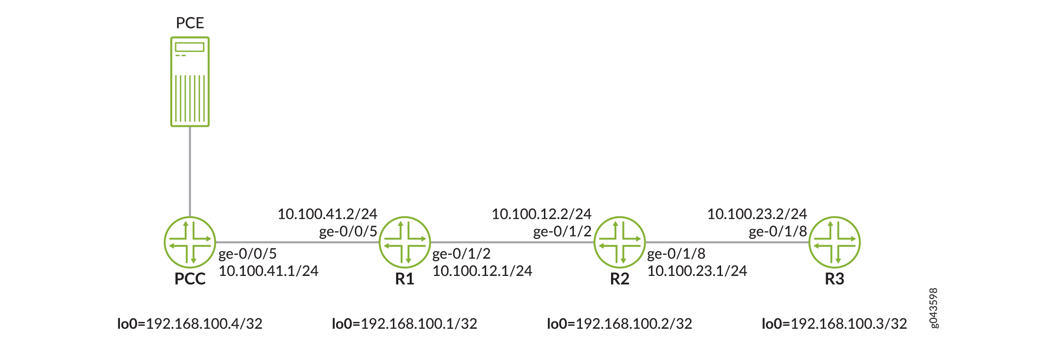
Configuration
CLI Quick Configuration
To quickly configure this example, copy the
following commands, paste them into a text file, remove any line breaks,
change any details necessary to match your network configuration,
copy and paste the commands into the CLI at the [edit] hierarchy
level, and then enter commit from configuration mode.
Although we present the configuration of all the devices (PCC and the three routers) in this section, the Step-by-Step procedure documents only the configuration of the PCC.
PCC
set interfaces ge-0/0/5 unit 0 family inet address 10.100.41.1/24 set interfaces ge-0/0/5 unit 0 family iso set interfaces ge-0/0/5 unit 0 family mpls set interfaces lo0 unit 0 family inet address 192.168.100.4/32 primary set interfaces lo0 unit 0 family iso address 49.0011.0110.0000.0101.00 set interfaces lo0 unit 0 family mpls set routing-options static route 100.1.1.1/32 next-hop 192.168.100.3 set routing-options router-id 192.168.100.4 set routing-options autonomous-system 64496 set protocols rsvp interface fxp0.0 disable set protocols rsvp interface all set protocols mpls lsp-external-controller pccd set protocols mpls interface all set protocols mpls interface fxp0.0 disable set protocols isis source-packet-routing srgb start-label 800000 set protocols isis source-packet-routing srgb index-range 4000 set protocols isis source-packet-routing node-segment ipv4-index 101 set protocols isis source-packet-routing node-segment ipv6-index 11 set protocols isis level 1 disable set protocols isis level 2 wide-metrics-only set protocols isis interface all point-to-point set protocols isis interface all level 2 metric 10 set protocols isis interface fxp0.0 disable set protocols isis interface lo0.0 passive set protocols source-packet-routing segment-list static_seg_list_1 hop1 label 800102 set protocols source-packet-routing segment-list static_seg_list_1 hop2 label 800103 set protocols source-packet-routing source-routing-path static_srte_lsp_1 to 192.168.100.3 set protocols source-packet-routing source-routing-path static_srte_lsp_1 primary static_seg_list_1 lsp-external-controller pccd set protocols spring-traffic-engineering lsp-external-controller pccd set protocols source-packet-routing source-routing-path static1 lsp-external-controller pccd set protocols pcep pce pce1 local-address 192.168.100.4 set protocols pcep pce pce1 destination-ipv4-address 10.102.180.232 set protocols pcep pce pce1 destination-port 4189 set protocols pcep pce pce1 pce-type active set protocols pcep pce pce1 pce-type stateful set protocols pcep pce pce1 lsp-provisioning set protocols pcep pce pce1 spring-capability
Router R1
set interfaces ge-0/0/5 unit 0 family inet address 10.100.41.2/24 set interfaces ge-0/0/5 unit 0 family iso set interfaces ge-0/0/5 unit 0 family mpls set interfaces ge-0/1/2 unit 0 family inet address 10.100.12.1/24 set interfaces ge-0/1/2 unit 0 family iso set interfaces ge-0/1/2 unit 0 family mpls set interfaces lo0 unit 0 family inet address 192.168.100.1/32 primary set interfaces lo0 unit 0 family iso address 49.0011.0110.0000.0102.00 set interfaces lo0 unit 0 family mpls set routing-options router-id 192.168.100.1 set routing-options autonomous-system 64496 set protocols rsvp interface all set protocols rsvp interface fxp0.0 disable set protocols mpls interface all set protocols mpls interface fxp0.0 disable set protocols isis source-packet-routing srgb start-label 800000 set protocols isis source-packet-routing srgb index-range 4000 set protocols isis source-packet-routing node-segment ipv4-index 102 set protocols isis level 1 disable set protocols isis level 2 wide-metrics-only set protocols isis interface all point-to-point set protocols isis interface all level 2 metric 10 set protocols isis interface fxp0.0 disable set protocols isis interface lo0.0 passive
Router R2
set interfaces ge-0/1/2 unit 0 family inet address 10.100.12.2/24 set interfaces ge-0/1/2 unit 0 family iso set interfaces ge-0/1/2 unit 0 family mpls set interfaces ge-0/1/8 unit 0 family inet address 10.100.23.1/24 set interfaces ge-0/1/8 unit 0 family iso set interfaces ge-0/1/8 unit 0 family mpls set interfaces lo0 unit 0 family inet address 192.168.100.2/32 set interfaces lo0 unit 0 family iso address 49.0011.0110.0000.0105.00 set interfaces lo0 unit 0 family mpls set routing-options router-id 192.168.100.2 set routing-options autonomous-system 64496 set protocols rsvp interface all set protocols rsvp interface fxp0.0 disable set protocols mpls interface all set protocols mpls interface fxp0.0 disable set protocols isis source-packet-routing srgb start-label 800000 set protocols isis source-packet-routing srgb index-range 4000 set protocols isis source-packet-routing node-segment ipv4-index 105 set protocols isis level 1 disable set protocols isis level 2 wide-metrics-only set protocols isis interface all point-to-point set protocols isis interface all level 2 metric 10 set protocols isis interface all level 1 disable set protocols isis interface fxp0.0 disable set protocols isis interface lo0.0 passive
Router R3
set interfaces ge-0/1/8 unit 0 family inet address 10.100.23.2/24 set interfaces ge-0/1/8 unit 0 family iso set interfaces ge-0/1/8 unit 0 family mpls set interfaces lo0 unit 0 family inet address 192.168.100.3/32 primary set interfaces lo0 unit 0 family iso address 49.0011.0110.0000.0103.00 set interfaces lo0 unit 0 family mpls set routing-options static route 100.1.1.1/32 receive set routing-options router-id 192.168.100.3 set routing-options autonomous-system 64496 set protocols rsvp interface all set protocols rsvp interface fxp0.0 disable set protocols mpls interface all set protocols mpls interface fxp0.0 disable set protocols isis source-packet-routing srgb start-label 800000 set protocols isis source-packet-routing srgb index-range 4000 set protocols isis source-packet-routing node-segment ipv4-index 103 set protocols isis level 1 disable set protocols isis level 2 wide-metrics-only set protocols isis interface all point-to-point set protocols isis interface all level 2 metric 10 set protocols isis interface fxp0.0 disable set protocols isis interface lo0.0 passive
Procedure
Step-by-Step Procedure
In this example, we configure only the PCC.
The following steps require that you navigate various levels in the configuration hierarchy. For information about navigating the CLI, see Using the CLI Editor in Configuration Mode in the CLI User Guide.
To configure the PCC:
Configure the interfaces of the PCC.
[edit interfaces] user@PCC# set ge-0/0/5 unit 0 family inet address 10.100.41.1/24 user@PCC# set ge-0/0/5 unit 0 family iso user@PCC# set ge-0/0/5 unit 0 family mpls user@PCC# set lo0 unit 0 family inet address 192.168.100.4/32 primary user@PCC# set lo0 unit 0 family iso address 49.0011.0110.0000.0101.00 user@PCC# set lo0 unit 0 family mpls
Configure the router ID and assign an autonomous system number for the PCC.
[edit routing-options] user@PCC# set router-id 192.168.100.4 user@PCC# set autonomous-system 64496
Configure a static route from the PCC to Router R3.
The static route is created for verification purpose only and does not affect the feature functionality.
[edit routing-options] user@PCC# set static route 100.1.1.1/32 next-hop 192.168.100.3
Configure RSVP on all the interfaces of the PCC, excluding the management interface.
[edit protocols] user@PCC# set rsvp interface fxp0.0 disable user@PCC# set rsvp interface all
Configure MPLS on all the interfaces of the PCC, excluding the management interface.
[edit protocols] user@PCC# set mpls interface all user@PCC# set mpls interface fxp0.0 disable
Enable external path computing capability for MPLS.
[edit protocols]
user@PCC# set mpls lsp-external-controller pccd
Configure IS-IS level 2 on all the interfaces of the PCC, excluding the management and loopback interfaces.
[edit protocols] user@PCC# set isis level 1 disable user@PCC# set isis level 2 wide-metrics-only user@PCC# set isis interface all point-to-point user@PCC# set isis interface all level 2 metric 10 user@PCC# set isis interface fxp0.0 disable user@PCC# set isis interface lo0.0 passive
Configure segment routing global block (SRGB) attributes for segment routing.
[edit protocols] user@PCC# set isis source-packet-routing srgb start-label 800000 user@PCC# set isis source-packet-routing srgb index-range 4000 user@PCC# set isis source-packet-routing node-segment ipv4-index 101 user@PCC# set isis source-packet-routing node-segment ipv6-index 11
Enable external path computing capability for SR-TE.
[edit protocols] user@PCC# set spring-traffic-engineering lsp-external-controller pccd
Configure the PCE parameters and enable provisioning of the LSP by the PCE and the segment routing capability.
[edit protocols] user@PCC# set pcep pce pce1 local-address 192.168.100.4 user@PCC# set pcep pce pce1 destination-ipv4-address 10.102.180.232 user@PCC# set pcep pce pce1 destination-port 4189 user@PCC# set pcep pce pce1 pce-type active user@PCC# set pcep pce pce1 pce-type stateful
Enable provisioning of segment routing LSPs by the PCE.
[edit protocols] user@PCC# set pcep pce pce1 lsp-provisioning
Enable segment routing capability for the PCE.
[edit protocols] user@PCC# set pcep pce pce1 spring-capability
Define the static segment list
static_seg_list_1parameters.[edit protocols] user@PCC# set source-packet-routing segment-list static_seg_list_1 hop1 label 800102 user@PCC# set source-packet-routing segment-list static_seg_list_1 hop2 label 800103
Configure a static segment routing LSP from the PCC to Router R3 for PCE delegation.
[edit protocols] user@PCC# set source-packet-routing source-routing-path static_srte_lsp_1 to 192.168.100.3
Enable delegation capability for the
static_srte_lsp_1source-routing path.[edit protocols] user@PCC# set source-packet-routing source-routing-path static_srte_lsp_1 primary static_seg_list_1 lsp-external-controller pccd
By completing Steps 13, 14, and 15, you enable the PCC to delegate the segment routing LSPs to the PCE.
Commit the configuration.
Results
From configuration mode, confirm your configuration
by entering the show interfaces, show routing-options, and show protocols commands. If the output does not
display the intended configuration, repeat the instructions in this
example to correct the configuration.
user@PCC# show interfaces
ge-0/0/5 {
unit 0 {
family inet {
address 10.100.41.1/24;
}
family iso;
family mpls;
}
}
lo0 {
unit 0 {
family inet {
address 192.168.100.4/32 {
primary;
}
}
family iso {
address 49.0011.0110.0000.0101.00;
}
family mpls;
}
}
user@PCC# show routing-options
static {
route 100.1.1.1/32 next-hop 192.168.100.3;
}
router-id 192.168.100.4;
autonomous-system 64496;
user@PCC# show protocols
rsvp {
interface fxp0.0 {
disable;
}
interface all;
}
mpls {
lsp-external-controller pccd;
interface all;
interface fxp0.0 {
disable;
}
}
isis {
source-packet-routing {
srgb start-label 800000 index-range 4000;
node-segment {
ipv4-index 101;
ipv6-index 11;
}
}
level 1 disable;
level 2 wide-metrics-only;
interface all {
point-to-point;
level 2 metric 10;
}
interface fxp0.0 {
disable;
}
interface lo0.0 {
passive;
}
}
spring-traffic-engineering {
lsp-external-controller pccd;
}
source-packet-routing {
segment-list static_seg_list_1 {
hop1 label 800102
hop1 label 800102
}
source-routing-path static_srte_lsp_1 {
to 192.168.100.3;
primary {
static_seg_list_1 {
lsp-external-controller pccd;
}
}
}
}
pcep {
pce pce1 {
local-address 192.168.100.4;
destination-ipv4-address 10.102.180.232;
destination-port 4189;
pce-type active stateful;
lsp-provisioning;
spring-capability;
}
}
If you are done configuring the device (the PCC), enter commit from configuration mode.
Verification
Confirm that the configuration is working properly.
- Verify IS-IS Adjacency and Labels
- Verify the Traffic Engineering Database
- Verify SR-TE LSPs
- Verify Tunnel Route Creation
- Verify Forwarding Table Entries
- Verify the Use of Tunnel Routes for Static Route Forwarding
Verify IS-IS Adjacency and Labels
Purpose
Verify the IS-IS adjacency on the PCC. Take note of the SRGB label range, adjacency and node segment values, and SPRING capability output fields.
Action
From operational mode, run the show isis adjacency
extensive, show isis database extensive, and show isis overview commands.
user@PCC> show isis adjacency extensive R1 Interface: ge-0/0/5.0, Level: 2, State: Up, Expires in 25 secs Priority: 0, Up/Down transitions: 1, Last transition: 00:37:15 ago Circuit type: 2, Speaks: IP, IPv6 Topologies: Unicast Restart capable: Yes, Adjacency advertisement: Advertise IP addresses: 10.100.41.2 Level 2 IPv4 Adj-SID: 16 Transition log: When State Event Down reason Wed Apr 5 02:42:48 Up Seenself PCE Interface: gre.0, Level: 2, State: Up, Expires in 25 secs Priority: 0, Up/Down transitions: 1, Last transition: 00:27:00 ago Circuit type: 2, Speaks: IP, IPv6 Topologies: Unicast Restart capable: Yes, Adjacency advertisement: Advertise IP addresses: 11.105.199.2 Level 2 Transition log: When State Event Down reason Wed Apr 5 02:53:03 Up Seenself
user@PCC> show isis database extensive
IS-IS level 1 link-state database:
IS-IS level 2 link-state database:
PCC.00-00 Sequence: 0x2a6, Checksum: 0x1a4f, Lifetime: 1150 secs
IPV4 Index: 101
Node Segment Blocks Advertised:
Start Index : 0, Size : 4000, Label-Range: [ 800000, 803999 ]
IS neighbor: R1.00 Metric: 10
Two-way fragment: R1.00-00, Two-way first fragment: R1.00-00
IS neighbor: PCE.00 Metric: 16777215
IP prefix: 192.168.100.4/32 Metric: 0 Internal Up
IP prefix: 11.101.102.0/30 Metric: 10 Internal Up
IP prefix: 11.105.199.0/30 Metric: 16777215 Internal Up
Header: LSP ID: PCC.00-00, Length: 243 bytes
Allocated length: 1492 bytes, Router ID: 192.168.100.4
Remaining lifetime: 1150 secs, Level: 2, Interface: 0
Estimated free bytes: 1084, Actual free bytes: 1249
Aging timer expires in: 1150 secs
Protocols: IP, IPv6
Packet: LSP ID: PCC.00-00, Length: 243 bytes, Lifetime : 1198 secs
Checksum: 0x1a4f, Sequence: 0x2a6, Attributes: 0x3 L1 L2
NLPID: 0x83, Fixed length: 27 bytes, Version: 1, Sysid length: 0 bytes
Packet type: 20, Packet version: 1, Max area: 0
TLVs:
Area address: 49.0011 (3)
LSP Buffer Size: 1492
Speaks: IP
Speaks: IPV6
IP router id: 192.168.100.4
IP address: 192.168.100.4
Hostname: PCC
IS extended neighbor: R1.00, Metric: default 10
IP address: 10.100.41.1
Neighbor's IP address: 10.100.41.2
Local interface index: 334, Remote interface index: 333
Current reservable bandwidth:
Priority 0 : 10Mbps
Priority 1 : 10Mbps
Priority 2 : 10Mbps
Priority 3 : 10Mbps
Priority 4 : 10Mbps
Priority 5 : 10Mbps
Priority 6 : 10Mbps
Priority 7 : 10Mbps
Maximum reservable bandwidth: 10Mbps
Maximum bandwidth: 10Mbps
Administrative groups: 0 none
P2P IPV4 Adj-SID - Flags:0x30(F:0,B:0,V:1,L:1,S:0), Weight:0, Label: 16
IS extended neighbor: PCE.00, Metric: default 16777215
IP address: 11.105.199.1
Neighbor's IP address: 11.105.199.2
Local interface index: 329, Remote interface index: 329
IP extended prefix: 11.101.102.0/30 metric 10 up
IP extended prefix: 11.105.199.0/30 metric 16777215 up
IP extended prefix: 192.168.100.4/32 metric 0 up
8 bytes of subtlvs
Node SID, Flags: 0x40(R:0,N:1,P:0,E:0,V:0,L:0), Algo: SPF(0), Value: 101
Router Capability: Router ID 192.168.100.4, Flags: 0x00
SPRING Capability - Flags: 0xc0(I:1,V:1), Range: 4000, SID-Label: 800000
SPRING Algorithm - Algo: 0
No queued transmissions
R1.00-00 Sequence: 0x297, Checksum: 0x1615, Lifetime: 839 secs
IPV4 Index: 102
Node Segment Blocks Advertised:
Start Index : 0, Size : 4000, Label-Range: [ 800000, 803999 ]
IS neighbor: PCC.00 Metric: 10
Two-way fragment: PCC.00-00, Two-way first fragment: PCC.00-00
IS neighbor: R2.00 Metric: 10
Two-way fragment: R2.00-00, Two-way first fragment: R2.00-00
IP prefix: 192.168.100.1/32 Metric: 0 Internal Up
IP prefix: 11.101.102.0/30 Metric: 10 Internal Up
IP prefix: 11.102.105.0/30 Metric: 10 Internal Up
Header: LSP ID: R1.00-00, Length: 302 bytes
Allocated length: 302 bytes, Router ID: 192.168.100.1
Remaining lifetime: 839 secs, Level: 2, Interface: 334
Estimated free bytes: 0, Actual free bytes: 0
Aging timer expires in: 839 secs
Protocols: IP, IPv6
Packet: LSP ID: R1.00-00, Length: 302 bytes, Lifetime : 1196 secs
Checksum: 0x1615, Sequence: 0x297, Attributes: 0x3 L1 L2
NLPID: 0x83, Fixed length: 27 bytes, Version: 1, Sysid length: 0 bytes
Packet type: 20, Packet version: 1, Max area: 0
TLVs:
Area address: 49.0011 (3)
LSP Buffer Size: 1492
Speaks: IP
Speaks: IPV6
IP router id: 192.168.100.1
IP address: 192.168.100.1
Hostname: R1
IP extended prefix: 192.168.100.1/32 metric 0 up
8 bytes of subtlvs
Node SID, Flags: 0x40(R:0,N:1,P:0,E:0,V:0,L:0), Algo: SPF(0), Value: 102
IP extended prefix: 11.101.102.0/30 metric 10 up
IP extended prefix: 11.102.105.0/30 metric 10 up
Router Capability: Router ID 192.168.100.1, Flags: 0x00
SPRING Capability - Flags: 0xc0(I:1,V:1), Range: 4000, SID-Label: 800000
SPRING Algorithm - Algo: 0
IS extended neighbor: R2.00, Metric: default 10
IP address: 10.100.12.1
Neighbor's IP address: 10.100.12.2
Local interface index: 334, Remote interface index: 333
Current reservable bandwidth:
Priority 0 : 10Mbps
Priority 1 : 10Mbps
Priority 2 : 10Mbps
Priority 3 : 10Mbps
Priority 4 : 10Mbps
Priority 5 : 10Mbps
Priority 6 : 10Mbps
Priority 7 : 10Mbps
Maximum reservable bandwidth: 10Mbps
Maximum bandwidth: 10Mbps
Administrative groups: 0 none
P2P IPV4 Adj-SID - Flags:0x30(F:0,B:0,V:1,L:1,S:0), Weight:0, Label: 17
IS extended neighbor: PCC.00, Metric: default 10
IP address: 10.100.41.2
Neighbor's IP address: 10.100.41.1
Local interface index: 333, Remote interface index: 334
Current reservable bandwidth:
Priority 0 : 10Mbps
Priority 1 : 10Mbps
Priority 2 : 10Mbps
Priority 3 : 10Mbps
Priority 4 : 10Mbps
Priority 5 : 10Mbps
Priority 6 : 10Mbps
Priority 7 : 10Mbps
Maximum reservable bandwidth: 10Mbps
Maximum bandwidth: 10Mbps
Administrative groups: 0 none
P2P IPV4 Adj-SID - Flags:0x30(F:0,B:0,V:1,L:1,S:0), Weight:0, Label: 16
No queued transmissions
R3.00-00 Sequence: 0x95, Checksum: 0xd459, Lifetime: 895 secs
IPV4 Index: 103
Node Segment Blocks Advertised:
Start Index : 0, Size : 4000, Label-Range: [ 800000, 803999 ]
IS neighbor: R2.00 Metric: 10
Two-way fragment: R2.00-00, Two-way first fragment: R2.00-00
IP prefix: 192.168.100.3/32 Metric: 0 Internal Up
IP prefix: 11.102.1.0/24 Metric: 10 Internal Up
IP prefix: 11.103.107.0/30 Metric: 10 Internal Up
Header: LSP ID: R3.00-00, Length: 209 bytes
Allocated length: 284 bytes, Router ID: 192.168.100.3
Remaining lifetime: 895 secs, Level: 2, Interface: 334
Estimated free bytes: 75, Actual free bytes: 75
Aging timer expires in: 895 secs
Protocols: IP, IPv6
Packet: LSP ID: R3.00-00, Length: 209 bytes, Lifetime : 1192 secs
Checksum: 0xd459, Sequence: 0x95, Attributes: 0x3 L1 L2
NLPID: 0x83, Fixed length: 27 bytes, Version: 1, Sysid length: 0 bytes
Packet type: 20, Packet version: 1, Max area: 0
TLVs:
Area address: 49.0011 (3)
LSP Buffer Size: 1492
Speaks: IP
Speaks: IPV6
IP router id: 192.168.100.3
IP address: 192.168.100.3
Hostname: R3
IS extended neighbor: R2.00, Metric: default 10
IP address: 10.100.23.2
Neighbor's IP address: 10.100.23.1
Local interface index: 336, Remote interface index: 334
Current reservable bandwidth:
Priority 0 : 10Mbps
Priority 1 : 10Mbps
Priority 2 : 10Mbps
Priority 3 : 10Mbps
Priority 4 : 10Mbps
Priority 5 : 10Mbps
Priority 6 : 10Mbps
Priority 7 : 10Mbps
Maximum reservable bandwidth: 10Mbps
Maximum bandwidth: 10Mbps
Administrative groups: 0 none
P2P IPV4 Adj-SID - Flags:0x30(F:0,B:0,V:1,L:1,S:0), Weight:0, Label: 16
IP extended prefix: 192.168.100.3/32 metric 0 up
8 bytes of subtlvs
Node SID, Flags: 0x40(R:0,N:1,P:0,E:0,V:0,L:0), Algo: SPF(0), Value: 103
IP extended prefix: 11.103.107.0/30 metric 10 up
IP extended prefix: 11.102.1.0/24 metric 10 up
Router Capability: Router ID 192.168.100.3, Flags: 0x00
SPRING Capability - Flags: 0xc0(I:1,V:1), Range: 4000, SID-Label: 800000
SPRING Algorithm - Algo: 0
No queued transmissions
R2.00-00 Sequence: 0x2aa, Checksum: 0xf8f4, Lifetime: 1067 secs
IPV4 Index: 105
Node Segment Blocks Advertised:
Start Index : 0, Size : 4000, Label-Range: [ 800000, 803999 ]
IS neighbor: R1.00 Metric: 10
Two-way fragment: R1.00-00, Two-way first fragment: R1.00-00
IS neighbor: R3.00 Metric: 10
Two-way fragment: R3.00-00, Two-way first fragment: R3.00-00
IP prefix: 192.168.100.2/32 Metric: 0 Internal Up
IP prefix: 11.102.105.0/30 Metric: 10 Internal Up
IP prefix: 11.103.107.0/30 Metric: 10 Internal Up
Header: LSP ID: R2.00-00, Length: 302 bytes
Allocated length: 302 bytes, Router ID: 192.168.100.2
Remaining lifetime: 1067 secs, Level: 2, Interface: 334
Estimated free bytes: 0, Actual free bytes: 0
Aging timer expires in: 1067 secs
Protocols: IP, IPv6
Packet: LSP ID: R2.00-00, Length: 302 bytes, Lifetime : 1194 secs
Checksum: 0xf8f4, Sequence: 0x2aa, Attributes: 0x3 L1 L2
NLPID: 0x83, Fixed length: 27 bytes, Version: 1, Sysid length: 0 bytes
Packet type: 20, Packet version: 1, Max area: 0
TLVs:
Area address: 49.0011 (3)
LSP Buffer Size: 1492
Speaks: IP
Speaks: IPV6
IP router id: 192.168.100.2
IP address: 192.168.100.2
Hostname: R2
IP extended prefix: 192.168.100.2/32 metric 0 up
8 bytes of subtlvs
Node SID, Flags: 0x40(R:0,N:1,P:0,E:0,V:0,L:0), Algo: SPF(0), Value: 105
IP extended prefix: 11.102.105.0/30 metric 10 up
IP extended prefix: 11.103.107.0/30 metric 10 up
Router Capability: Router ID 192.168.100.2, Flags: 0x00
SPRING Capability - Flags: 0xc0(I:1,V:1), Range: 4000, SID-Label: 800000
SPRING Algorithm - Algo: 0
IS extended neighbor: R3.00, Metric: default 10
IP address: 10.100.23.1
Neighbor's IP address: 10.100.23.2
Local interface index: 334, Remote interface index: 336
Current reservable bandwidth:
Priority 0 : 10Mbps
Priority 1 : 10Mbps
Priority 2 : 10Mbps
Priority 3 : 10Mbps
Priority 4 : 10Mbps
Priority 5 : 10Mbps
Priority 6 : 10Mbps
Priority 7 : 10Mbps
Maximum reservable bandwidth: 10Mbps
Maximum bandwidth: 10Mbps
Administrative groups: 0 none
P2P IPV4 Adj-SID - Flags:0x30(F:0,B:0,V:1,L:1,S:0), Weight:0, Label: 16
IS extended neighbor: R1.00, Metric: default 10
IP address: 10.100.12.2
Neighbor's IP address: 10.100.12.1
Local interface index: 333, Remote interface index: 334
Current reservable bandwidth:
Priority 0 : 10Mbps
Priority 1 : 10Mbps
Priority 2 : 10Mbps
Priority 3 : 10Mbps
Priority 4 : 10Mbps
Priority 5 : 10Mbps
Priority 6 : 10Mbps
Priority 7 : 10Mbps
Maximum reservable bandwidth: 10Mbps
Maximum bandwidth: 10Mbps
Administrative groups: 0 none
P2P IPV4 Adj-SID - Flags:0x30(F:0,B:0,V:1,L:1,S:0), Weight:0, Label: 17
No queued transmissions
PCE.00-00 Sequence: 0x277, Checksum: 0x64a5, Lifetime: 533 secs
IS neighbor: PCC.00 Metric: 16777215
IP prefix: 11.0.0.199/32 Metric: 0 Internal Up
IP prefix: 11.105.199.0/30 Metric: 16777215 Internal Up
Header: LSP ID: PCE.00-00, Length: 120 bytes
Allocated length: 284 bytes, Router ID: 11.0.0.199
Remaining lifetime: 533 secs, Level: 2, Interface: 329
Estimated free bytes: 164, Actual free bytes: 164
Aging timer expires in: 533 secs
Protocols: IP, IPv6
Packet: LSP ID: PCE.00-00, Length: 120 bytes, Lifetime : 1196 secs
Checksum: 0x64a5, Sequence: 0x277, Attributes: 0x3 L1 L2
NLPID: 0x83, Fixed length: 27 bytes, Version: 1, Sysid length: 0 bytes
Packet type: 20, Packet version: 1, Max area: 0
TLVs:
Area address: 11.0007 (3)
LSP Buffer Size: 1492
Speaks: IP
Speaks: IPV6
IP router id: 11.0.0.199
IP address: 11.0.0.199
Hostname: PCE
Router Capability: Router ID 11.0.0.199, Flags: 0x00
IP extended prefix: 11.105.199.0/30 metric 16777215 up
IP extended prefix: 11.0.0.199/32 metric 0 up
IS extended neighbor: PCC.00, Metric: default 16777215
IP address: 11.105.199.2
Neighbor's IP address: 11.105.199.1
Local interface index: 329, Remote interface index: 329
No queued transmissionsuser@PCC> show isis overview
Instance: master
Router ID: 192.168.100.4
Hostname: PCC
Sysid: 0110.0000.0101
Areaid: 49.0011
Adjacency holddown: enabled
Maximum Areas: 3
LSP life time: 1200
Attached bit evaluation: enabled
SPF delay: 200 msec, SPF holddown: 5000 msec, SPF rapid runs: 3
IPv4 is enabled, IPv6 is enabled, SPRING based MPLS is enabled
Traffic engineering: enabled
Restart: Disabled
Helper mode: Enabled
Layer2-map: Disabled
Source Packet Routing (SPRING): Enabled
SRGB Config Range:
SRGB Start-Label : 800000, SRGB Index-Range : 4000
SRGB Block Allocation: Success
SRGB Start Index : 800000, SRGB Size : 4000, Label-Range: [ 800000, 803999 ]
Node Segments: Enabled
Ipv4 Index : 101, Ipv6 Index : 11
Level 1
Internal route preference: 15
External route preference: 160
Prefix export count: 0
Wide metrics are enabled, Narrow metrics are enabled
Source Packet Routing is enabled
Level 2
Internal route preference: 18
External route preference: 165
Prefix export count: 0
Wide metrics are enabled
Source Packet Routing is enabledMeaning
The IS-IS adjacency between the PCC and PCE and that between the PCC and Router R1 are up and operational. The output also displays the label assignments for the adjacent and node segments.
Verify the Traffic Engineering Database
Purpose
Verify the traffic engineering database entries on the PCC.
Action
From operational mode, run the show ted database
extensive command.
user@PCC# show ted database extensive
TED database: 5 ISIS nodes 5 INET nodes
NodeID: PCC.00(192.168.100.4)
Type: Rtr, Age: 403 secs, LinkIn: 1, LinkOut: 1
Protocol: IS-IS(2)
192.168.100.4
To: R1.00(192.168.100.1), Local: 10.100.41.1, Remote: 10.100.41.2
Local interface index: 334, Remote interface index: 333
Color: 0 none
Metric: 10
IGP metric: 10
Static BW: 10Mbps
Reservable BW: 10Mbps
Available BW [priority] bps:
[0] 10Mbps [1] 10Mbps [2] 10Mbps [3] 10Mbps
[4] 10Mbps [5] 10Mbps [6] 10Mbps [7] 10Mbps
Interface Switching Capability Descriptor(1):
Switching type: Packet
Encoding type: Packet
Maximum LSP BW [priority] bps:
[0] 10Mbps [1] 10Mbps [2] 10Mbps [3] 10Mbps
[4] 10Mbps [5] 10Mbps [6] 10Mbps [7] 10Mbps
P2P Adjacency-SID:
IPV4, SID: 16, Flags: 0x30, Weight: 0
Prefixes:
192.168.100.4/32
Metric: 0, Flags: 0x00
Prefix-SID:
SID: 101, Flags: 0x40, Algo: 0
SPRING-Capabilities:
SRGB block [Start: 800000, Range: 4000, Flags: 0xc0]
SPRING-Algorithms:
Algo: 0
NodeID: R1.00(192.168.100.1)
Type: Rtr, Age: 712 secs, LinkIn: 2, LinkOut: 2
Protocol: IS-IS(2)
192.168.100.1
To: PCC.00(192.168.100.4), Local: 10.100.41.2, Remote: 10.100.41.1
Local interface index: 333, Remote interface index: 334
Color: 0 none
Metric: 10
IGP metric: 10
Static BW: 10Mbps
Reservable BW: 10Mbps
Available BW [priority] bps:
[0] 10Mbps [1] 10Mbps [2] 10Mbps [3] 10Mbps
[4] 10Mbps [5] 10Mbps [6] 10Mbps [7] 10Mbps
Interface Switching Capability Descriptor(1):
Switching type: Packet
Encoding type: Packet
Maximum LSP BW [priority] bps:
[0] 10Mbps [1] 10Mbps [2] 10Mbps [3] 10Mbps
[4] 10Mbps [5] 10Mbps [6] 10Mbps [7] 10Mbps
P2P Adjacency-SID:
IPV4, SID: 16, Flags: 0x30, Weight: 0
To: R2.00(192.168.100.2), Local: 10.100.12.1, Remote: 10.100.12.2
Local interface index: 334, Remote interface index: 333
Color: 0 none
Metric: 10
IGP metric: 10
Static BW: 10Mbps
Reservable BW: 10Mbps
Available BW [priority] bps:
[0] 10Mbps [1] 10Mbps [2] 10Mbps [3] 10Mbps
[4] 10Mbps [5] 10Mbps [6] 10Mbps [7] 10Mbps
Interface Switching Capability Descriptor(1):
Switching type: Packet
Encoding type: Packet
Maximum LSP BW [priority] bps:
[0] 10Mbps [1] 10Mbps [2] 10Mbps [3] 10Mbps
[4] 10Mbps [5] 10Mbps [6] 10Mbps [7] 10Mbps
P2P Adjacency-SID:
IPV4, SID: 17, Flags: 0x30, Weight: 0
Prefixes:
192.168.100.1/32
Metric: 0, Flags: 0x00
Prefix-SID:
SID: 102, Flags: 0x40, Algo: 0
SPRING-Capabilities:
SRGB block [Start: 800000, Range: 4000, Flags: 0xc0]
SPRING-Algorithms:
Algo: 0
NodeID: R3.00(192.168.100.3)
Type: Rtr, Age: 435 secs, LinkIn: 1, LinkOut: 1
Protocol: IS-IS(2)
192.168.100.3
To: R2.00(192.168.100.2), Local: 10.100.23.2, Remote: 10.100.23.1
Local interface index: 336, Remote interface index: 334
Color: 0 none
Metric: 10
IGP metric: 10
Static BW: 10Mbps
Reservable BW: 10Mbps
Available BW [priority] bps:
[0] 10Mbps [1] 10Mbps [2] 10Mbps [3] 10Mbps
[4] 10Mbps [5] 10Mbps [6] 10Mbps [7] 10Mbps
Interface Switching Capability Descriptor(1):
Switching type: Packet
Encoding type: Packet
Maximum LSP BW [priority] bps:
[0] 10Mbps [1] 10Mbps [2] 10Mbps [3] 10Mbps
[4] 10Mbps [5] 10Mbps [6] 10Mbps [7] 10Mbps
P2P Adjacency-SID:
IPV4, SID: 16, Flags: 0x30, Weight: 0
Prefixes:
192.168.100.3/32
Metric: 0, Flags: 0x00
Prefix-SID:
SID: 103, Flags: 0x40, Algo: 0
SPRING-Capabilities:
SRGB block [Start: 800000, Range: 4000, Flags: 0xc0]
SPRING-Algorithms:
Algo: 0
NodeID: R2.00(192.168.100.2)
Type: Rtr, Age: 456 secs, LinkIn: 2, LinkOut: 2
Protocol: IS-IS(2)
192.168.100.2
To: R1.00(192.168.100.1), Local: 10.100.12.2, Remote: 10.100.12.1
Local interface index: 333, Remote interface index: 334
Color: 0 none
Metric: 10
IGP metric: 10
Static BW: 10Mbps
Reservable BW: 10Mbps
Available BW [priority] bps:
[0] 10Mbps [1] 10Mbps [2] 10Mbps [3] 10Mbps
[4] 10Mbps [5] 10Mbps [6] 10Mbps [7] 10Mbps
Interface Switching Capability Descriptor(1):
Switching type: Packet
Encoding type: Packet
Maximum LSP BW [priority] bps:
[0] 10Mbps [1] 10Mbps [2] 10Mbps [3] 10Mbps
[4] 10Mbps [5] 10Mbps [6] 10Mbps [7] 10Mbps
P2P Adjacency-SID:
IPV4, SID: 17, Flags: 0x30, Weight: 0
To: R3.00(192.168.100.3), Local: 10.100.23.1, Remote: 10.100.23.2
Local interface index: 334, Remote interface index: 336
Color: 0 none
Metric: 10
IGP metric: 10
Static BW: 10Mbps
Reservable BW: 10Mbps
Available BW [priority] bps:
[0] 10Mbps [1] 10Mbps [2] 10Mbps [3] 10Mbps
[4] 10Mbps [5] 10Mbps [6] 10Mbps [7] 10Mbps
Interface Switching Capability Descriptor(1):
Switching type: Packet
Encoding type: Packet
Maximum LSP BW [priority] bps:
[0] 10Mbps [1] 10Mbps [2] 10Mbps [3] 10Mbps
[4] 10Mbps [5] 10Mbps [6] 10Mbps [7] 10Mbps
P2P Adjacency-SID:
IPV4, SID: 16, Flags: 0x30, Weight: 0
Prefixes:
192.168.100.2/32
Metric: 0, Flags: 0x00
Prefix-SID:
SID: 105, Flags: 0x40, Algo: 0
SPRING-Capabilities:
SRGB block [Start: 800000, Range: 4000, Flags: 0xc0]
SPRING-Algorithms:
Algo: 0
NodeID: PCE.00(11.0.0.199)
Type: Rtr, Age: 267 secs, LinkIn: 0, LinkOut: 0
Protocol: IS-IS(2)
11.0.0.199Meaning
The traffic engineering database includes entries advertised from Routers R1, R2, and R3, which the PCE uses for external path computing for the PCC.
Verify SR-TE LSPs
Purpose
Verify the creation of SR-TE LSPs on the PCC.
Action
From operational mode, run the show path-computation-client
lsp, show spring-traffic-engineering lsp detail,
and show route protocol spring-te commands.
user@PCC> show path-computation-client lsp Name Status PLSP-Id LSP-Type Controller Path-Setup-Type Template adj_sid_lsp (Up) 3 ext-provised pce1 spring-te node_sid_lsp (Up) 5 ext-provised pce1 spring-te
user@PCC> show spring-traffic-engineering lsp detail
Name: adj_sid_lsp
To: 192.168.100.3
State: Up, Outgoing interface: ge-0/0/5.0
Delegation info:
Control-status: Externally controlled
Routing-status: Externally routed
SR-ERO hop count: 3
Hop 1 (Strict):
NAI: IPv4 Adjacency ID, 10.100.41.1 -> 10.100.41.2
SID type: 20-bit label, Value: 16
Hop 2 (Strict):
NAI: IPv4 Adjacency ID, 10.100.12.1 -> 10.100.12.2
SID type: 20-bit label, Value: 17
Hop 3 (Strict):
NAI: IPv4 Adjacency ID, 10.100.23.1 -> 10.100.23.2
SID type: 20-bit label, Value: 16
Name: node_sid_lsp
To: 192.168.100.3
State: Up, Outgoing interface: ge-0/0/5.0
Delegation info:
Control-status: Externally controlled
Routing-status: Externally routed
SR-ERO hop count: 3
Hop 1 (Strict):
NAI: IPv4 Adjacency ID, 10.100.41.1 -> 10.100.41.2
SID type: 20-bit label, Value: 16
Hop 2 (Strict):
NAI: IPv4 Node ID, Node address: 192.168.100.1
SID type: 20-bit label, Value: 800105
Hop 3 (Strict):
NAI: IPv4 Node ID, Node address: 192.168.100.2
SID type: 20-bit label, Value: 800103
Name: static_srte_lsp_1
Tunnel-source: Static configuration
To: 192.168.100.3
State: Up
Path: static_seg_list_1
Outgoing interface: NA
Delegation info:
Control-status: Externally controlled
Routing-status: Externally routed
Auto-translate status: Disabled Auto-translate result: N/A
BFD status: Up BFD name: V4-srte_bfd_session-4
SR-ERO hop count: 2
Hop 1 (Strict):
NAI: IPv4 Adjacency ID, 13.1.1.2 -> 36.12.16.1
SID type: None
Hop 2 (Strict):
NAI: IPv4 Node ID, Node address: 192.168.100.3
SID type: 20-bit label, Value: 804000
Total displayed LSPs: 3 (Up: 3, Down: 0)user@PCC> show route protocol spring-te
inet.0: 17 destinations, 17 routes (17 active, 0 holddown, 0 hidden)
inet.3: 3 destinations, 4 routes (3 active, 0 holddown, 0 hidden)
+ = Active Route, - = Last Active, * = Both
192.168.100.3/32 *[SPRING-TE/8] 00:23:32, metric 0
to 10.100.41.2 via ge-0/0/5.0, Push 16, Push 17(top)
> to 10.100.41.2 via ge-0/0/5.0, Push 800103, Push 800105(top)
iso.0: 1 destinations, 1 routes (1 active, 0 holddown, 0 hidden)
mpls.0: 12 destinations, 12 routes (12 active, 0 holddown, 0 hidden)
inet6.0: 1 destinations, 1 routes (1 active, 0 holddown, 0 hidden)Meaning
The outputs show that two SR-TE LSPs—adj_sid_lsp and node_sid_lsp—have been created by the PCE for
the adjacency and node segments, respectively.
The segment routing LSP, static_srte_lsp_1, is enabled
with the delegation capability. The Delegation info field
shows the control and routing status of PCE-delegated LSPs. Externally controlled signifies that the PCE has
control over the LSPs. Externally routed signifies that the PCE has provided the ERO for the source-routing
path.
Verify Tunnel Route Creation
Purpose
Verify the tunnel routes created for the SR-TE LSPs that are included in the inet.3 routing table on the PCC.
Action
From operation mode, run the show route table inet.3
extensive command.
user@PCC> show route table inet.3 extensive
inet.3: 3 destinations, 4 routes (3 active, 0 holddown, 0 hidden)
192.168.100.1/32 (1 entry, 1 announced)
*L-ISIS Preference: 14
Level: 2
Next hop type: Router, Next hop index: 581
Address: 0xb7a23b0
Next-hop reference count: 13
Next hop: 10.100.41.2 via ge-0/0/5.0, selected
Session Id: 0x172
State: Active Int
Local AS: 64496
Age: 45:51 Metric: 10
Validation State: unverified
ORR Generation-ID: 0
Task: IS-IS
Announcement bits (2): 0-Resolve tree 1 2-Resolve tree 3
AS path: I
192.168.100.3/32 (2 entries, 1 announced)
*SPRING-TE Preference: 8
Next hop type: Router, Next hop index: 0
Address: 0xb61c190
Next-hop reference count: 7
Next hop: 10.100.41.2 via ge-0/0/5.0 weight 0x1
Label operation: Push 16, Push 17(top)
Label TTL action: prop-ttl, prop-ttl(top)
Load balance label: Label 16: None; Label 17: None;
Label element ptr: 0xb7a2a60
Label parent element ptr: 0x0
Label element references: 5
Label element child references: 0
Label element lsp id: 0
Session Id: 0x0
Next hop: 10.100.41.2 via ge-0/0/5.0 weight 0x1, selected
Label operation: Push 800103, Push 800105(top)
Label TTL action: prop-ttl, prop-ttl(top)
Load balance label: Label 800103: None; Label 800105: None;
Label element ptr: 0xb7a2c40
Label parent element ptr: 0x0
Label element references: 2
Label element child references: 0
Label element lsp id: 0
Session Id: 0x0
State: Active Int
Local AS: 64496
Age: 9:44 Metric: 0
Validation State: unverified
Task: SPRING-TE
Announcement bits (2): 0-Resolve tree 1 2-Resolve tree 3
AS path: I
L-ISIS Preference: 14
Level: 2
Next hop type: Router, Next hop index: 0
Address: 0xb7a28f0
Next-hop reference count: 1
Next hop: 10.100.41.2 via ge-0/0/5.0, selected
Label operation: Push 800103
Label TTL action: prop-ttl
Load balance label: Label 800103: None;
Label element ptr: 0xb7a2880
Label parent element ptr: 0x0
Label element references: 1
Label element child references: 0
Label element lsp id: 0
Session Id: 0x0
State: Int
Inactive reason: Route Preference
Local AS: 64496
Age: 45:40 Metric: 30
Validation State: unverified
ORR Generation-ID: 0
Task: IS-IS
AS path: I
192.168.100.2/32 (1 entry, 1 announced)
*L-ISIS Preference: 14
Level: 2
Next hop type: Router, Next hop index: 0
Address: 0xb7a29b0
Next-hop reference count: 1
Next hop: 10.100.41.2 via ge-0/0/5.0, selected
Label operation: Push 800105
Label TTL action: prop-ttl
Load balance label: Label 800105: None;
Label element ptr: 0xb7a2940
Label parent element ptr: 0x0
Label element references: 1
Label element child references: 0
Label element lsp id: 0
Session Id: 0x0
State: Active Int
Local AS: 64496
Age: 45:40 Metric: 20
Validation State: unverified
ORR Generation-ID: 0
Task: IS-IS
Announcement bits (2): 0-Resolve tree 1 2-Resolve tree 3
AS path: IMeaning
Tunnel routes have been created for the PCE-controlled LSP destination with SR-TE as the protocol label.
Verify Forwarding Table Entries
Purpose
Verify that the SR-TE LSP destination to Router R3 is installed in the forwarding table of the PCC.
Action
From operation mode, run the show route forwarding-table
destination ip-address extensive command.
user@PCC> show route forwarding-table destination 192.168.100.3 extensive
Routing table: default.inet [Index 0]
Internet:
Enabled protocols: Bridging,
Destination: 192.168.100.3/32
Route type: user
Route reference: 0 Route interface-index: 0
Multicast RPF nh index: 0
P2mpidx: 0
Flags: sent to PFE, rt nh decoupled
Nexthop: 10.100.41.2
Next-hop type: unicast Index: 581 Reference: 14
Next-hop interface: ge-0/0/5.0
Routing table: __pfe_private__.inet [Index 3]
Internet:
Enabled protocols: Bridging,
Destination: default
Route type: permanent
Route reference: 0 Route interface-index: 0
Multicast RPF nh index: 0
P2mpidx: 0
Flags: sent to PFE
Next-hop type: discard Index: 517 Reference: 2
Routing table: __juniper_services__.inet [Index 5]
Internet:
Enabled protocols: Bridging,
Destination: default
Route type: permanent
Route reference: 0 Route interface-index: 0
Multicast RPF nh index: 0
P2mpidx: 0
Flags: sent to PFE
Next-hop type: discard Index: 530 Reference: 2
Routing table: __master.anon__.inet [Index 6]
Internet:
Enabled protocols: Bridging, Dual VLAN,
Destination: default
Route type: permanent
Route reference: 0 Route interface-index: 0
Multicast RPF nh index: 0
P2mpidx: 0
Flags: sent to PFE
Next-hop type: reject Index: 545 Reference: 1 Meaning
The SR-TE LSP destination IP address to Router R3 is installed as a forwarding entry.
Verify the Use of Tunnel Routes for Static Route Forwarding
Purpose
Verify that the static route is taking the tunnel route created for the SR-TE LSPs.
Action
From operational mode, run the show route ip-address and show route forwarding-table
destination ip-address commands.
user@PCC> show route 100.1.1.1
inet.0: 17 destinations, 17 routes (17 active, 0 holddown, 0 hidden)
+ = Active Route, - = Last Active, * = Both
100.1.1.1/32 *[Static/5] 00:33:36, metric2 0
> to 10.100.41.2 via ge-0/0/5.0, Push 16, Push 17(top)
to 10.100.41.2 via ge-0/0/5.0, Push 800103, Push 800105(top)user@PCC> show route forwarding-table destination 100.1.1.1
Routing table: default.inet
Internet:
Enabled protocols: Bridging,
Destination Type RtRef Next hop Type Index NhRef Netif
100.1.1.1/32 user 0 indr 1048575 2
10.100.41.2 Push 16, Push 17(top) 590 2 ge-0/0/5.0
Routing table: __pfe_private__.inet
Internet:
Enabled protocols: Bridging,
Destination Type RtRef Next hop Type Index NhRef Netif
default perm 0 dscd 517 2
Routing table: __juniper_services__.inet
Internet:
Enabled protocols: Bridging,
Destination Type RtRef Next hop Type Index NhRef Netif
default perm 0 dscd 530 2
Routing table: __master.anon__.inet
Internet:
Enabled protocols: Bridging, Dual VLAN,
Destination Type RtRef Next hop Type Index NhRef Netif
default perm 0 rjct 545 1Meaning
The outputs show that the static route to Router R3 uses the tunnel route created for the SR-TE LSP.
Static Segment Routing Label Switched Path
The segment routing architecture enables the ingress devices in a core network to steer traffic through explicit paths. You can configure these paths using segment lists to define the paths that the incoming traffic should take. The incoming traffic may be labeled or IP traffic, causing the forwarding operation at the ingress device to be either a label swap, or a destination-based lookup.
- Understanding Static Segment Routing LSP in MPLS Networks
- Example: Configuring Static Segment Routing Label Switched Path
Understanding Static Segment Routing LSP in MPLS Networks
Source packet routing or segment routing is a control-plane architecture that enables an ingress router to steer a packet through a specific set of nodes and links in the network without relying on the intermediate nodes in the network to determine the actual path it should take.
- Introduction to Segment Routing LSPs
- Benefits of using Segment Routing LSPs
- Colored Static Segment Routing LSP
- Non-Colored Static Segment Routing LSP
- Static Segment Routing LSP Provisioning
- Static Segment Routing LSP Limitations
- Dynamic Creation of Segment Routing LSPs
- Color-Based Mapping of VPN Services
- Tunnel Templates for PCE-Initiated Segment Routing LSPs
Introduction to Segment Routing LSPs
Segment routing leverages the source routing paradigm. A device steers a packet through an ordered list of instructions, called segments. A segment can represent any instruction, topological or service-based. A segment can have a local semantic to a segment routing node or to a global node within a segment routing domain. Segment routing enforces a flow through any topological path and service chain while maintaining per-flow state only at the ingress device to the segment routing domain. Segment routing can be directly applied to the MPLS architecture with no change on the forwarding plane. A segment is encoded as an MPLS label. An ordered list of segments is encoded as a stack of labels. The segment to process is on the top of the stack. Upon completion of a segment, the related label is popped from the stack.
Segment routing LSPs can either be dynamic or static in nature.
|
Dynamic segment routing LSPs—When a segment routing LSP is created either by an external controller and downloaded to an ingress device through Path Computation Element Protocol (PCEP) extensions, or from a BGP segment routing policy through BGP segment routing extensions, the LSP is dynamically provisioned. The segment list of the dynamic segment routing LSP is contained in the PCEP Explicit Route Object (ERO), or the BGP segment routing policy of the LSP. |
|
Static segment routing LSPs—When a segment routing LSP is created on the ingress device through local configuration, the LSP is statically provisioned. A static segment routing LSP can further be classified as colored
and non-colored LSPs based on the configuration of the
For example: [edit protocols]
source-packet-routing {
source-routing-path lsp_name {
to destination_address;
color color_value;
binding-sid binding-label;
primary segment_list_1_name weight weight;
...
primary segment_list_n_name weight weight;
secondary segment_list_n_name;
sr-preference sr_preference_value;
}
}
Here, each primary and secondary statement refers to a segment list. [edit protocols]
source-packet-routing {
segment-list segment_list_name {
hop_1_name label sid_label;
...
hop_n_name label sid_label;
}
}
|
Benefits of using Segment Routing LSPs
-
Static segment routing does not rely on per LSP forwarding state on transit routers. Hence, removing the need of provisioning and maintaining per LSP forwarding state in the core.
-
Provide higher scalability to MPLS networks.
Colored Static Segment Routing LSP
A static segment routing LSP configured with the color statement is
called a colored LSP.
Understanding Colored Static Segment Routing LSPs
Similar to a BGP segment routing policy, the ingress route of the colored LSP is
installed in the inetcolor.0 or inet6color.0
routing tables, with destination-ip-address, color as key for
mapping IP traffic.
A static colored segment routing LSP may have a binding SID, for which a route is
installed in the mpls.0 routing table. This binding SID label
is used to map labeled traffic to the segment routing LSP. The gateways of the
route are derived from the segment list configurations under the primary and
secondary paths.
Segment List of Colored Segment Routing LSPs
The colored static segment routing LSPs already provide support for first hop label mode of resolving an LSP. However, first hop IP mode is not supported for colored segment routing LSPs. Starting in Junos OS Release 19.1R1, a commit check feature is introduced to ensure that all the segment lists contributing to the colored routes have the minimum label present for all hops. If this requirement is not met, the commit is blocked.
Non-Colored Static Segment Routing LSP
A static segment routing LSP that is configured without the color
statement is a non-colored LSP. Similar to PCEP segment routing tunnels, the ingress
route is installed in the inet.3 or inet6.3
routing tables.
Junos OS supports non-colored static segment routing LSPs on ingress routers. You can provision non-colored static segment routing LSP by configuring one source routed path and one or more segment lists. These segment lists can be used by multiple non-colored segment routing LSPs.
Understanding Non-Colored Segment Routing LSPs
The non-colored segment routing LSP has a unique name and a destination IP address. An ingress route to the destination is installed in the inet.3 routing table with a default preference of 8 and a metric of 1. This route allows non-colored services to be mapped to the segment routing LSP pertaining to the destination. In case the non-colored segment routing LSP does not require an ingress route then the ingress route can be disabled. A non-colored segment routing LSP uses binding SID label to achieve segment routing LSP stitching. This label that can be used to model the segment routing LSP as a segment that may be further used to construct other segment routing LSPs in a hierarchical manner. The transit of the binding SID label, by default, has a preference of 8 and a metric of 1.
Starting in Junos OS Release 18.2R1, statically configured non-colored segment routing LSPs on the ingress device are reported to the Path Computation Element (PCE) through a Path Computation Element Protocol (PCEP) session. These non-colored segment routing LSPs may have binding service identifier (SID) labels associated with them. With this feature, the PCE can use this binding SID label in the label stack to provision PCE-initiated segment routing LSP paths.
A non-colored segment routing LSP can have a maximum of 8 primary paths. If there
are multiple operational primary paths then the packet forwarding engine (PFE)
distributes traffic over the paths based on the load balancing factors like the
weight configured on the path. This is equal cost multi path (ECMP) if none of
the paths have a weight configured on them or weighted ECMP if at least one of
the paths has a non-zero weight configured on the paths. In both the cases, when
one or some of the paths fail, the PFE rebalances the traffic over the remaining
paths that automatically leads to achieving path protection. A non-colored
segment routing LSP can have a secondary path for dedicated path protection.
Upon failure of a primary path, the PFE rebalances the traffic to the remaining
functional primary paths. Otherwise, the PFE switches the traffic to the backup
path, hence achieving path protection. A non-colored segment routing LSP may
specify a metric at [edit protocols source-packet-routing
source-routing-path lsp-name] for its ingress
and binding-SID routes. Multiple non-colored segment routing LSPs have the same
destination address that contribute to the next hop of the ingress route.
Multiple non-colored segment routing LSPs have the same destination address that contribute to the next hop of the ingress route. Each path ,either primary or secondary, of each segment routing LSP is considered as a gateway candidate, if the path is functional and the segment routing LSP has the best preference of all these segment routing LSPs. However, the maximum number of gateways that the next-hop can hold cannot exceed the RPD multi-path limit, which is 128 by default. Extra paths are pruned, firstly secondary paths and then primary paths. A given segment list may be referred multiple times as primary or secondary paths by these segment routing LSPs. In this case, there are multiple gateways, each having a unique segment routing LSP tunnel ID. These gateways are distinct, although they have identical outgoing label stack and interface. A non-colored segment routing LSP and a colored segment routing LSP may also have the same destination address. However, they correspond to different destination addresses for ingress routes, as the colored segment routing LSP’s destination address is constructed with both its destination address and color.
In the case where a static non-colored segment routing LSP and a PCEP-created segment routing LSP co-exist and have the same to address that contributes to the same ingress route, if they also have the same preference. Otherwise, the segment routing LSP with the best preference is installed for the route.
Segment List of Non-Colored Segment Routing LSPs
A segment list consists of a list of hops. These hops are based on the SID label
or an IP address. The number of SID labels in the segment list should not exceed
the maximum segment list limit. Maximum segment-list binding to a LSP tunnel is
increased from 8 to 128, with maximum 1000 tunnels per system. A maximum of 128
primary paths are supported per static segment routing LSP. You can configure
the maximum segment list limit at the [edit protocols source-packet-routing] hierarchy level.
Prior to Junos OS Release 19.1R1, for a non-colored static segment routing LSP to be usable, the first hop of the segment list had to be an IP address of an outgoing interface and the second to nth hops could be SID labels. Starting in Junos OS Release 19.1R1, this requirement does not apply, as the first hop of the non-colored static LSPs now provides support for SID labels, in addition to IP addresses. With the first hop label support, MPLS fast reroute (FRR) and weighted equal-cost multipath is enabled for resolving the static non-colored segment routing LSPs, similar to colored static LSPs.
For the first-hop label mode to take effect, you must include the
inherit-label-nexthops statement globally or individually
for a segment list, and the first hop of the segment list must include both IP
address and label. If the first hop includes only IP address, the
inherit-label-nexthops statement does not have any
effect.
You can configure inherit-label-nexthops at any one of the
following hierarchies. The inherit-label-nexthops statement
takes effect only if the segment list first hop includes both IP address and
label.
-
Segment list level—At the
[edit protocols source-packet-routing segment-list segment-list-name]hierarchy level. -
Globally—At the
[edit protocols source-packet-routing]hierarchy level.
When the inherit-label-nexthops statement is configured
globally, it takes precedence over the segment-list level configuration, and the
inherit-label-nexthops configuration is applied to all the
segment lists. When the inherit-label-nexthops statement is not
configured globally, only segment lists with both labels and IP address present
in the first hop, and configured with inherit-label-nexthops
statement are resolved using SID labels.
For dynamic non-colored static LSPs, that is the PCEP-driven segment routing
LSPs, the inherit-label-nexthops statement must be enabled
globally, as the segment-level configuration is not applied.
Table 4 describes the mode of segment routing LSP resolution based on the first hop specification.
|
First Hop Specification |
Mode of LSP Resolution |
|---|---|
|
IP address only For example: segment-list path-1 {
hop-1 ip-address 172.16.12.2;
hop-2 label 1000012;
hop-3 label 1000013;
hop-4 label 1000014;
}
|
The segment list is resolved using the IP address. |
|
SID only For example: segment-list path-2 {
hop-1 label 1000011;
hop-2 label 1000012;
hop-3 label 1000013;
hop-4 label 1000014;
}
|
The segment list is resolved using SID labels. |
|
IP address and SID (without the
For example: segment-list path-3 {
hop1 {
label 801006;
ip-address 172.16.1.2;
}
hop-2 label 1000012;
hop-3 label 1000013;
hop-4 label 1000014;
}
|
By default, the segment list is resolved using IP address. |
|
IP address and SID (with the
For example: segment-list path-3 {
inherit-label-nexthops;
hop1 {
label 801006;
ip-address 172.16.1.2;
}
hop-2 label 1000012;
hop-3 label 1000013;
hop-4 label 1000014;
}
|
The segment list is resolved using SID labels. |
You can use the show route ip-address protocol
spring-te active-path table inet.3 command to view the non-colored
segment routing traffic-engineered LSPs having multiple segment lists installed
in the inet.3 routing table.
For example:
user@host> show route 10.7.7.7 protocol spring-te active-path table inet.3
inet.3: 42 destinations, 59 routes (41 active, 0 holddown, 1 hidden)
+ = Active Route, - = Last Active, * = Both
10.7.7.7/32 *[SPRING-TE/8] 00:01:25, metric 1, metric2 0
> to 10.11.1.2 via et-0/0/0.1, Push 801007
to 10.21.1.2 via et-0/0/2.1, Push 801007
to 10.102.1.2 via et-0/0/0.2, Push 801007, Push 801002(top)
to 10.21.1.2 via et-0/0/2.2, Push 801007, Push 801005(top)
to 10.103.1.2 via et-0/0/0.3, Push 801007, Push 801003(top)
to 10.203.1.2 via et-0/0/2.3, Push 801007, Push 801006(top)
to 10.104.1.2 via et-0/0/0.4, Push 801007, Push 801003, Push 801002(top)
to 10.204.1.2 via et-0/0/2.4, Push 801007, Push 801006, Push 801005(top)
The first hop type of segment lists of a static segment routing LSP can cause a commit to fail, if:
-
Different segment lists of a tunnel have different first hop resolution types. This is applicable to both colored and non-colored static segment routing LSPs. However, this does not apply for PCEP-driven LSPs; a system log message is generated for the mismatch in the first hop resolution type at the time of computing the path.
For example:
segment-list path-1 { hop-1 ip-address 172.16.12.2; hop-2 label 1000012; hop-3 label 1000013; hop-4 label 1000014; } segment-list path-2 { hop-1 label 1000011; hop-2 label 1000012; hop-3 label 1000013; hop-4 label 1000014; } source-routing-path lsp1 { to 172.16.10.1; primary { path-1; path-2; } }The commit of tunnel lsp1 fails, as path-1 is of IP address mode and path-2 is of label mode.
-
The binding SID is enabled for the static non-colored LSP whose segment list type is SID label.
For example:
segment-list path-3 { hop-1 label 1000011; hop-2 label 1000012; hop-3 label 1000013; hop-4 label 1000014; } source-routing-path lsp1 { to 172.16.10.1; binding-sid 333; primary { path-3; } }Configuring binding SID over label segment list is supported only for colored static LSPs and not for no-colored static LSPs.
Static Segment Routing LSP Provisioning
Segment provisioning is performed on per-router basis. For a given segment on a router, a unique service identifier (SID) label is allocated from a desired label pool which may be from the dynamic label pool for an adjacency SID label or from the segment routing global block (SRGB) for a prefix SID or node SID. The adjacency SID label can be dynamically allocated, which is the default behavior, or be allocated from a local static label pool (SRLB). A route for the SID label is then installed in the mpls.0 table.
Junos OS allows static segment routing LSPs by configuring the
segment statement at the [edit protocols mpls
static-label-switched-path
static-label-switched-path] hierarchy level. A
static segment LSP is identified by a unique SID label that falls under Junos OS
static label pool. You can configure the Junos OS static label pool by configuring
the static-label-range static-label-range
statement at the [edit protocols mpls label-range] hierarchy level.
Static Segment Routing LSP Limitations
-
Junos OS currently has a limitation that the next hop cannot be built to push more than the maximum segment list depth labels. So, a segment list with more than the maximum SID labels (excluding the SID label of the first hop which is used to resolve forwarding next-hop) is not usable for colored or non-colored segment routing LSPs. Also, the actual number allowed for a given segment routing LSP may be even lower than the maximum limit, if an MPLS service is on the segment routing LSP or the segment routing LSP is on a link or a node protection path. In all cases, the total number of service labels, SID labels, and link or node protection labels must not exceed the maximum segment list depth. You can configure the maximum segment list limit at
[edit protocols source-packet-routing]hierarchy level. Multiple non-colored segment routing LSPs with less than or equal to the maximum SID labels can be stitched together to construct a longer segment routing LSP. This is called segment routing LSP stitching. It can be achieved using binding-SID label. -
The segment routing LSP stitching is actually performed at path level. If a non-colored segment routing LSP has multiple paths that is multiple segment lists, each path can be independently stitched to another non-colored segment routing LSP at a stitching point. A non-colored segment routing LSP which is dedicated to stitching may disable ingress route installation by configuring
no-ingressstatement at[edit protocols source-packet-routing source-routing-path lsp-name]hierarchy level. -
A maximum of 128 primary paths and 1 secondary path are supported per non-colored static segment routing LSP. If there is a violation in configuration, commit check fails with an error.
-
Maximum segment-list binding to a LSP tunnel is increased from 8 to 128, with maximum 1000 tunnels per system. A maximum of 128 primary paths are supported per static segment routing LSP. As a limitation, the maximum sensor support for LSP path is 32000 only.
-
If any segment-list is configured with more labels than the maximum segment list depth, the configuration commit check fails with an error.
Dynamic Creation of Segment Routing LSPs
In segment routing networks that have each provider edge (PE) device connected to every other PE device, a large amount of configuration is required for setting up the segment routing label-switched paths (LSPs), although only a few segment routing traffic-engineered (SR-TE) paths may be used. You can enable BGP-trigerred dynamic creation of these LSPs to reduce the amount of configuration in such deployments.
- Configuring Dynamic Segment Routing LSP Template
- Resolving Dynamic Segment Routing LSPs
- Considerations for Configuring Dynamic Creation of Segment Routing LSPs
- Services Supported over Dynamic Segment Routing LSPs
- Behavior With Multiple Tunnel Sources in Segment Routing
- Dynamic Segment Routing LSPs Limitations
Configuring Dynamic Segment Routing LSP Template
To configure the template for enabling dynamic creation of segment routing LSPs,
you must include the spring-te statement at the [edit routing-options
dynamic-tunnels] hierarchy.
-
The following is a sample configuration for color dynamic segment routing LSP template:
[edit routing-options] dynamic-tunnels { <dynamic-tunnel-name> { spring-te { source-routing-path-template { <template-name1> color [c1 c2]; <template-name2> color [c3]; <template-name3> color-any; } destination-networks { <dest1>; <dest2>; } } } } -
The following is a sample configuration for non-color dynamic segment routing LSP template:
dynamic-tunnels { <dynamic-tunnel-name> { spring-te { source-routing-path-template { <template-name1>; } destination-networks { <dest1>; <dest2>; } } } }
Resolving Dynamic Segment Routing LSPs
Resolving Colored Dynamic Segment Routing LSP
When the BGP prefixes are assigned with color community, they initially get resolved over the catch-all-route-for-that–particular-color policy, and in turn, the SR-TE template on which the BGP prefix should be resolved onto is identified. The destinations SID is then derived from the BGP payload prefix next-hop attribute. For example, if the next hop of the BGP payload prefix is an IP address that belongs to Device A, then the node-SID of Device A is taken and a corresponding label is prepared and pushed to the bottom of the stack. The BGP payload prefix is resolved in a color-only mode, where the node-SID of Device A is at the bottom of the final label stack, and the SR-TE path labels are on top.
The final LSP template name is a combination of prefix, color, and tunnel
name; for example,
<prefix>:<color>:dt-srte-<tunnel-name>.
The color in the LSP name is displayed in hexadecimal format, and the
format of the tunnel name is similar to that o RSVP-triggered tunnel LSP
names.
To successfully resolve a colored destination network, the color should
have a valid template mapping, either to a specific color, or through
the color-any template. Without a valid mapping, the
tunnel is not created and the BGP route requesting for resolution
remains unresolved.
Resolving Uncolored Dynamic Segment Routing LSPs
The catch-all routes for non-colored LSPs are added to the inet.3 routing
table. The non-colored tunnel destination must be configured in a
different spring-te configuration with only one
template name in the mapping list. This template name is used for all
the tunnel routes matching any of the destination networks configured
under the same spring-te configuration. These tunnels
are similar to RSVP tunnels in functionality.
The final LSP template name is a combination of prefix and tunnel name;
for example,
<prefix>:dt-srte-<tunnel-name>.
Dynamic Segment Routing LSP Sample Configuration
The dynamic segment routing LSP template always carries a partial path. The last hop node SID is derived automatically at the tunnel creation time depending on the protocol next-hop address (PNH) node SID. The same template can be used by multiple tunnels to different destinations. In such cases, the partial path remains the same, and only the last hop changes depending on the PNH. Dynamic segment routing LSP templates are not common to a single tunnel, as a result a full path cannot be carried on it. You can use a segment list if a full path is to be used.
Colored Dynamic Segment Routing LSPs
Sample configuration for colored dynamic segment routing LSPs:
protocols source-packet-routing {
source-routing-path-template sr_lsp1 {
primary sr_sl1
primary sr_sl2 weight 2
sr-preference 180;
}
}
dynamic-tunnels tunnel1 {
spring-te {
source-routing-path-template {
sr_lsp1 color [101 124];
sr_lsp2 color-any
}
destination-networks {
10.22.44.0/24;
}
}
}
If BGP service PNH is 10.22.44.0/24 with color community
123/124/125, then it uses SR-TE template sr_lsp1 to create
tunnel. Any other color for same PNH prefix uses sr_lsp2
template due to color-any configuration.
For the above-mentioned sample configuration, the route entries are as follows:
-
inetcolor.0 tunnel route: 10.22.44.0-0/24 --> RT_NH_TUNNEL
-
inet6color.0 tunnel route: ffff::10.22.44.0-0/120 --> RT_NH_TUNNEL
-
BGP prefix to tunnel mapping:
R1(prefix) -> 10.22.44.55-101(PNH) LSP tunnel name = 10.22.44.55:65:dt-srte-tunnel1
R1(prefix) -> ffff::10.22.44.55-101(PNH) LSP tunnel name = 10.22.44.55:65:dt-srte-tunnel1
R1(prefix) -> ffff::10.22.44.55-124(PNH) LSP tunnel name = 10.22.44.55:7c:dt-srte-tunnel1
-
inetcolor.0 tunnel route:
10.22.44.55-101/64 --> <next-hop>
10.22.44.55-124/64 --> <next-hop>
-
inet6color.0 tunnel route:
ffff::10.22.44.55-101/160 --> <next-hop>
ffff::10.22.44.55-124/160 --> <next-hop>
The color 101 tunnel (10.22.44.55:65:dt-srte-tunnel1) is created
due to color-any configuration.
The IPv6 routes in inet6color.0 are due to mpls
ipv6-tunneling configuration. It allows IPv6 routes
with color community to be resolved over inet6color.0 table by
converting SR-TE routes stored in the inetcolor.0 routing table
to IPv4-mapped IPv6 addresses and then copying them into the
inet6color.0 routing table.
Non-Colored Dynamic Segment Routing LSPs
Sample configuration for non-colored dynamic segment routing LSPs:
protocols source-packet-routing {
source-routing-path-template sr_lsp1 {
primary sr_sl1
primary sr_sl2 weight 2
sr-preference 180;
}
}
dynamic-tunnels {
tunnel1 {
spring-te {
source-routing-path-template {
sr_lsp1 color [ 101 ];
}
destination-networks {
10.33.44.0/24;
}
}
}
tunnel2 {
spring-te {
source-routing-path-template {
sr_lsp1;
}
destination-networks {
10.33.44.0/24;
}
}
}
}
For the above-mentioned sample configuration, the route entries are as follows:
-
inet.3 tunnel route: 10.33.44.0/24 --> RT_NH_TUNNEL
-
inet6.3 tunnel route: ffff::10.33.44.0/120 --> RT_NH_TUNNEL
-
BGP prefix to tunnel mapping:
R1(prefix) -> 10.33.44.55(PNH) LSP template name = LSP1 --- 10.33.44.55:dt-srte-tunnel2
R1(prefix) -> ffff::10.33.44.55(PNH) LSP template name = LSP1 --- 10.33.44.55:dt-srte-tunnel2
-
inet.3 tunnel route: 10.33.44.55/32 --> <next-hop>
-
inet6.3 tunnel route: ffff::10.33.44.55/128 --> <next-hop>
The uncolored tunnel (10.33.44.55:dt-srte-tunnel2) is created
using dynamic-tunnel tunnel2 as it does not have color
configured. The IPv6 routes in inet6.3 are due to mpls
ipv6-tunneling configuration. It allows IPv6 routes
to be resolved over an MPLS network by converting SR-TE routes
stored in the inet.3 routing table to IPv4-mapped IPv6 addresses
and then copying them into the inet6.3 routing table.
Unresolved Dynamic Segment Routing LSP
Sample configuration for unresolved dynamic segment routing LSPs:
protocols source-packet-routing {
source-routing-path-template sr_lsp1 {
primary sr_sl1
primary sr_sl2 weight 2
sr-preference 180;
}
}
dynamic-tunnels tunnel1 {
spring-te {
source-routing-path-template {
sr_lsp1 color [120 121 122 123];
}
destination-networks {
10.33.44.0/24;
10.1.1.0/24;
}
}
}
For the above-mentioned sample configuration, the route entries are as follows:
-
inetcolor.0 tunnel route: 10.33.44.0 - 0/24 --> RT_NH_TUNNEL 10.1.1.0 - 0 /24 --> RT_NH_TUNNEL
-
inet6color.0 tunnel route: ffff::10.33.44.0 - 0/120 --> RT_NH_TUNNEL ffff::10.1.1.0 - 0 /24 --> RT_NH_TUNNEL
-
BGP prefix to tunnel mapping: R1(prefix) -> 10.33.44.55-124(PNH) Tunnel will not be created. (Template not found for the color).
Considerations for Configuring Dynamic Creation of Segment Routing LSPs
When configuring the dynamic creation of segment routing LSPs, take the following into consideration:
-
A template can be assigned with a color object. When the dynamic tunnel
spring-teconfiguration includes a template with a color object, you must configure all other templates with color objects as well. All destinations are assumed to be colored within that configuration. -
A template can have a list of colors defined on it, or can be configured with the
color-anyoption. Both these options can coexist in the samespring-teconfiguration. In such cases, templates assigned with specific colors have a higher preference. -
In a
spring-teconfiguration, only one template can be defined with thecolor-anyoption. -
The color-to-template mapping is done on a one-to-one basis. One color cannot map to multiple templates.
-
The template name should be configured in the
spring-testatement under the[edit protocols]hierarchy, and should have theprimaryoption enabled. -
Colored and non-colored destinations cannot co-exist in the same
spring-teconfiguration. -
You cannot configure same destination networks, with or without color, under different
spring-teconfiguration statements. -
In non-colored
spring-teconfiguration, only one template can be configured without color object.
Services Supported over Dynamic Segment Routing LSPs
The following services are supported over colored dynamic segment routing LSPs:
-
Layer 3 VPN
-
BGP EVPN
-
Export policy services
The following services are supported over non-colored dynamic segment routing LSPs:
-
Layer 3 VPN
-
Layer 2 VPN
-
Multipath configurations
Behavior With Multiple Tunnel Sources in Segment Routing
When two sources download routes to the same destination from segment routing (for example static and dynamic sourced tunnels), then the segment routing preference is used for choosing the active route entry. A higher value has greater preference. In case the preference remains the same, then the tunnel source is used to determine the route entry.
Dynamic Segment Routing LSPs Limitations
The dynamic SR-TE LSPs do not support the following features and functionalities:
-
IPv6 segment routing tunnels.
-
Static tunnels.
-
6PE is not supported.
-
Distributed CSPF.
-
sBFD and LDP tunnelling is not supported for dynamic SR-TE LSPs and in a template.
-
Install and B-SID routes in a template.
Color-Based Mapping of VPN Services
You can specify color as a protocol next hop constraint (in addition to the IPv4 or IPv6 address) for resolving transport tunnels over static colored and BGP segment routing traffic-engineered (SR-TE) LSPs. This is called the color-IP protocol next hop resolution, where you are required to configure a resolution-map and apply to the VPN services. With this feature, you can enable color-based traffic steering of Layer 2 and Layer 3 VPN services.
Junos OS supports colored SR-TE LSPs associated with a single color. The color-based mapping of VPN services feature is supported on static colored LSPs and BGP SR-TE LSPs.
- VPN Service Coloring
- Specifying VPN Service Mapping Mode
- Color-IP Protocol Next Hop Resolution
- Fallback to IP Protocol Next Hop Resolution
- BGP Labeled Unicast Color-based Mapping over SR-TE
- Supported and Unsupported Features for Color-Based Mapping of VPN Services
VPN Service Coloring
In general, a VPN service may be assigned a color on the egress router where the VPN NLRI is advertised, or on an ingress router where the VPN NLRI is received and processed.
You can assign a color to the VPN services at different levels:
-
Per routing instance.
-
Per BGP group.
-
Per BGP neighbor.
-
Per prefix.
Once you assign a color, the color is attached to a VPN service in the form of BGP color extended community.
You can assign multiple colors to a VPN service, referred to as multi-color VPN services. In such cases, the last color attached is considered as the color of the VPN service, and all other colors are ignored.
Multiple colors are assigned by egress and/or ingress devices through multiple policies in the following order:
-
BGP export policy on the egress device.
-
BGP import policy on the ingress device.
-
VRF import policy on the ingress device.
The two modes of VPN service coloring are:
Egress Color Assignment
In this mode, the egress device (that is, the advertiser of the VPN NLRI)
is responsible for coloring the VPN service. To enable this mode, you
can define a routing policy, and apply it in the VPN service’s
routing-instance vrf-export, group export, or group
neighbor export at the [edit protocols bgp] hierarchy
level. The VPN NLRI is advertised by BGP with the specified color
extended community.
For example:
[edit policy-options]
community red-comm {
members color:0:50;
}
[edit policy-options]
policy-statement pol-color {
term t1 {
from {
[any match conditions];
}
then {
community add red-comm;
accept;
}
}
}
[edit routing-instances]
vpn-X {
...
vrf-export pol-color ...;
}
Or
When you apply the routing policy as an export policy of a BGP group
or BGP neighbor, you must include the
vpn-apply-export statement at the BGP, BGP
group, or BGP neighbor level in order for the policy to take an
effect on the VPN NLRI.
[edit protocols bgp]
group PEs {
...
neighbor PE-A {
export pol-color ...;
vpn-apply-export;
}
}
The routing policies are applied to Layer 3 VPN prefix NLRIs, Layer 2 VPN NRLIs, and EVPN NLRIs. The color extended community is inherited by all the VPN routes, imported, and installed in the target VRFs on one or multiple ingress devices.
Ingress Color Assignment
In this mode, the ingress device (that is, the receiver of the VPN NLRI)
is responsible for coloring the VPN service. To enable this mode, you
can define a routing policy, and apply it to the VPN service’s
routing-instance vrf-import, group import, or group
neighbor import at the [edit protocols bgp] hierarchy
level. All the VPN routes matching the routing policy is attached with
the specified color extended community.
For example:
[edit routing-options]
community red-comm {
members color:0:50;
}
[edit policy-options]
policy-statement pol-color {
term t1 {
from {
[any match conditions];
}
then {
community add red-comm;
accept;
}
}
}
[edit routing-instances]
vpn-Y {
...
vrf-import pol-color ...;
}
Or
[edit protocols bgp]
group PEs {
...
neighbor PE-B {
import pol-color ...;
}
}
Specifying VPN Service Mapping Mode
To specify flexible VPN service mapping modes, you must define a policy using the
resolution-map statement, and refer the policy in a VPN
service’s routing-instance vrf-import, group import, or group
neighbor import at the [edit protocols bgp] hierarchy level.
All the VPN routes matching the routing policy are attached with the specified
resolution-map.
For example:
[edit policy-options]
resolution-map map-A {
<mode-1>;
<mode-2>;
...
}
policy-statement pol-resolution {
term t1 {
from {
[any match conditions];
}
then {
resolution-map map-A;
accept;
}
}
}
You can apply import policy to the VPN service’s routing-instance.
[edit routing-instances]
vpn-Y {
...
vrf-import pol-resolution ...;
}
You can also apply the import policy to a BGP group or BGP neighbor.
[edit protocols bgp]
group PEs {
...
neighbor PE-B {
import pol-resolution ...;
}
}
Each VPN service mapping mode should have a unique name defined in the
resolution-map. Only a single entry of IP-color is supported in the
resolution-map, where the VPN route(s) are resolved using a colored-IP
protocol next hop in the form of ip-address:color.
Color-IP Protocol Next Hop Resolution
The protocol next hop resolution process is enhanced to support colored-IP protocol next hop resolution. For a colored VPN service, the protocol next hop resolution process takes a color and a resolution-map, builds a colored-IP protocol next hop in the form of IP-address:color, and resolves the protocol next hop in the inet6color.0 routing table.
You must configure a policy to support multipath resolution of colored Layer 2 VPN, Layer 3 VPN, or EVPN services over colored LSPs. The policy must then be applied with the relevant RIB table as the resolver import policy.
For example:
[edit policy-options]
policy-statement mpath {
then multipath-resolve;
}
[edit routing-options]
resolution {
rib bgp.l3vpn.0 {
inetcolor-import mpath;
}
}
resolution {
rib bgp.l3vpn-inet6.0 {
inet6color-import mpath;
}
}
resolution {
rib bgp.l2vpn.0 {
inetcolor-import mpath;
}
}
resolution {
rib mpls.0 {
inetcolor-import mpath;
}
}
resolution {
rib bgp.evpn.0 {
inetcolor-import mpath;
}
}
Fallback to IP Protocol Next Hop Resolution
If a colored VPN service does not have a resolution-map applied to it, the VPN service ignores its color and falls back to the IP protocol next hop resolution. Conversely, if a non-colored VPN service has a resolution-map applied to it, the resolution-map is ignored, and the VPN service uses the IP protocol next hop resolution.
The fallback is a simple process from colored SR-TE LSPs to LDP LSPs, by using a RIB group for LDP to install routes in inet{6}color.0 routing tables. A longest prefix match for a colored-IP protocol next hop ensures that if a colored SR-TE LSP route does not exist, an LDP route with a matching IP address should be returned.
BGP Labeled Unicast Color-based Mapping over SR-TE
Starting in Junos OS Release 20.2R1, BGP Labeled Unicast (BGP-LU) can resolve
IPv4 or IPv6 routes over segment routing–traffic engineering (SR-TE) for both
IPv4 and IPv6 address families. BGP-LU supports mapping a BGP community color
and defining a resolution map for SR-TE. A colored protocol
next hop is constructed and it is resolved on a colored SR-TE tunnel in the
inetcolor.0 or inet6color.0 table. BGP
uses inet.3 and inet6.3 tables for non-color
based mapping. This enables you to advertise BGP-LU IPv6 and IPv4 prefixes with
an IPv6 next-hop address in IPv6-only networks where routers do not have any
IPv4 addresses configured. With this feature, Currently we support BGP IPv6 LU
over SR-TE with IS-IS underlay.
In Figure 9, the controller configures 4 colored tunnels in an IPv6 core network configured with SR-TE. Each colored tunnel takes a different path to the destination router D depending on the defined resolution map. The controller configures a colored SR-TE tunnel to 2001:db8::3701:2d05 interface in router D . BGP imports policies to assign a color and resolution map to the received prefix 2001:db8::3700:6/128. Based on the assigned community color, BGP-LU resolves the colored next hop for BGP IPv6 LU prefix according to the assigned resolution map policy.
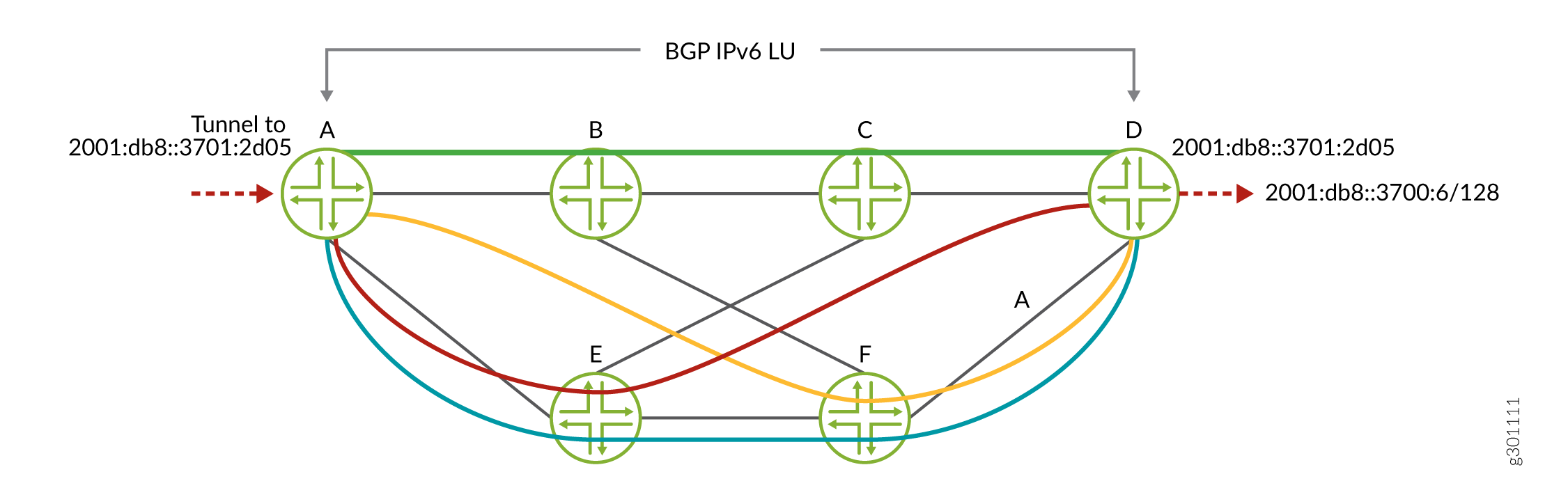
BGP-LU supports the following scenarios:
-
BGP IPv4 LU over colored BGP IPv4 SR-TE, with ISIS/OSPF IPv4 SR extensions.
-
BGP IPv4 LU over static colored and non-colored IPv4 SR-TE, with ISIS/OSPF IPv4 SR extensions.
-
BGP IPv6 LU over colored BGP IPv6 SR-TE, with ISIS IPv6 SR extensions.
-
BGP IPv6 LU over static colored and non-colored IPv6 SR-TE, with ISIS IPv6 SR extensions.
-
IPv6 Layer 3 VPN services with IPv6 local address and IPv6 neighbor address.
-
IPv6 Layer 3 VPN services over BGP IPv6 SR-TE, with ISIS IPv6 SR extensions.
-
IPv6 Layer 3 VPN services over static-colored and non-colored IPv6 SR-TE, with ISIS IPv6 SR extensions.
Supported and Unsupported Features for Color-Based Mapping of VPN Services
The following features and functionality are supported with color-based mapping of VPN services:
-
BGP Layer 2 VPN (Kompella Layer 2 VPN)
-
BGP EVPN
-
Resolution-map with a single IP-color option.
-
Colored IPv4 and IPv6 protocol next hop resolution.
-
Routing information base (also known as routing table) group based fallback to LDP LSP in inetcolor.0 routing table.
-
Colored SR-TE LSP.
-
Virtual platforms.
-
64-bit Junos OS.
-
Logical systems.
-
BGP labeled unicast.
The following features and functionality are not supported with color-based mapping of VPN services:
-
Colored MPLS LSPs, such as RSVP, LDP, BGP-LU, static.
-
Layer 2 circuit
-
FEC-129 BGP auto-discovered and LDP-signaled Layer 2 VPN.
-
VPLS
-
MVPN
-
IPv4 and IPv6 using resolution-map.
Tunnel Templates for PCE-Initiated Segment Routing LSPs
You can configure a tunnel template for PCE-initiated segment routing LSPs to pass down two additional parameters for these LSPs - Bidirectional forwarding detection (BFD) and LDP tunneling.
When a PCE-Initiated segment routing LSP is being created, the LSP is checked against policy statements (if any) and if there is a match, the policy applies the configured template for that LSP. The template configuration is inherited only if it is not provided by the LSP source (PCEP); for example, metric.
To configure a template:
-
Include the source-routing-path-template statement at the
[edit protocols source-packet-routing]hierarchy level. You can configure the additional BFD and LDP tunneling parameters here. -
Include the source-routing-path-template-map statement at the
[edit protocols source-packet-routing]hierarchy level to list the policy statements against which the PCE-initiated LSP should be checked. -
Define a policy to list the LSPs on which the template should be applied.
The
fromstatement can include either the LSP name or LSP regular expression using thelspandlsp-regexmatch conditions. These options are mutually exclusive, so you can specify only one option at a given point in time.The
thenstatement must include thesr-te-templateoption with an accept action. This applies the template to the PCE-initiated LSP.
Take the following into consideration when configuring a template for PCE-initiated LSPs:
-
Template configuration is not applicable to staticalyy configured segment routing LSPs, or any other client’s segment routing LSP.
-
PCEP-provided configuration has precedence over template configuration.
-
PCEP LSP does not inherit template segment-list configuration.
Example: Configuring Static Segment Routing Label Switched Path
This example shows how to configure static segment routing label switched paths (LSPs) in MPLS networks. This configuration helps to bring higher scalability to MPLS networks.
Requirements
This example uses the following hardware and software components:
-
Seven MX Series 5G Universal Routing Platforms
-
Junos OS Release 18.1 or later running on all the routers
Before you begin, be sure you configure the device interfaces.
Overview
Junos OS a set of explicit segment routing paths are configured on the ingress router
of a non-colored static segment routing tunnel by configuring the
segment-list
statement at the [edit protocols source-packet-routing] hierarchy
level. You can configure segment routing tunnel by configuring the
source-routing-path statement at [edit protocols
source-packet-routing] hierarchy level. The segment routing tunnel has
a destination address and one or more primary paths and optionally secondary paths
that refer to the segment list. Each segment list consists of a sequence of hops.
For non-colored static segment routing tunnel, the first hop of the segment list
specifies an immediate next hop IP address and the second to Nth hop specifies the
segment identifies (SID) labels corresponding to the link or node which the path
traverses. The route to the destination of the segment routing tunnel is installed
in inet.3 table.
Topology
In this example, configure layer 3 VPN on the provider edge routers PE1 and PE5. Configure the MPLS protocol on all the routers. The segment routing tunnel is configured from router PE1 to router PE5 with a primary path configured on router PE1 and router PE5 . Router PE1 is also configured with secondary path for path protection. The transit routers PE2 to PE4 are configured with adjacency SID labels with label pop and an outgoing interface.
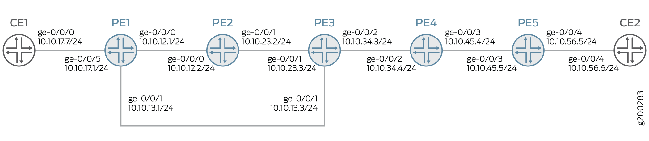
Configuration
CLI Quick Configuration
To quickly configure this example, copy the following commands, paste them into a
text file, remove any line breaks, change any details necessary to match your
network configuration, copy and paste the commands into the CLI at the
[edit] hierarchy level, and then enter
commit from configuration mode.
PE1
set interfaces ge-0/0/0 unit 0 family inet address 10.10.12.1/24 set interfaces ge-0/0/0 unit 0 family mpls maximum-labels 5 set interfaces ge-0/0/1 unit 0 family inet address 10.10.13.1/24 set interfaces ge-0/0/1 unit 0 family mpls maximum-labels 5 set interfaces ge-0/0/5 unit 0 family inet address 10.10.17.1/24 set routing-options autonomous-system 65000 set routing-options forwarding-table export load-balance-policy set routing-options forwarding-table chained-composite-next-hop ingress l3vpn set protocols mpls interface ge-0/0/0.0 set protocols mpls interface ge-0/0/1.0 set protocols mpls label-range static-label-range 1000000 1000999 set protocols bgp group pe type internal set protocols bgp group pe local-address 192.168.147.211 set protocols bgp group pe family inet-vpn unicast set protocols bgp group pe neighbor 192.168.146.181 set protocols ospf area 0.0.0.0 interface ge-0/0/0.0 set protocols ospf area 0.0.0.0 interface lo0.0 set protocols ospf area 0.0.0.0 interface ge-0/0/1.0 set protocols source-packet-routing segment-list sl-15-primary hop-1 ip-address 10.10.13.3 set protocols source-packet-routing segment-list sl-15-primary hop-2 label 1000134 set protocols source-packet-routing segment-list sl-15-primary hop-3 label 1000145 set protocols source-packet-routing segment-list sl-15-backup hop-1 ip-address 10.10.12.2 set protocols source-packet-routing segment-list sl-15-backup hop-2 label 1000123 set protocols source-packet-routing segment-list sl-15-backup hop-3 label 1000134 set protocols source-packet-routing segment-list sl-15-backup hop-4 label 1000145 set protocols source-packet-routing source-routing-path lsp-15 to 192.168.146.181 set protocols source-packet-routing source-routing-path lsp-15 binding-sid 1000999 set protocols source-packet-routing source-routing-path lsp-15 primary sl-15-primary set protocols source-packet-routing source-routing-path lsp-15 secondary sl-15-backup set policy-options policy-statement VPN-A-export term a from protocol ospf set policy-options policy-statement VPN-A-export term a from protocol direct set policy-options policy-statement VPN-A-export term a then community add VPN-A set policy-options policy-statement VPN-A-export term a then accept set policy-options policy-statement VPN-A-export term b then reject set policy-options policy-statement VPN-A-import term a from protocol bgp set policy-options policy-statement VPN-A-import term a from community VPN-A set policy-options policy-statement VPN-A-import term a then accept set policy-options policy-statement VPN-A-import term b then reject set policy-options policy-statement bgp-to-ospf from protocol bgp set policy-options policy-statement bgp-to-ospf from route-filter 10.10.0.0/16 orlonger set policy-options policy-statement bgp-to-ospf then accept set policy-options policy-statement load-balance-policy then load-balance per-packet set policy-options community VPN-A members target:65000:1 set routing-instances VRF1 instance-type vrf set routing-instances VRF1 interface ge-0/0/5.0 set routing-instances VRF1 route-distinguisher 192.168.147.211:1 set routing-instances VRF1 vrf-import VPN-A-import set routing-instances VRF1 vrf-export VPN-A-export set routing-instances VRF1 vrf-table-label set routing-instances VRF1 protocols ospf export bgp-to-ospf set routing-instances VRF1 protocols ospf area 0.0.0.0 interface ge-0/0/5.0
PE2
set interfaces ge-0/0/0 unit 0 family inet address 10.10.12.2/24 set interfaces ge-0/0/0 unit 0 family mpls set interfaces ge-0/0/1 unit 0 family inet address 10.10.23.2/24 set interfaces ge-0/0/1 unit 0 family mpls set protocols mpls static-label-switched-path adj-23 segment 1000123 set protocols mpls static-label-switched-path adj-23 segment next-hop 10.10.23.3 set protocols mpls static-label-switched-path adj-23 segment pop set protocols mpls static-label-switched-path adj-21 segment 1000221 set protocols mpls static-label-switched-path adj-21 segment next-hop 10.10.12.1 set protocols mpls static-label-switched-path adj-21 segment pop set protocols mpls interface ge-0/0/0.0 set protocols mpls interface ge-0/0/1.0 set protocols mpls label-range static-label-range 1000000 1000999 set protocols ospf area 0.0.0.0 interface ge-0/0/0.0 set protocols ospf area 0.0.0.0 interface ge-0/0/1.0
PE3
set interfaces ge-0/0/0 unit 0 family inet address 10.10.13.3/24 set interfaces ge-0/0/0 unit 0 family mpls set interfaces ge-0/0/1 unit 0 family inet address 10.10.23.3/24 set interfaces ge-0/0/1 unit 0 family mpls set interfaces ge-0/0/2 unit 0 family inet address 10.10.34.3/24 set interfaces ge-0/0/2 unit 0 family mpls set protocols mpls static-label-switched-path adj-34 segment 1000134 set protocols mpls static-label-switched-path adj-34 segment next-hop 10.10.34.4 set protocols mpls static-label-switched-path adj-34 segment pop set protocols mpls static-label-switched-path adj-32 segment 1000232 set protocols mpls static-label-switched-path adj-32 segment next-hop 10.10.23.2 set protocols mpls static-label-switched-path adj-32 segment pop set protocols mpls interface ge-0/0/1.0 set protocols mpls interface ge-0/0/2.0 set protocols mpls label-range static-label-range 1000000 1000999 set protocols ospf area 0.0.0.0 interface ge-0/0/1.0 set protocols ospf area 0.0.0.0 interface ge-0/0/2.0 set protocols ospf area 0.0.0.0 interface ge-0/0/0.0
PE4
set interfaces ge-0/0/2 unit 0 family inet address 10.10.34.4/24 set interfaces ge-0/0/2 unit 0 family mpls set interfaces ge-0/0/3 unit 0 family inet address 10.10.45.4/24 set interfaces ge-0/0/3 unit 0 family mpls set protocols mpls static-label-switched-path adj-45 segment 1000145 set protocols mpls static-label-switched-path adj-45 segment next-hop 10.10.45.5 set protocols mpls static-label-switched-path adj-45 segment pop set protocols mpls static-label-switched-path adj-43 segment 1000243 set protocols mpls static-label-switched-path adj-43 segment next-hop 10.10.34.3 set protocols mpls static-label-switched-path adj-43 segment pop set protocols mpls interface ge-0/0/2.0 set protocols mpls interface ge-0/0/3.0 set protocols mpls label-range static-label-range 1000000 1000999 set protocols ospf area 0.0.0.0 interface ge-0/0/2.0 set protocols ospf area 0.0.0.0 interface ge-0/0/3.0
PE5
set interfaces ge-0/0/3 unit 0 family inet address 10.10.45.5/24 set interfaces ge-0/0/3 unit 0 family mpls maximum-labels 5 set interfaces ge-0/0/4 unit 0 family inet address 10.10.56.5/24 set routing-options autonomous-system 65000 set protocols mpls interface ge-0/0/3.0 set protocols mpls label-range static-label-range 1000000 1000999 set protocols bgp group pe type internal set protocols bgp group pe local-address 192.168.146.181 set protocols bgp group pe family inet-vpn unicast set protocols bgp group pe neighbor 192.168.147.211 set protocols ospf area 0.0.0.0 interface ge-0/0/3.0 set protocols ospf area 0.0.0.0 interface lo0.0 set protocols bfd sbfd local-discriminator 0.0.0.32 minimum-receive-interval 1000 set protocols source-packet-routing segment-list sl-51 hop-1 ip-address 10.10.45.4 set protocols source-packet-routing segment-list sl-51 hop-2 label 1000243 set protocols source-packet-routing segment-list sl-51 hop-3 label 1000232 set protocols source-packet-routing segment-list sl-51 hop-4 label 1000221 set protocols source-packet-routing source-routing-path lsp-51 to 192.168.147.211 set protocols source-packet-routing source-routing-path lsp-51 primary sl-51 set policy-options policy-statement VPN-A-export term a from protocol ospf set policy-options policy-statement VPN-A-export term a from protocol direct set policy-options policy-statement VPN-A-export term a then community add VPN-A set policy-options policy-statement VPN-A-export term a then accept set policy-options policy-statement VPN-A-export term b then reject set policy-options policy-statement VPN-A-import term a from protocol bgp set policy-options policy-statement VPN-A-import term a from community VPN-A set policy-options policy-statement VPN-A-import term a then accept set policy-options policy-statement VPN-A-import term b then reject set policy-options policy-statement bgp-to-ospf from protocol bgp set policy-options policy-statement bgp-to-ospf from route-filter 10.10.0.0/16 orlonger set policy-options policy-statement bgp-to-ospf then accept set policy-options community VPN-A members target:65000:1 set routing-instances VRF1 instance-type vrf set routing-instances VRF1 interface ge-0/0/4.0 set routing-instances VRF1 route-distinguisher 192.168.146.181:1 set routing-instances VRF1 vrf-import VPN-A-import set routing-instances VRF1 vrf-export VPN-A-export set routing-instances VRF1 vrf-table-label set routing-instances VRF1 protocols ospf export bgp-to-ospf set routing-instances VRF1 protocols ospf area 0.0.0.0 interface ge-0/0/4.0
CE1
set interfaces ge-0/0/0 unit 0 family inet address 10.10.17.7/24 set protocols ospf area 0.0.0.0 interface ge-0/0/0.0
CE2
set interfaces ge-0/0/4 unit 0 family inet address 10.10.56.6/24 set protocols ospf area 0.0.0.0 interface ge-0/0/4.0
Configuring Device PE1
Step-by-Step Procedure
The following example requires that you navigate various levels in the configuration hierarchy. For information about navigating the CLI, see Using the CLI Editor in Configuration Mode in the CLI User Guide.
To configure Device PE1:
-
Configure the interfaces.
[edit interfaces] set ge-0/0/0 unit 0 family inet address 10.10.12.1/24 set ge-0/0/0 unit 0 family mpls maximum-labels 5 set ge-0/0/1 unit 0 family inet address 10.10.13.1/24 set ge-0/0/1 unit 0 family mpls maximum-labels 5 set ge-0/0/5 unit 0 family inet address 10.10.17.1/24
-
Configure autonomous system number and options to control packet forwarding routing options.
[edit routing-options] set autonomous-system 65000 set forwarding-table export load-balance-policy set forwarding-table chained-composite-next-hop ingress l3vpn
-
Configure the interfaces with the MPLS protocol and configure the MPLS label range.
[edit protocols mpls] set interface ge-0/0/0.0 set interface ge-0/0/1.0 set label-range static-label-range 1000000 1000999
-
Configure the type of peer group, local address, protocol family for NLRIs in updates, and IP address of a neighbor for the peer group.
[edit protocols bgp] set group pe type internal set group pe local-address 192.168.147.211 set group pe family inet-vpn unicast set group pe neighbor 192.168.146.181
-
Configure the protocol area interfaces.
[edit protocols ospf] set area 0.0.0.0 interface ge-0/0/0.0 set area 0.0.0.0 interface lo0.0 set area 0.0.0.0 interface ge-0/0/1.0
-
Configure the IPv4 address and labels of primary and secondary paths for source routing-traffic engineering (TE) policies of protocol source packet routing (SPRING).
[edit protocols source-packet-routing segment-list] set sl-15-primary hop-1 ip-address 10.10.13.3 set sl-15-primary hop-2 label 1000134 set sl-15-primary hop-3 label 1000145 set sl-15-backup hop-1 ip-address 10.10.12.2 set sl-15-backup hop-2 label 1000123 set sl-15-backup hop-3 label 1000134 set sl-15-backup hop-4 label 1000145
-
Configure destination IPv4 address, binding SID label, primary, and secondary source routing path for protocol SPRING.
[edit protocols source-packet-routing source-routing-path] set lsp-15 to 192.168.146.181 set lsp-15 binding-sid 1000999 set lsp-15 primary sl-15-primary set lsp-15 secondary sl-15-backup
-
Configure policy options.
[edit policy-options policy-statement] set VPN-A-export term a from protocol ospf set VPN-A-export term a from protocol direct set VPN-A-export term a then community add VPN-A set VPN-A-export term a then accept set VPN-A-export term b then reject set VPN-A-import term a from protocol bgp set VPN-A-import term a from community VPN-A set VPN-A-import term a then accept set VPN-A-import term b then reject set bgp-to-ospf from protocol bgp set bgp-to-ospf from route-filter 10.10.0.0/16 orlonger set bgp-to-ospf then accept set load-balance-policy then load-balance per-packet
-
Configure BGP community information.
[edit policy-options] set community VPN-A members target:65000:1
-
Configure routing instance VRF1 with instance type, interface, router distinguisher, VRF import, export and table label. Configure export policy and interface of area for protocol OSPF.
[edit routing-instances VRF1] set instance-type vrf set interface ge-0/0/5.0 set route-distinguisher 192.168.147.211:1 set vrf-import VPN-A-import set vrf-export VPN-A-export set vrf-table-label set protocols ospf export bgp-to-ospf set protocols ospf area 0.0.0.0 interface ge-0/0/5.0
Results
From configuration mode, confirm your configuration by entering the show interfaces, show policy-options, show protocols, show routing-options, and show routing-instances commands. If the output does not display the intended configuration, repeat the instructions in this example to correct the configuration.
[edit]
user@PE1# show
interfaces {
ge-0/0/0 {
unit 0 {
family inet {
address 10.10.12.1/24;
}
family mpls {
maximum-labels 5;
}
}
}
ge-0/0/1 {
unit 0 {
family inet {
address 10.10.13.1/24;
}
family mpls {
maximum-labels 5;
}
}
}
ge-0/0/5 {
unit 0 {
family inet {
address 10.10.17.1/24;
}
}
}
}
policy-options {
policy-statement VPN-A-export {
term a {
from protocol [ ospf direct ];
then {
community add VPN-A;
accept;
}
}
term b {
then reject;
}
}
policy-statement VPN-A-import {
term a {
from {
protocol bgp;
community VPN-A;
}
then accept;
}
term b {
then reject;
}
}
policy-statement bgp-to-ospf {
from {
protocol bgp;
route-filter 10.10.0.0/16 orlonger;
}
then accept;
}
policy-statement load-balance-policy {
then {
load-balance per-packet;
}
}
community VPN-A members target:65000:1;
}
routing-instances {
VRF1 {
instance-type vrf;
protocols {
ospf {
area 0.0.0.0 {
interface ge-0/0/5.0;
}
export bgp-to-ospf;
}
}
interface ge-0/0/5.0;
route-distinguisher 192.168.147.211:1;
vrf-import VPN-A-import;
vrf-export VPN-A-export;
vrf-table-label;
}
}
routing-options {
autonomous-system 65000;
forwarding-table {
export load-balance-policy;
chained-composite-next-hop {
ingress {
l3vpn;
}
}
}
}
protocols {
bgp {
group pe {
type internal;
local-address 192.168.147.211;
family inet-vpn {
unicast;
}
neighbor 192.168.146.181;
}
}
mpls {
label-range {
static-label-range 1000000 1000999;
}
interface ge-0/0/0.0;
interface ge-0/0/1.0;
}
ospf {
area 0.0.0.0 {
interface ge-0/0/0.0;
interface lo0.0;
interface ge-0/0/1.0;
}
}
source-packet-routing {
segment-list sl-15-primary {
hop-1 ip-address 10.10.13.3;
hop-2 label 1000134;
hop-3 label 1000145;
}
segment-list sl-15-backup {
hop-1 ip-address 10.10.12.2;
hop-2 label 1000123;
hop-3 label 1000134;
hop-4 label 1000145;
}
source-routing-path lsp-15 {
to 192.168.146.181;
binding-sid 1000999;
primary {
sl-15-primary;
}
secondary {
sl-15-backup;
}
}
}
}
Configuring Device PE2
Step-by-Step Procedure
The following example requires that you navigate various levels in the configuration hierarchy. For information about navigating the CLI, see Using the CLI Editor in Configuration Mode in the CLI User Guide.
-
Configure the interfaces.
[edit interfaces] set ge-0/0/0 unit 0 family inet address 10.10.12.2/24 set ge-0/0/0 unit 0 family mpls set ge-0/0/1 unit 0 family inet address 10.10.23.2/24 set ge-0/0/1 unit 0 family mpls
-
Configure the static LSP for protocol MPLS.
[edit protocols mpls static-label-switched-path] set adj-23 segment 1000123 set adj-23 segment next-hop 10.10.23.3 set adj-23 segment pop set adj-21 segment 1000221 set adj-21 segment next-hop 10.10.12.1 set adj-21 segment pop
-
Configure interfaces and static label range for protocol MPLS.
[edit protocols mpls] set interface ge-0/0/0.0 set interface ge-0/0/1.0 set label-range static-label-range 1000000 1000999
-
Configure interfaces for protocol OSPF.
[edit protocols ospf area 0.0.0.0] set interface ge-0/0/0.0 set interface ge-0/0/1.0
Results
From configuration mode on router PE2, confirm your configuration by entering the show interfaces and show protocols commands. If the output does not display the intended configuration, repeat the instructions in this example to correct the configuration.
[edit]
user@PE2# show
interfaces {
ge-0/0/0 {
unit 0 {
family inet {
address 10.10.12.2/24;
}
family mpls;
}
}
ge-0/0/1 {
unit 0 {
family inet {
address 10.10.23.2/24;
}
family mpls;
}
}
}
protocols {
mpls {
label-range {
static-label-range 1000000 1000999;
}
interface ge-0/0/0.0;
interface ge-0/0/1.0;
static-label-switched-path adj-23 {
segment {
1000123;
next-hop 10.10.23.3;
pop;
}
}
static-label-switched-path adj-21 {
segment {
1000221;
next-hop 10.10.12.1;
pop;
}
}
}
ospf {
area 0.0.0.0 {
interface ge-0/0/0.0;
interface ge-0/0/1.0;
}
}
}Verification
Confirm that the configuration is working properly.
- Verifying Route Entry of Routing Table inet.3 of Router PE1
- Verifying Route Table Entries of Routing Table mpls.0 of Router PE1
- Verifying SPRING Traffic Engineered LSP of Router PE1
- Verifying SPRING Traffic Engineered LSPs on the Ingress Router of Router PE1
- Verifying the Routing Table Entries of Routing Table mpls.0 of Router PE2
- Verifying the Status of Static MPLS LSP Segments of Router PE2
Verifying Route Entry of Routing Table inet.3 of Router PE1
Purpose
Verify the route entry of routing table inet.3 of router PE1.
Action
From operational mode, enter the show route table inet.3
command.
user@PE1> show route table inet.3
inet.3: 1 destinations, 1 routes (1 active, 0 holddown, 0 hidden)
+ = Active Route, - = Last Active, * = Both
192.168.146.181/32 *[SPRING-TE/8] 03:09:26, metric 1
> to 10.10.13.3 via ge-0/0/1.0, Push 1000145, Push 1000134(top)
to 10.10.12.2 via ge-0/0/0.0, Push 1000145, Push 1000134, Push 1000123(top)Meaning
The output displays the ingress routes of segment routing tunnels.
Verifying Route Table Entries of Routing Table mpls.0 of Router PE1
Purpose
Verify the route entries of routing table mpls.0
Action
From operational mode, enter the show route table mpls.0
command.
user@PE1> show route table mpls.0
mpls.0: 6 destinations, 6 routes (6 active, 0 holddown, 0 hidden)
+ = Active Route, - = Last Active, * = Both
0 *[MPLS/0] 03:25:52, metric 1
Receive
1 *[MPLS/0] 03:25:52, metric 1
Receive
2 *[MPLS/0] 03:25:52, metric 1
Receive
13 *[MPLS/0] 03:25:52, metric 1
Receive
16 *[VPN/0] 03:25:52
> via lsi.0 (VRF1), Pop
1000999 *[SPRING-TE/8] 03:04:03, metric 1
> to 10.10.13.3 via ge-0/0/1.0, Swap 1000145, Push 1000134(top)
to 10.10.12.2 via ge-0/0/0.0, Swap 1000145, Push 1000134, Push 1000123(top)
Meaning
The output displays the SID labels of segment routing tunnels.
Verifying SPRING Traffic Engineered LSP of Router PE1
Purpose
Verify SPRING traffic engineered LSPs on the ingress routers.
Action
From operational mode, enter the show spring-traffic-engineering
overview command.
user@PE1> show spring-traffic-engineering overview
Overview of SPRING-TE:
Route preference: 8
Number of LSPs: 1 (Up: 1, Down: 0)
External controllers:
< Not configured >
Meaning
The output displays the overview of SPRING traffic engineered LSPs on the ingress router.
Verifying SPRING Traffic Engineered LSPs on the Ingress Router of Router PE1
Purpose
Verify SPRING traffic engineered LSPs on the ingress router.
Action
From operational mode, enter the show spring-traffic-engineering lsp
detail command.
user@PE1# show spring-traffic-engineering lsp detail
Name: lsp-15
To: 192.168.146.181
State: Up
Path: sl-15-primary
Outgoing interface: ge-0/0/1.0
BFD status: N/A (Up: 0, Down: 0)
SR-ERO hop count: 3
Hop 1 (Strict):
NAI: IPv4 Adjacency ID, 0.0.0.0 -> 10.10.13.3
SID type: None
Hop 2 (Strict):
NAI: None
SID type: 20-bit label, Value: 1000134
Hop 3 (Strict):
NAI: None
SID type: 20-bit label, Value: 1000145
Path: sl-15-backup
Outgoing interface: ge-0/0/0.0
BFD status: N/A (Up: 0, Down: 0)
SR-ERO hop count: 4
Hop 1 (Strict):
NAI: IPv4 Adjacency ID, 0.0.0.0 -> 10.10.12.2
SID type: None
Hop 2 (Strict):
NAI: None
SID type: 20-bit label, Value: 1000123
Hop 3 (Strict):
NAI: None
SID type: 20-bit label, Value: 1000134
Hop 4 (Strict):
NAI: None
SID type: 20-bit label, Value: 1000145
Total displayed LSPs: 1 (Up: 1, Down: 0)Meaning
The output displays details of SPRING traffic engineered LSPs on the ingress router
Verifying the Routing Table Entries of Routing Table mpls.0 of Router PE2
Purpose
Verify the routing table entries of routing table mpls.0 of router PE2.
Action
From operational mode, enter the show route table mpls.0
command.
user@PE2> show route table mpls.0
mpls.0: 8 destinations, 8 routes (8 active, 0 holddown, 0 hidden)
+ = Active Route, - = Last Active, * = Both
0 *[MPLS/0] 03:22:29, metric 1
Receive
1 *[MPLS/0] 03:22:29, metric 1
Receive
2 *[MPLS/0] 03:22:29, metric 1
Receive
13 *[MPLS/0] 03:22:29, metric 1
Receive
1000123 *[MPLS/6] 03:22:29, metric 1
> to 10.10.23.3 via ge-0/0/1.0, Pop
1000123(S=0) *[MPLS/6] 03:22:29, metric 1
> to 10.10.23.3 via ge-0/0/1.0, Pop
1000221 *[MPLS/6] 03:22:29, metric 1
> to 10.10.12.1 via ge-0/0/0.0, Pop
1000221(S=0) *[MPLS/6] 03:22:29, metric 1
> to 10.10.12.1 via ge-0/0/0.0, PopVerifying the Status of Static MPLS LSP Segments of Router PE2
Purpose
Verify the status of MPLS LSP segments of router PE2.
Action
From operational mode, enter the show mpls static-lsp
command.
user@PE2> show mpls static-lsp
Ingress LSPs:
Total 0, displayed 0, Up 0, Down 0
Transit LSPs:
Total 0, displayed 0, Up 0, Down 0
Bypass LSPs:
Total 0, displayed 0, Up 0, Down 0
Segment LSPs:
LSPname SID-label State
adj-21 1000221 Up
adj-23 1000123 Up
Total 2, displayed 2, Up 2, Down 0Meaning
The output displays the status of static MPLS LSP segments of router PE2.
Enabling Distributed CSPF for Segment Routing LSPs
Prior to Junos OS Release 19.2R1S1, for traffic engineering of segment routing paths, you could either explicitly configure static paths, or use computed paths from an external controller. With the distributed Constrained Shortest Path First (CSPF) for segment routing LSP feature, you can compute a segment routing LSP locally on the ingress device according to the constraints you have configured. With this feature, the LSPs are optimized based on the configured constraints and metric type (traffic-engineering or IGP). The LSPs are computed to utilize the available ECMP paths to the destination with segment routing label stack compression enabled or disabled.
- Distributed CSPF Computation Constraints
- Distributed CSPF Computation Algorithm
- Distributed CSPF Computation Database
- Configuring Distributed CSPF Computation Constraints
- Distributed CSPF Computation
- Interaction Between Distributed CSPF Computation and SR-TE Features
- Distributed CSPF Computation Sample Configurations
Distributed CSPF Computation Constraints
Segment routing LSP paths are computed when all the configured constraints are met.
The distributed CSPF computation feature supports the following subset of constraints specified in the Internet draft, draft-ietf-spring-segment-routing-policy-03.txt, Segment Routing Policy for Traffic Engineering:
-
Inclusion and exclusion of administrative groups.
-
Inclusion of loose or strict hop IP addresses.
Note:You can specify only router IDs in the loose or strict hop constraints. Labels and other IP addresses cannot be specified as loose or strict hop constraints in Junos OS Release 19.2R1-S1.
-
Maximum number of segment IDs (SIDs) in the segment list.
-
Maximum number of segment lists per candidate segment routing path.
The distributed CSPF computation feature for segment routing LSPs does not support the following types of constraints and deployment scenarios:
-
IPV6 addresses.
-
Inter domain segment routing traffic engineering (SR-TE) LSPs.
-
Unnumbered interfaces.
-
Multiple protocols routing protocols such as, OSPF, ISIS, and BGP-LS, enabled at the same time.
-
Computation with prefixes or anycast addresses as destinations.
-
Including and excluding interface IP addresses as constraints.
Distributed CSPF Computation Algorithm
The distributed CSPF computation feature for segment routing LSPs uses the label stack compression algorithm with CSPF.
Label Stack Compression Enabled
A compressed label stack represents a set of paths from a source to a destination. It generally consists of node SIDs and adjacency SIDs. When label stack compression is enabled, the result of the computation is a set of paths that maximize ECMP to the destination, with minimum number of SIDs in the stack, while conforming to constraints.
Label Stack Compression Disabled
The multipath CSPF computation with label stack compression disabled finds up to N segment lists to destination, where:
-
The cost of all segment lists is equal to and the same as the shortest traffic-engineering metric to reach the destination.
-
Each segment list is comprised of adjacency SIDs.
-
The value of N is the maximum number of segment lists allowed for the candidate path by configuration.
-
No two segment lists are identical.
-
Each segment list satisfies all the configured constraints.
Distributed CSPF Computation Database
The database used for
SR-TE
computation has all links, nodes, prefixes and their characteristics irrespective of
whether traffic-engineering is enabled in those advertising nodes. In other words,
it is the union of the traffic-engineering database (TED) and the IGP link state
database of all domains that the computing node has learnt from. As a result, for
CSPF to work, you must include the igp-topology statement at the
[edit protocols isis traffic-engineering] hierarchy level.
Configuring Distributed CSPF Computation Constraints
You can use a compute profile to logically group the computation constraints. These compute profiles are referenced by the segment routing paths for computing the primary and secondary segment routing LSPs.
To configure a compute profile, include the compute-profile statement at the [edit protocols
source-packet-routing] hierarchy level.
The configuration for the supported computation constraints include:
-
Administrative groups
You can configure admin-groups under the
[edit protocols mpls]hierarchy level. Junos OS applies the administrative group configuration to the segment routing traffic-engineering (SR-TE) interfaces.To configure the computation constraints you can specify three categories for a set of administrative groups. The computation constraint configuration can be common to all candidate segment routing paths, or it can be under individual candidate paths.
-
include-any—Specifies that any link with at least one of the configured administrative groups in the list is acceptable for the path to traverse. -
include-all—Specifies that any link with all of the configured administrative groups in the list is acceptable for the path to traverse. -
exclude—Specifies that any link which does not have any of the configured administrative groups in the list is acceptable for the path to traverse.
-
-
Explicit path
You can specify a series of router IDs in the compute profile as a constraint for computing the SR-TE candidate paths. Each hop has to be an IPv4 address and can be of type strict or loose. If the type of a hop is not configured, strict is used. You must include the
computeoption under the segment-list statement when specifying the explicit path constraint. -
Maximum number of segment lists (ECMP paths)
You can associate a candidate path with a number of dynamic segment-lists. The paths are ECMP paths, where each segment-list translates into a next hop gateway with active weight. These paths are a result of path computation with or without compression.
You can configure this attribute using the
maximum-computed-segment-lists maximum-computed-segment-listsoption under the compute-profile configuration statement. This configuration determines the maximum number of such segment lists computed for a given primary and secondary LSP. -
Maximum segment list depth
The maximum segment list depth computation parameter ensures that amongst the ECMP paths that satisfy all other constraints such as administrative group, only the paths that have segment lists less than or equal to the maximum segment list depth are used. When you configure this parameter as a constraint under the compute-profile, it overrides the
maximum-segment-list-depthconfiguration under the[edit protocols source-packet-routing]hierarchy level, if present.You can configure this attribute using the
maximum-segment-list-depth maximum-segment-list-depthoption under the compute-profile configuration statement. -
Protected or unprotected adjacency SIDs
You can configure protected or unprotected adjacency SID as a constraint under the compute-profile to avoid links with the specified SID type.
-
Metric type
You can specify the type of metric on the link to be used for computation. By default, SR-TE LSPs use traffic-engineering metrics of the links for computation. The traffic-engineering metric for links is advertised by traffic-engineering extensions of IGP protocols. However, you may also choose to use the IGP-metric for computation by using the metric-type configuration in the compute profile.
You can configure this attribute using the
metric-type (igp | te)option under the compute-profile configuration statement.
Distributed CSPF Computation
The SR-TE candidate paths are computed locally such that they satisfy the configured constraints. When label stack compression is disabled, the multi-path CSPF computation result is a set of adjacency SID stacks. When label stack compression is enabled, the result is a set of compressed label stacks (composed of adjacent SIDs and node SIDs).
When secondary paths are computed, the links, nodes and SRLGs taken by the primary paths are not avoided for computation. For more information on primary and secondary paths, see Configuring Primary and Secondary LSPs.
For any LSPs with unsuccessful computation result, the computation is retried as traffic-engineering database (TED) changes.
Interaction Between Distributed CSPF Computation and SR-TE Features
- Weights Associated With Paths of an SR-TE Policy
- BFD Liveliness Detection
- inherit-label-nexthops
- Auto-Translate Feature
Weights Associated With Paths of an SR-TE Policy
You can configure weights against computed and static SR-TE paths, which contribute to the next hops of the route. However, a single path that has computation enabled can result in multiple segment lists. These computed segment lists are treated as ECMP amongst themselves. You can assign hierarchical ECMP weights to these segments, considering the weights assigned to each of the configured primaries.
BFD Liveliness Detection
You can configure BFD liveliness detection for the computed primary or secondary paths. Every computed primary or secondary path can result in multiple segment lists, as a result, the BFD parameters configured against the segment lists are applied to all the computed segment lists. If all the active primary paths go down, the pre-programmed secondary path (if provided) becomes active.
inherit-label-nexthops
You are not required to explicitly enable the
inherit-label-nexthops configuration under the
[edit protocols
                                source-packet-routing segment-list
                                    segment-list-name]
hierarchy for the computed
primary or secondary paths, as it is a default behavior.
Auto-Translate Feature
You can configure the auto-translate feature on the segment lists, and the primary or secondary paths with the auto-translate feature reference these segment lists. On the other hand, the primary or secondary on which compute feature is enabled cannot reference any segment list. As a result, you cannot enable both the compute feature and the auto-translate feature for a given primary or secondary path. However, you could have an LSP configured with a primary path with compute type and another with auto-translate type.
Distributed CSPF Computation Sample Configurations
Example 1
In Example 1,
-
The non-computed primary path references a configured segment-list. In this example, the configured segment list static_sl1 is referenced, and it also serves as the name for this primary path.
-
A computed primary should have a name configured, and this name should not reference any configured segment list. In this example, compute_segment1 is not a configured segment list.
-
The compute_profile_red compute-profile is applied to the primary path with the name compute_segment1.
-
The compute_profile_red compute-profile includes a segment list of type
compute, which is used to specify the explicit path constraint for the computation.
[edit protocols
                                source-packet-routing]
segment-list static_sl1{
hop1 label 80000
}
segment-list exp_path1 {
hop1 ip-address 10.1.1.1 loose
hop2 ip-address 10.2.2.2
compute
}
compute-profile compute_profile_red {
include-any red
segment-list exp_path1
maximum-segment-list-depth 5
}
The weights for computed path next-hops and static next-hops are 2 and 3, respectively. Assuming the next-hops for computed paths are comp_nh1, comp_nh2, and comp_nh3, and the next-hop for static path is static_nh, the weights are applied as follows:
|
Next-Hop |
Weight |
|---|---|
|
comp_nh1 |
2 |
|
comp_nh2 |
2 |
|
comp_nh3 |
2 |
|
static_nh |
9 |
Example 2
In Example 2, both the primary and secondary paths can be of compute type and can have their own compute-profiles.
[edit
                            protocols source-packet-routing]
compute-profile compute_profile_green{
include-any green
maximum-segment-list-depth 5
}
compute-profile compute_profile_red{
include-any red
maximum-segment-list-depth 8
}
Example 3
In Example 3, when compute is mentioned under a primary or secondary path, it results in local computation of a path to the destination without any constraints or other parameters for the computation.
[edit
                            protocols source-packet-routing]
source-routing-path srte_colored_policy1 {
to 10.5.5.5
color 5
binding-sid 10001
primary {
compute_segment1 {
compute
}
}
}
Example: Configuring CoS-Based Forwarding and Policy-Based Routing For SR-TE LSPs
SUMMARY CoS-based forwarding (CBF) and policy-based routing (PBR, also known as filter-based forwarding) can be enabled for non-colored segment routing-traffic engineered (SR–TE) LSPs to steer selective traffic over an explicit SR-TE path, providing you the benefit of servicing traffic based on class-of-service or a policy.
- CoS-Based Forwarding and Policy-Based Routing For SR-TE LSPs Overview
- Configure CoS-Based Forwarding and Policy-Based Routing for SR-TE LSPs
CoS-Based Forwarding and Policy-Based Routing For SR-TE LSPs Overview
- Benefits of CoS-Based Forwarding (CBF) and Policy-Based Routing (PBR) For SR-TE LSPs
- Segment Routing Path Sources Supporting CBF and PBR
- Considerations for Configuring CBF and PBR for SR-TE LSPs
Benefits of CoS-Based Forwarding (CBF) and Policy-Based Routing (PBR) For SR-TE LSPs
With CBF and PBR you can:
Use combinations of segment routing-traffic engineering (SR-TE) paths to steer service traffic in the core.
Choose the supporting services to resolve over the selected SR-TE paths.
Segment Routing Path Sources Supporting CBF and PBR
The following segment routing path sources support CoS-based forwarding and policy-based routing:
Static SR–TE paths—Statically configured source-routing paths that have the entire label stack statically configured.
PCEP—Dynamically provisioning source-routing paths created on a controller, and downloaded to an ingress router in an ERO either through PCEP segment routing extensions, or in a BGP segment routing policy through BGP segment routing extensions.
Dynamic LSPs—Dynamically created tunnels triggered through the Dynamic Tunnel Module that have last-hop ERO resolution.
Auto-translated paths—Statically configured source-routing paths that are automatically translated.
Considerations for Configuring CBF and PBR for SR-TE LSPs
Remember:
CBF and PBR is enabled only on non-colored SR-TE LSPs that are either statically or dynamically configured.
Both CBF and PBR configurations for SR-TE LSPs can co-exist on a device; the order of configuration decides the type in which the routes are forwarded.
For PBR, if the first-hop of the SR-TE LSP is a label, then you must include the
resolution preserve-nexthop-hiearchystatement at the[edit routing-options]hierarchy level.The class-based forwarding of routes for CBF is visible only in the forwarding table and not on the routes.
The policy-based forwarding of routes for PBR is done on the routes and is seen in the
show routecommand output.
Configure CoS-Based Forwarding and Policy-Based Routing for SR-TE LSPs
SUMMARY CoS-based forwarding (CBF) and policy-based routing (PBR, also known as filter-based forwarding FBF) can be used to steer selective traffic using an explicit segment routing-traffic engineered (SR-TE) label-swtiched path (LSP). Only non-colored segment routing LSPs that have the next hop configured as first hop label or IP address support CBF and PBR .
Before You Begin
You must be running Junos OS Release 20.1 and later releases to enable CBF and PBR for non-colored SR-TE LSPs.
Configure the device interfaces and ensure the devices are connected to the network.
Define segment lists and configure SR-TE LSPs and their associated parameters.
To configure an SR-TE LSP, do the following:
You can now configure CBF and PBR for the configured SR-TE LSPs.
To configure CBF, do the following
Define Differentiated Services Code Point (DSCP) classifiers to handle incoming IPv4 packets, forwarding classes, and option values.
[edit class-of-service] user@host# set classifiers dscpclassifier-name forwarding-class forwarding-class-name loss-priority level code-points [ aliases ] [ 6 bit-patterns ]
For example:
[edit class-of-service] user@host# set classifiers dscp mydscp forwarding-class af11 loss-priority low code-points 001010 user@host# set classifiers dscp mydscp forwarding-class af11 loss-priority medium-high code-points 001100 user@host# set classifiers dscp mydscp forwarding-class af11 loss-priority high code-points 001110 user@host# set classifiers dscp mydscp forwarding-class af21 loss-priority low code-points 010010 user@host# set classifiers dscp mydscp forwarding-class af21 loss-priority medium-high code-points 010100 user@host# set classifiers dscp mydscp forwarding-class af21 loss-priority high code-points 010110 user@host# set classifiers dscp mydscp forwarding-class af31 loss-priority low code-points 011010 user@host# set classifiers dscp mydscp forwarding-class af31 loss-priority medium-high code-points 011100 user@host# set classifiers dscp mydscp forwarding-class af31 loss-priority high code-points 011110 user@host# set classifiers dscp mydscp forwarding-class af41 loss-priority low code-points 100010 user@host# set classifiers dscp mydscp forwarding-class af41 loss-priority medium-high code-points 100100 user@host# set classifiers dscp mydscp forwarding-class af41 loss-priority high code-points 100110
Define forwarding classes (FCs) for grouping packets for transmission, and assign packets to output queues.
[edit class-of-service] user@host# set forwarding-classes queue queue-numner class-name
For example:
[edit class-of-service] user@host# set forwarding-classes queue 0 af11 user@host# set forwarding-classes queue 1 af21 user@host# set forwarding-classes queue 2 af31 user@host# set forwarding-classes queue 3 af41
Assign the configured classifiers to the device interfaces.
[edit class-of-service] user@host# set interfaces interface-name unit unit classifiers dscp classifier-name
For example:
[edit class-of-service] user@host# set interfaces ge-0/0/8 unit 1 classifiers dscp mydscp user@host# set interfaces ge-0/0/8 unit 2 classifiers dscp mydscp
Define CoS-based forwarding policy options with LSP next-hop as the SR-TE LSP.
[edit class-of-service] user@host# set forwarding-policy next-hop-map map-name forwarding-classes class-name lsp-next-hop source-routing-path-name
For example:
[edit class-of-service] user@host# set forwarding-policy next-hop-map my_cbf forwarding-class af11 lsp-next-hop srtelsp1 user@host# set forwarding-policy next-hop-map my_cbf forwarding-class af21 lsp-next-hop srtelsp2 user@host# set forwarding-policy next-hop-map my_cbf forwarding-class af41 lsp-next-hop srtelsp3 user@host# set forwarding-policy next-hop-map my_cbf forwarding-class af31 lsp-next-hop srtelsp4
Discard traffic that does not meet any forwarding class in the next-hop map.
[edit class-of-service] user@host# set forwarding-policy next-hop-map map-name forwarding-class-default discard
For example:
[edit class-of-service] user@host# set forwarding-policy next-hop-map my_cbf forwarding-class-default discard
Configure a policy statement that specifies that routes matching the route filter are subject to the CoS next-hop mapping specified by map-name.
[edit policy-options] user@host# set policy-statement policy-name from route-filter destination-prefix match-type <actions> user@host# set policy-statement policy-name then cos-next-hop-map map-name
For example:
[edit policy-options] user@host# set policy-statement cbf from route-filter 4.0.0.1/16 orlonger user@host# set policy-statement cbf then cos-next-hop-map my_cbf
Apply the policy to routes being exported from the routing table into the forwarding table. This enables CBF for SR-TE LSPs.
[edit routing-options] user@host# set forwarding-table export policy-name
For example:
[edit routing-options] user@host# set forwarding-table export cbf
Commit the configuration.
user@host# commit
Verify CBF Configuration
You can verify the CBF configuration using the show route
forwarding-table destination ip-address vpn vpn-name extensive command.
user@host> show route forwarding-table destination 4.0.0.1 vpn vpn1 extensive Routing table: vpn1.inet [Index 8] Internet: Destination: 4.0.0.1/32 Route type: user Route reference: 0 Multicast RPF nh index: 0 P2mpidx: 0 Flags: sent to PFE Next-hop type: indirect Next-hop type: indexed Route type: idx:0 Nexthop: 11.1.1.2 Next-hop type: Push 296, Push 801007, Push 801003, Push 801002(top) Index: 807 Reference: 1 Route interface-index: 0 Index: 1048579 Reference: 10001 Index: 837 Reference: 2 Load Balance Label: None Next-hop interface: ge-0/0/1.1 Route type: idx:1 Nexthop: 11.11.1.2 Next-hop type: Push 296, Push 801007, Push 801003, Push 801002(top) Index: 809
For CBF, the class-based forwarding of routes is visible only
in the forwarding table, unlike PBR, where the filtered routes are
visible in the show route command output.
To configure PBR, do the following
Configure a policy statement which specifies that routes matching the protocol and route filter are subject to the LSP next-hop, or are load balanced as equal-cost multipath (ECMP) in the forwarding table.
[edit policy-options] user@host# set policy-statement policy-name from protocol protocol-name user@host# set policy-statement policy-name from route-filter destination-prefix match-type <actions> user@host# set policy-statement policy-name then install-nexthop lsp lsp-name user@host# set policy-statement policy-name then load-balance per-packet
For example:
[edit policy-options] user@host# set policy-statement pbr term 1 from protocol bgp user@host# set policy-statement pbr term 1 from route-filter 4.0.0.1/32 exact user@host# set policy-statement pbr term 1 then install-nexthop lsp srtelsp1 user@host# set policy-statement pbr term 1 then load-balance per-packet user@host# set policy-statement pbr term 1 then reject
Configure the device to perform custom route resolution on protocol next hops of routes.
Note:The
resolution preserve-nexthop-hierarchystatement is mandatory for PBR to work when the first-hop of the SR-TE LSP is a label.[edit routing-options] user@host# set resolution preserve-nexthop-hierarchy
Apply the policy to routes being exported from the routing table into the forwarding table. This enables PBR for SR-TE LSPs.
[edit routing-options] user@host# set forwarding-table export policy-name
For example:
[edit routing-options] user@host# set forwarding-table export pbr
Commit the configuration.
user@host# commit
Verify PBR Configuration
You can verify the PBR configuration using the show route destination-prefix command.
user@host> show route 4.0.0.1
vpn1.inet.0: 10003 destinations, 10003 routes (10003 active, 0 holddown, 0 hidden)
+ = Active Route, - = Last Active, * = Both
4.0.0.1/32 *[BGP/170] 00:24:12, localpref 100, from 7.7.7.7
AS path: 10 I, validation-state: unverified
to 11.1.1.2 via ge-0/0/1.1, Push 50983, Push 801007, Push 801003, Push 801002(top)
> to 11.11.1.2 via ge-0/0/1.2, Push 50983, Push 801007, Push 801003, Push 801002(top)
to 11.12.1.2 via ge-0/0/1.3, Push 50983, Push 801007, Push 801003, Push 801002(top)
to 11.13.1.2 via ge-0/0/1.4, Push 50983, Push 801007, Push 801003, Push 801002(top)
user@host> show route 4.0.0.1 expanded-nh extensive
vpn1.inet.0: 10003 destinations, 10003 routes (10003 active, 0 holddown, 0 hidden)
4.0.0.1/32 (1 entry, 1 announced)
Installed-nexthop:
Indr (0xc7aaa54) 7.7.7.7 Push 50983 Session-ID: 0x16f
Krt_inh (0xc745a84) Index:1048579 PNH: 7.7.7.7
Chain (0xc7aa798) Index:823 Push 50983
Router (0xc417034) 11.1.1.2 Push 801007, Push 801003, Push 801002(top) via ge-0/0/1.1
The output displays all next-hops for the destination prefix,
4.0.0.1. The expanded-nh extensive options displays the
filtered next-hops under the Krt_inh output field.
user@host> show route 4.0.0.2
vpn1.inet.0: 10003 destinations, 10003 routes (10003 active, 0 holddown, 0 hidden)
+ = Active Route, - = Last Active, * = Both
4.0.0.2/32 *[BGP/170] 00:30:14, localpref 100, from 7.7.7.7
AS path: 10 I, validation-state: unverified
to 11.1.1.2 via ge-0/0/1.1, Push 569, Push 801007, Push 801003, Push 801002(top)
> to 11.11.1.2 via ge-0/0/1.2, Push 569, Push 801007, Push 801003, Push 801002(top)
to 11.12.1.2 via ge-0/0/1.3, Push 569, Push 801007, Push 801003, Push 801002(top)
to 11.17.1.2 via ge-0/0/1.8, Push 569, Push 801007, Push 801003, Push 801002(top)
user@host> show route 7.7.7.7 protocol spring-te
inet.0: 10082 destinations, 10119 routes (10082 active, 0 holddown, 0 hidden)
inet.3: 25 destinations, 77 routes (25 active, 0 holddown, 0 hidden)
+ = Active Route, - = Last Active, * = Both
7.7.7.7/32 *[SPRING-TE/1] 00:00:32, metric 1, metric2 4
> to 11.1.1.2 via ge-0/0/1.1, Push 801007, Push 801003, Push 801002(top)
to 11.11.1.2 via ge-0/0/1.2, Push 801007, Push 801003, Push 801002(top)
to 11.12.1.2 via ge-0/0/1.3, Push 801007, Push 801003, Push 801002(top)
to 11.17.1.2 via ge-0/0/1.8, Push 801007, Push 801003, Push 801002(top)
For PBR the show route command output does the policy-based
filtering of routes.
Enabling Multiple Paths for SR-TE LSPs in PCEP
You can configure multiple paths (primary or secondary) for PCEP SR-TE LSPs (statically configured, delegated, and PCE-initiated) as defined in draft-ietf-pce-multipath-06. Only one secondary path configuration is supported and only for statically configured SR-TE LSPs. The PCEP extensions defined in draft-ietf-pce-multipath-06 enable PCEP to propagate multiple paths (multipath) for the LSPs between PCEP endpoints.
Benefits of multiple paths for PCEP SR-TE LSPs
-
LSPs can have multiple sets of EROs to a destination
-
Provides load balancing capabilities by configuring weights for individual EROs
-
Aligns with SR-TE architecture draft for defining candidate paths
The following PCEP multiple path capabilities are supported:
-
When PCEP for multiple paths is enabled (default), you can configure multiple primary (or one secondary) paths in a PCC configured and controlled candidate path.
-
When PCEP for multiple paths is disabled, you can configure only one primary path in a candidate path. Secondary path configuration is not allowed.
If you enable PCEP multipaths, compute-profile can now be configured with
maximum number of segment-lists (maximum-computed-segment-lists) greater
than 1.
When PCEP for multiple paths is enabled, PCCD will not send constraints for PCC controlled candidate paths.
When PCEP multipath capability is enabled, secondary path configuration is allowed for a non-delegated PCC candidate path, the EXPLICIT-ROUTE object (EROs) specific to the secondary path is sent to the PCE with backup flag set for the ERO. Primary paths do not include the MULTIPATH-BACKUP-TLV in the PCRpt message. Secondary path include MULTIPATH-BACKUP-TLV with backup flag set.
The following PCEP multipath functionalities are supported:
-
Multipath weight TLV (MULTIPATH-WEIGHT-TLV) in path attribute (PATH-ATTRIB) object
-
MULTIPATH-BACKUP TLV in path attribute (PATH-ATTRIB) object only for PCC controlled SR-TE LSPs
-
MULTIPATH-CAP TLV in PCEP LSP object
-
Restricts multiple primary and secondary paths in SR candidate path when PCEP multipath is disabled
-
Multiple primary paths and secondary paths in SR candidate path when PCEP multipath is enabled for PCC controlled LSPs
-
Maximum computed segment lists (
max-computed-segment-lists) more than 1 in SR-TE compute profile for delegated and PCE-initiated LSPs -
Multiple EROs for PCE-initiated candidate path in SR-TE and in PCCD
-
SRv6 LSPs
-
SR MPLS (IPv4)
-
SR MPLS (IPv4) dynamic tunnels
-
Multi-controller support
-
Multiple ERO paths for PCE-initiated, PCC-configured and controlled, and delegated colored and uncolored candidate paths
-
Backward compatible with earlier versions of Paragon Pathfinder. For backward compatibility, you need to configure
disable-multipath-capabilityconfiguration statement at the [edit protocols pcep] hierarchy level. -
Error code support for failure in validation of PCE-initiated candidate paths
-
Total sub-candidate paths per candidate path is limited to 127. For PCE initiated LSPs, if the number of ERO paths crosses 127, SR-TE throws ERROR to PCCD (and PCCD sends PCEP error message to PCE) and the corresponding ERO paths are rejected.
-
The following PCEP error messages are supported:
| Error type | Error value | Meaning | Usage |
|---|---|---|---|
| 19 | 20 | Backup path not supported | This occurs when MULTIPATH-BACKUP TLV is received by the PCC. |
| 24 | 1 | Unacceptable instantiation parameters | This occurs when PCE tries to add more than 127 sub-candidate paths per candidate path. |
Limitations
The following PCEP limitations apply:
-
The following TLVs mentioned in the draft-ietf-pce-multipath-06 are not supported:
-
Multipath backup TLV
-
Multipath opposite direction path TLV
-
Composite candidate path
-
-
When multipath capability is disabled in PCEP, configuring multiple sub-candidate paths is not allowed. However, on Junos devices without multipath capability (Junos OS versions earlier than 22.4R1), multiple sub-candidate path configuration is allowed. When PCEP multi-segment is enabled (by default), multiple primary paths are allowed for PCC controlled LSPs for the purpose of reporting. However, only one primary path is supported for delegated candidate path when PCEP multi-segment is enabled.
-
Admin groups and any other constraints will not be notified to PCE for PCC configured and controlled SR-MPLS and SRv6 candidate paths (with single or multiple primary configurations). There is no impact for delegated and PCE-initiated candidate paths.
-
When PCEP multipath capability is enabled, secondary path configuration is allowed for non-delegated candidate paths. When the PCEP multipath capability is disabled, secondary path configuration is not allowed.
-
Candidate paths cannot have a mix of PCE-initiated and delegated LSPs.
-
Multiple sub-candidate paths for a PCE-initiated colored candidate path is not supported.
-
Delegate features with multiple sub-candidate paths in a candidate path is not supported.
Configuration
To enable PCCD to send multipath capability TLV in LSP object to notify the maximum
computed segment list for a specific candidate path, include the
propagate-max-segmentlist configuration statement at the [edit
protocols pcep] hierarchy level. By default, the TLV is not sent in LSP object.
user@host# set protocols pcep propagate-max-computed-segmentlist;
To disable PCEP multiple capability session for all PCEs, include the
disable-multipath-capability configuration statement at the [edit
protocols pcep] hierarchy level.
user@host# set protocols pcep disable-multipath-capability;
[edit protocols]
pcep {
disable-multipath-capability;
propagate-max-segmentlist;
}
You can enable the following protocol traceoptions for diagnostics:
-
user@host# set protocols pcep traceoptions… -
user@host# set protocols pcep pce pce1 traceoptions… -
user@host# set protocols source-packet-routing traceoptions
You can use the following show commands to display the state of LSPs in PCC:
-
user@host> show path-computation-client lsp—Display the state of label-switched paths (LSPs) known to the Path Computation Client (PCC). -
user@host> show path-computation-client lsp extensive—Display extensive level of output about each known LSP - point-to-point and point-to-multipoint LSPs. -
user@host> show path-computation active-pce—Display the status of multipath in the sessions. -
user@host> show spring-traffic-engineering lsp detail—Display ingress details of SPRING traffic engineering.
Enabling Transport Layer Security for PCEP Sessions
Transport Layer Security (TLS) provides support for peer authentication, message encryption, and integrity. You can enable TLS in Path Computation Client (PCC) to establish TCP connection with the Path Computation Element (PCE) as defined in RFC 8253. This creates a secure PCEP session (PCEPS) to transport PCEP messages.
This document describes how to enable TLS for PCEP sessions to secure interactions with PCE, including initiation of the TLS procedures, the TLS handshake mechanism, the TLS methods for peer authentication. Secure transport for PCEP over TLS is also known as PCEPS.
- Benefits of Enabling TLS for PCEP Sessions
- Enabling TLS in Path Computation Client (PCC)
- Updating Certificates Using the Public Key Infrastructure (PKI)
- Establishing TLS Connection
- Understanding the Basic TLS Handshake Mechanism
- Diagnosing and Validating TLS for PCEP Sessions
- Sample Output
Benefits of Enabling TLS for PCEP Sessions
-
Protects PCEP sessions from attacks such as spoofing (PCC or PCE impersonation), snooping (message interception), falsification, and denial of service.
-
Leverages TLS security benefits.
Enabling TLS in Path Computation Client (PCC)
To enable TLS in PCC and to establish PCEPS session, set the tls-strict
CLI statement at the [edit protocols pcep] hierarchy level.
After enabling tls-strict configuration statement, the following events happen:
-
PCEP session flaps. Any existing TCP connection is terminated and a reconnection is done using TLS.
-
PCC establishes TCP connection with the PCE.
-
TLS procedures are initiated by the StartTLS message from PCE to PCC and from PCC to PCE. The StartTLS message is sent by PCC and the StartTLSWait timer is started. You can configure the StartTLSWait timer by configuring the
start-tls-wait-timer secondsCLI statement at the [edit protocols pcep pce pce-id] hierarchy level.Note:The recommended value for the StartTLSWait timer is 60 seconds and must not be less than the OpenWait timer. The default OpenWait timer value is set as 60 seconds.
-
If Open message is received by PCC instead of StartTLS message, PCErr message with Error-Type set to 1 (PCEP session establishment failure) and Error-value set to 1 (reception of an invalid Open message or a non-Open message), and the TCP session is closed.
-
If StartTLS message is not received from PCE, then after the StartTLSWait timer expires, PCC sends a PCErr message with Error-Type set to 25 (PCEP StartTLS failure) and Error-value set to 5 (no StartTLS message (nor PCErr/Open) before StartTLSWait timer expiry), and the TCP session is closed.
-
-
Negotiation and establishment of TLS connection happens.
-
Exchange of PCEP messages is started as per RFC5440.
If you do not enable the tls-strict CLI statement under the
[edit protocols pcep] hierarchy level, then while establishing a PCEP
session, if the StartTLS message is received by PCC instead of
Open message, PCErr message with
Error-Type set to 1 (PCEP session establishment failure) and Error-value set to 1
(reception of an invalid Open message or a non-Open message), then the TCP session is
closed.
To establish a successful PCEPS session, TLS must be enabled on both PCC and PCE.
Updating Certificates Using the Public Key Infrastructure (PKI)
The PKI doesn’t notify PCC about certificate expiry. You must manually update the certificate using the following CLI command. In this method, you must keep track of the certificate expiry date.
user@host> request security pki local-certificates re-enroll certificate id
Establishing TLS Connection
The following steps describes how a TLS connection (using TLS v1.2) is established:
-
Generate certificates for the nodes (Junos OS devices/pce-server). You can generate the certificates using one of the following methods:
-
Method 1—Generate key-pair and CSR on the device and send this CSR to CA to get the certificate. Once the certificate is issued, it is copied to the box and installed.
-
Method 2—Generate key-pair and the certificate out of the box. Both the certificate and the private key are copied on the device and installed together.
-
-
Load the certification authority (CA) on the PCC so that the PCE server certificate can be validated against the loaded CA.
user@host# set security pki ca-profile pccd-tls ca-identity pccd-tls user@host# commit
user@host> request security pki ca-certificate load ca-profile pccd-tls filename /var/tmp/ca.crt
Note:CAs can be loaded in flat hierarchy as an independent CA. If a CA is a sub-CA of another CA, the chain is constructed internally by PKI.
Note:The server certificate should be signed by a CA. Self-signed certificates are not allowed.
-
Enable TLS on PCC.
-
PCEP session is established over TLS with TLS handshake mechanism.
-
PCE server listens to port 4189 for incoming PCC connection requests through TLS.
-
PCC initiates the connection request to destination port 4189.
-
Upon completion of a three-way handshake, the TLS handshake begins by using the certificates and the one-way authentication is done (PCC authenticates server certificate). Both the server and client waits for StartTLSWait time to receive the StartTLS message. You can configure the StartTLSWait timer by configuring the
start-tls-wait-timer secondsCLI statement at the [edit protocols pcep pce pce-id] hierarchy level.Note:The recommended value for the StartTLSWait timer is 60 seconds and must not be less than the OpenWait timer. The default OpenWait timer value is set as 60 seconds.
-
After the successful TLS handshake session, PCC and PCE initiates PCEP session establishment over TLS during which the session parameters are negotiated.
-
If the certificate validation fails, then PCC terminates the TCP connection.
-
-
PCEP message is sent over TLS connection as application data.
-
Encryption and decryption happen on both PCC and PCE after a successful TLS handshake.
-
When the PCEP session is closed, the TLS session is removed.
If the certificate is expired, revoked, or reloaded during an ongoing PCEP over TLS session, the ongoing session is not affected.
Understanding the Basic TLS Handshake Mechanism
The handshake is a series of the messages exchanged between a server and a client. The exact steps in handshake varies depending on key exchange algorithm, cipher suite, etc. The following are the basic TLS handshake mechanism steps:
-
Client Hello—The client initiates the handshake by sending this message. This message contains TLS version, list of supported cryptographic algorithms or cipher suite and other client details.
-
Server Hello—The server replies to Client Hello by sending Sever Hello message. This message contains server certificate, selected cryptographic algorithm, session id and server’s public key.
-
Authentication—The client in background verifies the server’s certificate with configured Certificate Authority which had issued the certificate. On successful verification the client confirms that the server is genuine and continues with interacting.
-
Optional Client Certificate—If the server has requested a certificate from the client in Server Hello message, then the client sends the client certificate (only in case of mutual TLS).
-
Client Key Exchange—The client sends secret Key encrypted with the Server’s Public key (acquired in Server Hello message).
-
Decrypt secret key—The server decrypts the secret key using the Private key.
-
Client Finished—The client sends a finish message which is encrypted with the shared secret key and signals handshake complete.
-
Server Finished—The server responds with finish message which is encrypted with the shared secret key and signals handshake complete.
-
Exchange Messages—The messages after handshake completion are symmetrically encrypted.
Diagnosing and Validating TLS for PCEP Sessions
For diagnostics, use the following traceoptions CLI statements:
user@host# set protocols pcep traceoptions … user@host# set protocols pcep pce pce-id traceoptions … user@host# set protocols source-packet-routing traceoptions
Enable PKI logs using the following configuration and capture the same file from /var/log/<filename>
user@host# set security pki traceoptions file <filename> user@host# set security pki traceoptions flag all sss
Verify the loaded CA certificate using the following command:
user@host> show security pki ca-certificate detail
Sample Output
The following is a sample output of show path-computation-client
statistics command:
user@host> show path-computation-client statistics
Warning: License key missing; requires 'PCEP' license
PCE ns1
--------------------------------------------
General
PCE IP address : 192.168.18.1
Local IP address : 190.168.18.101
Priority : 0
PCE status : PCE_STATE_UP
Session type : PCE_TYPE_STATEFULACTIVE
LSP provisioning allowed : On
P2MP LSP report allowed : On
P2MP LSP update allowed : On
P2MP LSP init allowed : On
Session SRv6 Capable : No
PCE-mastership : main
PCE Traffic Steering : Off
PCC TLS Enabled : Yes
PCE TLS Enabled : Yes
Session TLS Enabled : Yes
Counters
PCReqs Total: 0 last 5min: 0 last hour: 0
PCReps Total: 0 last 5min: 0 last hour: 0
PCRpts Total: 0 last 5min: 0 last hour: 0
PCUpdates Total: 0 last 5min: 0 last hour: 0
PCCreates Total: 0 last 5min: 0 last hour: 0
Timers
Local Keepalive timer: 0 [s] Dead timer: 0 [s] LSP cleanup timer: - [s]
Remote Keepalive timer: 0 [s] Dead timer: 0 [s] LSP cleanup timer: - [s]
Errors
PCErr-recv
PCErr-sent
PCE-PCC-NTFS
PCC-PCE-NTFS
Pcupdate empty ero action counters
Send-err : 0
Tear down path : 0
Routing decision : 0
Routing decision failed: 0
This sample output provides the following information:
-
TLS is enabled at PCC.
-
PCE is TLS capable.
-
TLS session is established. This also indicates that the PCE server certificate is valid.
-
PCEPS session status is up and running.
Reporting Path Optimization and Computed Metrics in PCEP
Metric object in PCEP is used for several purposes. Metric object indicates the metric type that is used for path optimization. Metric object also indicates a bound on the path cost that must not be exceeded for the path to be considered as acceptable. Metric object also indicates the computed metric.
We support metric object for path optimization (interior gateway protocol, traffic engineering, and path delay) and reporting of computed metric for RSVP and SR-TE LSPs.
Metric object for path optimization and reporting of computed metric is not applicable for SRv6-TE LSPs.
- Benefits of Reporting Path Optimization and Computed Metrics in PCEP
- Understanding Optimization Metrics
- Configuring Optimization Metrics for LSPs
- Sample Output
Benefits of Reporting Path Optimization and Computed Metrics in PCEP
-
Reporting of path optimization metrics configured in PCC helps PCE to be aware of the constraints that is used for path computation.
-
Reporting of computed metrics to the PCE. This helps PCE to analyze if the LSP requires further optimization.
Understanding Optimization Metrics
The following section describes the intended and actual optimization metrics for RSVP and and SR-TE (SR MPLS) LSPs in PCEP.
- Locally Created RSVP LSP
- Delegated RSVP LSP
- PCE-initiated RSVP LSP
- Delegated SR-TE LSP
- PCE-initiated SR-TE LSP
- Sending Optimization Metric in PCRpt Message
- Sending Computed Metric in PCRpt Message
- Backward Incompatibility for Route Metric
Locally Created RSVP LSP
To optimize the locally created RSVP LSPs with metrics, configure the optimization metrics (IGP, TE, and path delay) so that the configured metric is reported through PCEP. The computed metric is sent as an actual metric in PCEP through the PCRpt message.
Delegated RSVP LSP
To report the optimization metrics for delegated RSVP LSPs, configure the optimization metrics (IGP, TE, and path delay).
Intended Metric:
-
When the optimization metric is configured at the time of delegation of LSP, the information is sent to PCE through PCRpt message.
-
When the optimization metric is configured after the delegation of LSP, the change is applied on the LSP/communicated to the PCE when the LSP control status becomes locally controlled.
-
When PCUpd message is received, if optimization metric is present in the message, the metric is used as intended metric in subsequent PCRpt messages till the LSP control status is externally controlled.
-
When PCUpd message is received, if optimization metric is not present in the message, subsequent PCRpt messages do not contain intended metric.
-
When the LSP control status changes to locally controlled, optimization metric configured from Junos CLI will be the intended metric in the PCRpt message.
Actual Metric:
-
While delegating the LSP, PCRpt message do not contain actual metric.
-
When PCUpd message is received, if computed metric is present in the message, the metric is used as actual metric in subsequent PCRpt messages till the LSP control status is externally controlled.
-
When PCUpd message is received, if computed metric is not present in the message, subsequent PCRpt messages do not contain actual metric.
-
When the LSP control status changes to locally controlled, metric computed by PCC is sent as actual metric in the PCRpt message.
PCE-initiated RSVP LSP
To report the optimization metrics for PCE-initiated RSVP LSPs, configure the optimization metrics (IGP, TE, and path delay) in a template. The template is then applied to the PCE-initated LSP when the LSP control status becomes locally controlled.
Intended Metric:
-
When a PCE-initiated LSP is mapped to a template with optimization metric, the configuration is applied to the LSP and sent to the PCE when the LSP control status changes to locally controlled.
-
When PCInit/PCUpd message is received, if optimization metric is present in the message, the metric is used as intended metric in subsequent PCRpt messages till the LSP control status is externally controlled.
-
When PCInit/PCUpd message is received, if optimization metric is not present in the message, subsequent PCRpt messages do not contain intended metric.
-
When the LSP control status becomes locally controlled, optimization metric present in the template is used as intended metric in the PCRpt message.
Actual Metric:
-
When PCInit/PCUpd message is received, if the computed metric is present in the message, the metric is used as actual metric in subsequent PCRpt messages till the LSP control status is externally controlled.
-
When PCInit/PCUpd message is received, if the computed metric is not present in the message, subsequent PCRpt messages do not contain actual metric.
-
When the LSP control status changes to locally controlled, metric computed by PCC is sent as actual metric in the PCRpt message.
Delegated SR-TE LSP
To report the optimization metrics for delegated SR-TE (SR MPLS) LSPs, configure the optimization metrics (IGP, TE, and path delay).
Intended Metric:
-
When the optimization metric is configured at the time of delegation of LSP, the information is sent to the PCE through the PCRpt message.
-
When the optimization metric is configured after the delegation of LSP, the change is applied on the LSP/communicated to the PCE when the LSP control status becomes locally controlled.
-
When PCUpd message is received, if optimization metric is present in the message, the metric is used as intended metric in subsequent PCRpt messages till the LSP control status is externally controlled.
-
When PCUpd message is received, if optimization metric is not present in the message, subsequent PCRpt messages do not contain intended metric.
-
When the LSP control status changes to locally controlled, optimization metric configured from Junos CLI will be the intended metric in the PCRpt message.
Actual Metric:
-
When LSP is delegated after the creation, at the time of LSP delegation if LSP has 1 ERO, computed values of IGP, TE and delay metrics are sent as actual metrics in the PCRpt message.
-
When LSP is delegated after the creation, at the time of LSP delegation if LSP has multiple EROs, computed metric/actual metric is not sent in the PCRpt message as actual metric needs to be sent per LSP (not per ERO) in PCEP.
-
When PCUpd message is received, if computed metric is present in the message, the metric is used as actual metric in subsequent PCRpt messages till the LSP control status is externally controlled.
-
When PCUpd message is received, if computed metric is not present in the message, subsequent PCRpt messages do not contain actual metric.
-
When the LSP control status changes to locally controlled, IGP, TE and delay metrics computed in PCC are sent as actual metrics in the PCRpt message.
PCE-initiated SR-TE LSP
Intended metrics or actual metric sent by PCE in PCInit/PCUpd messages are reported back to PCE through PCRpt message till the LSP is externally controlled.
Intended Metric:
-
When PCInit/PCUpd message is received, if optimization metric is present in the message, the metric is used as intended metric in subsequent PCRpt messages till the LSP control status is externally controlled.
-
When PCInit/PCUpd message is received, if optimization metric is not present in the message, subsequent PCRpt messages do not contain intended metric.
-
When the LSP control status becomes locally controlled, intended metric will not be sent.
Actual Metric:
-
When PCInit/PCUpd message is received, if computed metric is present in the message, the metric is used as actual metric in subsequent PCRpt messages till the LSP control status is externally controlled.
-
When PCInit/PCUpd message is received, if computed metric is not present in the message, subsequent PCRpt messages do not contain actual metric.
-
When the LSP control status changes to locally controlled, subsequent PCRpt messages do not contain actual metric.
Sending Optimization Metric in PCRpt Message
Optimization metric is sent to the PCE through the
intended-attributes-list in the PCRpt message. Metric value is set to 0
and B, C flags are set to 0. Metric type indicates the metric to be optimized.
Sending Computed Metric in PCRpt Message
Computed metric is sent to the PCE through the actual-attributes-list in
the PCRpt message. Metric value is the computed metric value and metric type indicates the
computed metric type. B flag is set to 0, C flag is set to 1.
Backward Incompatibility for Route Metric
As route metric is supported using vendor TLV, PCC will not process route metric sent in metric object by Juniper PCE supporting Northstar and older releases of paragon pathfinder.
Configuring Optimization Metrics for LSPs
You can configure optimization metrics (IGP, TE, and path delay) for RSVP LSPs and SR-TE LSP.
To configure the IGP, TE, and path delay optimization metrics for RSVP LSPs, include the
metric-type <igp|te|delay|delay minimum> CLI
statement at the [edit protocols mpls label-switched-path
<lsp-name>] hierarchy level.
To configure the IGP, TE, and path delay optimization metrics for SR-TE LSPs, include the
metric-type <igp|te|delay|delay minimum> CLI
statement at the [edit protocols source-packet-routing compute-profile
<compute-profile-name>] hierarchy level.
Sample Output
You can use the show path-computation-client lsp and show
path-computation-client lsp extensive CLI commands to display the state of
label-switched paths (LSPs) known to the Path Computation Client (PCC).
The following is a sample output of show path-computation-client lsp
extensive:
user@host> show path-computation-client lsp extensive name sr_lsp
LSP Name : sr_lsp
PathName : -
From : 192.168.1.101
To : 192.168.1.106
Path Setup Type : spring-te
State : Up
Active Path : Yes
Link Protection : none
LSP Type : ext-provised
P2mp tree : NULL
Path cspf status : external_cspf
Controller : ns1
Template : NULL
PLSP-ID : 31
LSP-ID : 0
RSVP Error : 0x0
Requested AutoBw : 0bps
Record Route : (Label=299792)
From PCE ERO (received) : (Label=299792)
From RPD ERO (reported) : (Label=299792)
Configured ERO on PCC : Not Supported
Bandwidth:
Intended : 98.76Kbps
Actual : 0bps
Intended Metric:
Metric type Bound Optimization
IGP 0 TRUE
Actual Metric:
Metric type Computed value
IGP 50
Route Metric : 50
Mapped Flowspec (FS-Ids) : -
LSP Attributes:
Exclude-Any: 0, Include-Any: 0, Include-All: 0
Setup Priority: 0, Hold-Priority: 0
Local Protection Bit: FALSE
Last Rpt/Pcreqest received from RPD at : 22:15:32.000
Last Update sent to PCE at : 16:00:00.000
Last PcUpdate/PcCreate received from PCE at : 22:15:32.000
Last error sent to PCE at : 16:00:00.000
Last 5 reasons to send Report/Pcrequest : , , , ,
The output shows that the LSP is optimized with the metric type IGP. The computed value of IGP metric is 50. The Route metric installed in the route table is 50.
Change History Table
Feature support is determined by the platform and release you are using. Use Feature Explorer to determine if a feature is supported on your platform.
external
cspf, two new path computation types are introduced for the PCE-controlled LSPs:
local cspf and no cspf.