ON THIS PAGE
Configuring Path Protection in an MPLS Network (CLI Procedure)
Configuring MPLS Inter-AS Link-Node Protection with Labeled BGP
Configuring Egress Protection Service Mirroring for BGP Signaled Layer 2 Services
Example: Configuring MPLS Egress Protection Service Mirroring for BGP Signaled Layer 2 Services
Example: Configuring Layer 3 VPN Egress Protection with PLR as Protector
Understanding MPLS and Path Protection on EX Series Switches
Node and Path Protection for MPLS LSPs
MPLS and Traffic Protection
Typically, when an LSP fails, the router immediately upstream from the failure signals the outage to the ingress router. The ingress router calculates a new path to the egress router, establishes the new LSP, and then directs the traffic from the failed path to the new path. This rerouting process can be time-consuming and prone to failure. For example, the outage signals to the ingress router might get lost, or the new path might take too long to come up, resulting in significant packet drops. The Junos OS provides several complementary mechanisms for protecting against LSP failures:
Standby secondary paths—You can configure primary and secondary paths. You configure secondary paths with the
standbystatement. To activate traffic protection, you need to configure these standby paths only on the ingress router. If the primary path fails, the ingress router immediately reroutes traffic from the failed path to the standby path, thereby eliminating the need to calculate a new route and signal a new path. For information about configuring standby LSPs, see Configuring Hot Standby of Secondary Paths for LSPs.Fast reroute—You configure fast reroute on an LSP to minimize the effect of a failure in the LSP. Fast reroute enables a router upstream from the failure to route around the failure quickly to the router downstream of the failure. The upstream router then signals the outage to the ingress router, thereby maintaining connectivity before a new LSP is established. For a detailed overview of fast reroute, see Fast Reroute Overview. For information about configuring fast reroute, see Configuring Fast Reroute.
Link protection—You can configure link protection to help ensure that traffic traversing a specific interface from one router to another can continue to reach its destination in the event that this interface fails. When link protection is configured for an interface and configured for an LSP that traverses this interface, a bypass LSP is created that handles this traffic if the interface fails. The bypass LSP uses a different interface and path to reach the same destination. For information about configuring link protection, see Configuring Link Protection on Interfaces Used by LSPs.
When standby secondary path, and fast reroute or link protection are configured on an LSP, full traffic protection is enabled. When a failure occurs in an LSP, the router upstream from the failure routes traffic around the failure and notifies the ingress router of the failure. This rerouting keeps the traffic flowing while waiting for the notification to be processed at the ingress router. After receiving the failure notification, the ingress router immediately reroutes the traffic from the patched primary path to the more optimal standby path.
Fast reroute and link protection provide a similar type of traffic protection. Both features provide a quick transfer service and employ a similar design. Fast reroute and link protection are both described in RFC 4090, Fast Reroute Extensions to RSVP-TE for LSP Tunnels. However, you need to configure only one or the other. Although you can configure both, there is little, if any, benefit in doing so.
Node-Link Protection Overview
Node-link protection (many-to-one or facility backup) extends the capabilities of link protection and provides slightly different protection from fast reroute. While link protection is useful for selecting an alternate path to the same router when a specific link fails, and fast reroute protects interfaces or nodes along the entire path of an LSP, node-link protection establishes a bypass path that avoids a particular node in the LSP path.
When you enable node-link protection for an LSP, you must also enable link protection on all RSVP interfaces in the path. Once enabled, the following types of bypass paths are established:
Next-hop bypass LSP—Provides an alternate route for an LSP to reach a neighboring router. This type of bypass path is established when you enable either node-link protection or link protection.
Next-next-hop bypass LSP—Provides an alternate route for an LSP through a neighboring router en route to the destination router. This type of bypass path is established exclusively when node-link protection is configured.
Figure 1 illustrates the example MPLS network topology used in this topic. The example network uses OSPF as the interior gateway protocol (IGP) and a policy to create traffic.
The MPLS network in Figure 1 illustrates a router-only network that consists of unidirectional LSPs between R1 and R5, (lsp2-r1-to-r5) and between R6 and R0 (lsp1-r6-to-r0). Both LSPs have strict paths configured that go through interface fe-0/1/0.
In the network shown in Figure 1, both types of bypass paths are preestablished around the protected node (R2). A next-hop bypass path avoids interface fe-0/1/0 by going through R7, and a next-next-hop bypass path avoids R2 altogether by going through R7 and R9 to R4. Both bypass paths are shared by all protected LSPs traversing the failed link or node (many LSPs protected by one bypass path).
Node-link protection (many-to-one or facility backup) allows a router immediately upstream from a node failure to use an alternate node to forward traffic to its downstream neighbor. This is accomplished by preestablishing a bypass path that is shared by all protected LSPs traversing the failed link.
When an outage occurs, the router immediately upstream from the outage switches protected traffic to the bypass node, and then signals the failure to the ingress router. Like fast reroute, node-link protection provides local repair, restoring connectivity faster than the ingress router can establish a standby secondary path or signal a new primary LSP.
Node-link protection is appropriate in the following situations:
Protection of the downstream link and node is required.
The number of LSPs to be protected is large.
Satisfying path selection criteria (priority, bandwidth, and link coloring) for bypass paths is less critical.
Control at the granularity of individual LSPs is not required.
Path Protection Overview
The main advantages of path protection are control over where the traffic goes after a failure and minimum packet loss when combined with fast reroute (one-to-one backup or link protection). Path protection is the configuration, within a label-switched path (LSP), of two types of paths: a primary path, used in normal operations, and a secondary path used when the primary fails, as shown in Figure 2.
In Figure 2, an MPLS network consisting of eight routers has a primary path between R1 and R5 which is protected by the secondary path between R1 and R5. When a failure is detected, such as an interface down event, an Resource Reservation Protocol (RSVP) error message is sent to the ingress router which switches traffic to the secondary path, maintaining traffic flow.
If the secondary path is pre-signaled or on standby, recovery time from a failure is faster than if the secondary path is not pre-signaled. When the secondary path is not pre-signaled a call-setup delay occurs during which the new physical path for the LSP is established, extending the recovery time. If the failure in the primary path is corrected, and after a few minutes of hold time, the ingress router switches traffic back from the secondary path to the primary path.
Because path protection is provided by the ingress router for the entire path, there can be some disadvantages, for example, double-booking of resources and unnecessary protection of links. By protecting a single resource at a time, local protection can remedy these disadvantages.
Configuring Path Protection in an MPLS Network (CLI Procedure)
The Junos OS implementation of MPLS on EX Series switches provides path protection as a mechanism for protecting against label switched path (LSP) failures. Path protection reduces the time required to recalculate a route in case of a failure within the MPLS tunnel. You configure path protection on the ingress provider edge switch in your MPLS network. You do not configure the egress provider edge switch or the provider switches for path protection. You can explicitly specify which provider switches are used for the primary and secondary paths, or you can let the software calculate the paths automatically.
Before you configure path protection, be sure you have:
Configured an ingress provider edge switch and an egress provider edge switch. See Configuring MPLS on Provider Edge Switches Using IP-Over-MPLS or Configuring MPLS on Provider Edge EX8200 and EX4500 Switches Using Circuit Cross-Connect.
Configured at least one provider (transit) switch. See Configuring MPLS on EX8200 and EX4500 Provider Switches.
Verified the configuration of your MPLS network.
To configure path protection, complete the following tasks on the ingress provider edge switch:
Configuring the Primary Path
The primary statement creates the primary path, which is
the LSP’s preferred path. The secondary statement
creates an alternative path if the primary path can no longer reach the
egress provider edge switch.
In the tasks described in this topic, the lsp-name has already been configured on the ingress provider edge switch as lsp_to_240 and the loopback interface address on the remote provider edge switch has already been configured as 127.0.0.8.
When
the software switches from the primary to a secondary path, it
continuously attempts to revert to the primary path, switching back to
it when it is again reachable but no sooner than the time specified in
the
revert-timer statement.
You can configure zero primary paths or one primary path. If you do not configure a primary path, the first secondary path (if a secondary path has been configured) is selected as the path. If you do not specify any named paths, or if the path that you specify is empty, the software makes all routing decisions necessary for the packets to reach the egress provider edge switch.
To configure a primary path:
-
Create the primary path for the LSP:
[edit protocols mpls                             label-switched-path lsp_to_240 to 127.0.0.8]
user@switch# set primary primary_path_lsp_to_240
-
Configure an explicit route for the primary path by specifying the IP address of the loopback interface or the switch IP address or hostname of each switch used in the MPLS tunnel. You can specify the link types as either strict or loose in each
pathstatement. If the link type is strict, the LSP must go to the next address specified in thepathstatement without traversing other switches. If the link type is loose, the LSP can traverse through other switches before reaching this switch. This configuration uses the default strict designation for the paths.Note:You can enable path protection without specifying which provider switches are used. If you do not list the specific provider switches to be used for the MPLS tunnel, the switch calculates the route.
Tip:Do not include the ingress provider edge switch in these statements. List the IP address of the loopback interface or switch address or hostname of all other switch hops in sequence, ending with the egress provider edge switch.
[edit protocols mpls label-switched-path lsp_to_240 to 127.0.0.8]
user@switch# set path primary_path_lsp_to_240 127.0.0.2
user@switch# set path primary_path_lsp_to_240 127.0.0.3
user@switch# set path primary_path_lsp_to_240 127.0.0.8
Configuring the Secondary Path
You can configure zero or more secondary paths. All secondary paths are equal, and the software tries them in the order that they are listed in the configuration. The software does not attempt to switch among secondary paths. If the first secondary path in the configuration is not available, the next one is tried, as so on. To create a set of equal paths, specify secondary paths without specifying a primary path. If you do not specify any named paths, or if the path that you specify is empty, the software makes all routing decisions necessary to reach the egress provider edge switch.
To configure the secondary path:
Create a secondary path for the LSP:
[edit protocols mpls label-switched-path lsp_to_240 to 127.0.0.8]
user@switch# set secondary secondary_path_lsp_to_240 standby
Configure an explicit route for the secondary path by specifying the IP address of the loopback interface or the switch IP address or hostname of each switch used in the MPLS tunnel. You can specify the link types as either strict or loose in each
pathstatement. This configuration uses the default strict designation for the paths.Tip:Do not include the ingress provider edge switch in these statements. List the IP address of the loopback interface or switch address or hostname of all other switch hops in sequence, ending with the egress provider edge switch.
[edit protocols mpls label-switched-path lsp_to_240 to 127.0.0.8]
user@switch# set path secondary_path_lsp_to_240 127.0.0.4
user@switch# set path primary_path_lsp_to_240 127.0.0.8
Configuring the Revert Timer
For LSPs configured with both primary and secondary paths, you can optionally configure a revert timer. If the primary path goes down and traffic is switched to the secondary path, the revert timer specifies the amount of time (in seconds) that the LSP must wait before it can revert traffic back to the primary path. If the primary path experiences any connectivity problems or stability problems during this time, the timer is restarted.
If you do not explicitly configure the revert timer, it is set by default to 60 seconds.
To configure the revert timer for LSPs configured with primary and secondary paths:
For all LSPs on the switch:
[edit protocols mpls]
user@switch#  set revert-timer 120
For a specific LSP on the switch:
[edit protocols mpls label-switched-path]
user@switch#  set lsp_to_240 revert-timer 120
Preventing Use of a Path That Previously Failed
If you configure an alternate path through the network in case the active path fails, you may not want traffic to revert back to the failed path, even if it is no longer failing. When you configure a primary path, the traffic switches over to the secondary path during a failure, and reverts back to the primary path when it returns.
At times, switching traffic back to a primary path that has previously failed may not be a particularly sound idea. In this case, only configure secondary paths, resulting in the next configured secondary path establishing when the first secondary path fails. Later, if the first secondary path becomes operational, the Junos OS will not revert to it, but will continue using the second secondary path.
Configuring MPLS Inter-AS Link-Node Protection with Labeled BGP
Understanding MPLS Inter-AS Link Protection
Link protection is essential in an MPLS network to ensure traffic restoration in case of an interface failure. The ingress router chooses an alternate link through another interface to send traffic to its destination.
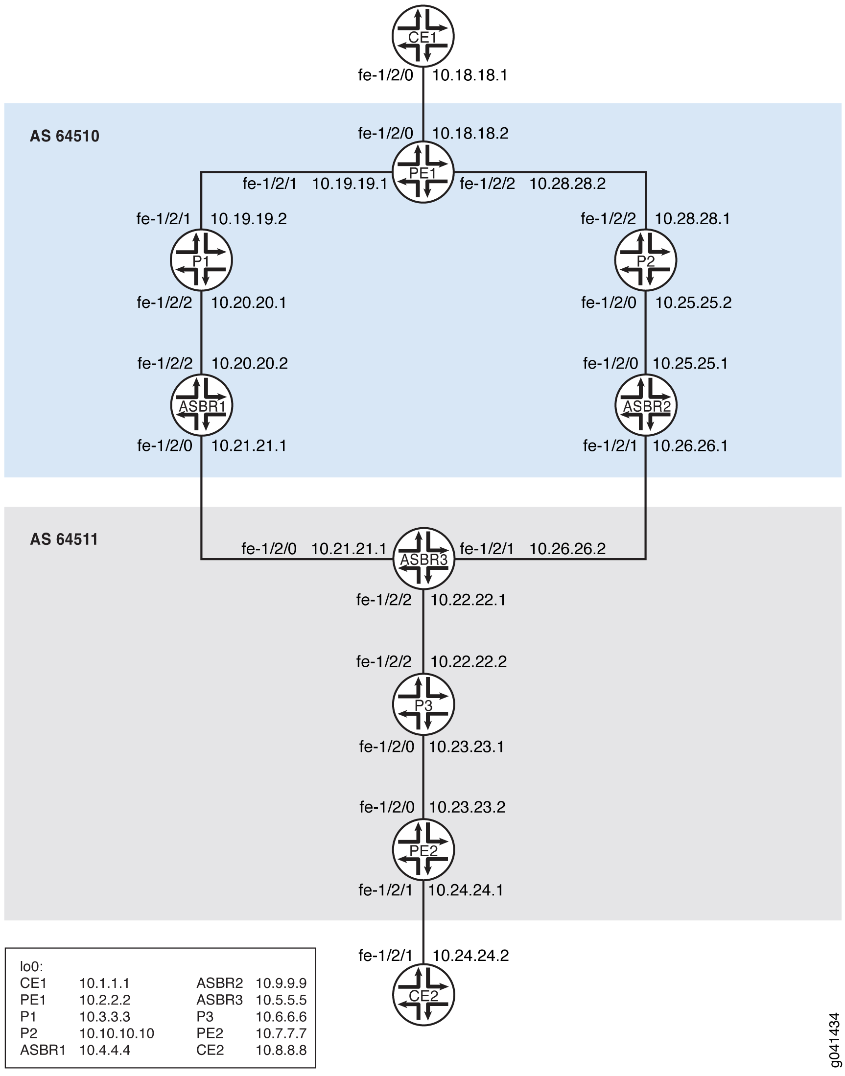
In Figure 3, autonomous system border routers (ASBRs) run external BGP (EBGP) to ASBRs in another autonomous system (AS) to exchange labels for /32 IPv4 routes. Inside the ASs, internal BGP (IBGP) propagates the routes to provider edge (PE) devices. If the link from Device ASBR3 to Device ASBR1 goes down, until Device ASBR3 reinstalls the new next hop, all traffic going toward AS 64510 from AS 64511 through the ASBR3-ASBR1 link is dropped. A fast traffic restoration can be achieved if Device ASBR3 preprograms a backup path either through Device ASBR4 or through a direct path to Device ASBR2 if one exists (not shown in the diagram). This assumes that Device ASBR3 learns a loop-free MPLS path for routes that need to protected either through IBGP or EBGP.
This solution does not handle a failure on Device ASBR3 for traffic going toward AS 64511 from AS 64510 through the ASBR3-ASBR1 link. This solution is limited to downstream inter-AS link-node protection with labeled BGP. This solution does not support service restoration between provider (P) and ASBR routers when there is an ASBR failure. For example, this solution does not handle a failure on the P3-ASBR3 link.
This supported functionality is similar to BGP multipath, except only one next hop is used for active forwarding, and a second path is in protected mode.
In an MPLS inter-AS environment, link protection can be enabled
when labeled-unicast is used to send traffic between ASs.
Hence, MPLS inter-AS link protection is configured on the link between
two routers in different ASs.
To configure link protection on an interface, use the protection statement at the [edit protocols bgp group group-name family inet labeled-unicast] hierarchy level:
protocols {
    bgp {
        group test1 {
            type external;
            local-address 192.168.1.2;
            family inet {
                labeled-unicast {
                    protection;
                }
            }
        }
    }
}
MPLS inter-AS link protection is supported only with labeled-unicast and external peers in a master routing instance.
The link on which protection is configured is known as the protection path. A protection path is selected only after the best path selection and is not selected in the following cases:
The best path is a non-BGP path.
Multiple next hops are active, as in BGP multipath.
Example: Configuring MPLS Inter-AS Link-Node Protection
This example shows how to configure tail-end protection in an inter-AS deployment with Layer 3 VPNs.
Requirements
No special configuration beyond device initialization is required before configuring this example.
Overview
In Figure 4. autonomous system border routers (ASBRs) run external BGP (EBGP) to ASBRs in another autonomous system (AS) to exchange labels for /32 IPv4 routes. Inside the ASs, internal BGP (IBGP) propagates the routes to provider edge (PE) devices.
If the link from Device ASBR3 to Device ASBR1 goes down, until ASBR3 reinstalls the new next hop, all traffic going toward AS 64510 from AS 64511 through the ASBR3-ASBR1 link is dropped.
This example shows how to achieve fast traffic restoration by configuring Device ASBR3 to preprogram a backup path through Device ASBR2.
This solution does not handle the Device P3 to Device ASBR3 failure. Nor does it handle a failure on Device ASBR3 for traffic going toward AS 645111 from AS 64510 through the ASBR3-ASBR1 link. This traffic is dropped.
Topology
Configuration
CLI Quick Configuration
To quickly configure this example, copy the following commands, paste them into a
text file, remove any line breaks, change any details necessary to match your
network configuration, and then copy and paste the commands into the CLI at the
[edit] hierarchy level.
Device ASBR1
set interfaces fe-1/2/2 unit 0 family inet address 10.20.20.2/30
set interfaces fe-1/2/2 unit 0 family mpls
set interfaces fe-1/2/0 unit 0 family inet address 10.21.21.1/30
set interfaces fe-1/2/0 unit 0 family mpls
set interfaces lo0 unit 0 family inet address 10.4.4.4/32
set protocols rsvp interface fe-1/2/2.0
set protocols rsvp interface lo0.0
set protocols mpls traffic-engineering bgp-igp-both-ribs
set protocols mpls label-switched-path To_PE1 to 10.2.2.2
set protocols mpls interface fe-1/2/2.0
set protocols mpls interface fe-1/2/0.0
set protocols mpls interface lo0.0
set protocols bgp group To-PE1 type internal
set protocols bgp group To-PE1 local-address 10.4.4.4
set protocols bgp group To-PE1 family inet unicast
set protocols bgp group To-PE1 family inet labeled-unicast
set protocols bgp group To-PE1 export next-hop-self
set protocols bgp group To-PE1 neighbor 10.2.2.2 family inet labeled-unicast
set protocols bgp group To-ASBR3 type external
set protocols bgp group To-ASBR3 family inet labeled-unicast
set protocols bgp group To-ASBR3 export To-ASBR3
set protocols bgp group To-ASBR3 neighbor 10.21.21.2 peer-as 64511
set protocols ospf traffic-engineering
set protocols ospf area 0.0.0.0 interface fe-1/2/2.0
set protocols ospf area 0.0.0.0 interface lo0.0 passive
set policy-options policy-statement To-ASBR3 term 1 from route-filter 10.2.2.2/32 exact
set policy-options policy-statement To-ASBR3 term 1 then accept
set policy-options policy-statement To-ASBR3 term 2 then reject
set policy-options policy-statement next-hop-self then next-hop self
set routing-options autonomous-system 64510
Device ASBR2
set interfaces fe-1/2/0 unit 0 description to-P2
set interfaces fe-1/2/0 unit 0 family inet address 10.25.25.1/30
set interfaces fe-1/2/0 unit 0 family mpls
set interfaces fe-1/2/1 unit 0 description to-ASBR3
set interfaces fe-1/2/1 unit 0 family inet address 10.26.26.1/30
set interfaces fe-1/2/1 unit 0 family mpls
set interfaces lo0 unit 0 family inet address 10.9.9.9/32
set protocols rsvp interface fe-1/2/0.0
set protocols rsvp interface lo0.0
set protocols mpls traffic-engineering bgp-igp-both-ribs
set protocols mpls label-switched-path To_PE1 to 10.2.2.2
set protocols mpls interface fe-1/2/0.0
set protocols mpls interface fe-1/2/1.0
set protocols mpls interface lo0.0
set protocols bgp group To-PE1 type internal
set protocols bgp group To-PE1 local-address 10.9.9.9
set protocols bgp group To-PE1 family inet unicast
set protocols bgp group To-PE1 family inet labeled-unicast
set protocols bgp group To-PE1 export next-hop-self
set protocols bgp group To-PE1 neighbor 10.2.2.2 family inet labeled-unicast
set protocols bgp group To-ASBR3 type external
set protocols bgp group To-ASBR3 family inet labeled-unicast
set protocols bgp group To-ASBR3 export To-ASBR3
set protocols bgp group To-ASBR3 neighbor 10.26.26.2 peer-as 64511
set protocols ospf traffic-engineering
set protocols ospf area 0.0.0.0 interface fe-1/2/0.0
set protocols ospf area 0.0.0.0 interface lo0.0 passive
set policy-options policy-statement To-ASBR3 term 1 from route-filter 10.2.2.2/32 exact
set policy-options policy-statement To-ASBR3 term 1 then accept
set policy-options policy-statement To-ASBR3 term 2 then reject
set policy-options policy-statement next-hop-self then next-hop self
set routing-options autonomous-system 64510
Device ASBR3
set interfaces fe-1/2/0 unit 0 description to-ASBR1
set interfaces fe-1/2/0 unit 0 family inet address 10.21.21.2/30
set interfaces fe-1/2/0 unit 0 family mpls
set interfaces fe-1/2/2 unit 0 description to-P3
set interfaces fe-1/2/2 unit 0 family inet address 10.22.22.1/30
set interfaces fe-1/2/2 unit 0 family mpls
set interfaces fe-1/2/1 unit 0 description to-ASBR2
set interfaces fe-1/2/1 unit 0 family inet address 10.26.26.2/30
set interfaces fe-1/2/1 unit 0 family mpls
set interfaces lo0 unit 0 family inet address 10.5.5.5/32
set protocols rsvp interface fe-1/2/2.0
set protocols rsvp interface lo0.0
set protocols rsvp interface fe-1/2/0.0
set protocols rsvp interface fe-1/2/1.0
set protocols mpls traffic-engineering bgp-igp-both-ribs
set protocols mpls label-switched-path To_PE2 to 10.7.7.7
set protocols mpls interface lo0.0
set protocols mpls interface fe-1/2/0.0
set protocols mpls interface fe-1/2/2.0
set protocols mpls interface fe-1/2/1.0
set protocols bgp group To-PE2 type internal
set protocols bgp group To-PE2 local-address 10.5.5.5
set protocols bgp group To-PE2 family inet unicast
set protocols bgp group To-PE2 export next-hop-self
set protocols bgp group To-PE2 neighbor 10.7.7.7 family inet labeled-unicast
set protocols bgp group To-ASBR1 type external
set protocols bgp group To-ASBR1 family inet labeled-unicast protection
set protocols bgp group To-ASBR1 family inet labeled-unicast per-prefix-label
set protocols bgp group To-ASBR1 export To-ASBR1
set protocols bgp group To-ASBR1 neighbor 10.21.21.1 peer-as 64510
set protocols bgp group To-ASBR2 type external
set protocols bgp group To-ASBR2 family inet labeled-unicast protection
set protocols bgp group To-ASBR2 family inet labeled-unicast per-prefix-label
set protocols bgp group To-ASBR2 export To-ASBR2
set protocols bgp group To-ASBR2 neighbor 10.26.26.1 peer-as 64510
set protocols ospf traffic-engineering
set protocols ospf area 0.0.0.0 interface fe-1/2/2.0
set protocols ospf area 0.0.0.0 interface lo0.0 passive
set protocols ospf area 0.0.0.0 interface fe-1/2/1.0
set policy-options policy-statement To-ASBR1 term 1 from route-filter 10.7.7.7/32 exact
set policy-options policy-statement To-ASBR1 term 1 then accept
set policy-options policy-statement To-ASBR1 term 2 then reject
set policy-options policy-statement To-ASBR2 term 1 from route-filter 10.7.7.7/32 exact
set policy-options policy-statement To-ASBR2 term 1 then accept
set policy-options policy-statement To-ASBR2 term 2 then reject
set policy-options policy-statement next-hop-self then next-hop self
set routing-options autonomous-system 64511
Device CE1
set interfaces fe-1/2/0 unit 0 family inet address 10.18.18.1/30
set interfaces lo0 unit 0 family inet address 10.1.1.1/32
set protocols ospf area 0.0.0.2 interface fe-1/2/0.0
set protocols ospf area 0.0.0.2 interface lo0.0 passive
Device CE2
set interfaces fe-1/2/1 unit 0 family inet address 10.24.24.2/30
set interfaces lo0 unit 0 family inet address 10.8.8.8/32
set protocols bgp group To_PE2 neighbor 10.24.24.1 export myroutes
set protocols bgp group To_PE2 neighbor 10.24.24.1 peer-as 64511
set policy-options policy-statement myroutes from protocol direct
set policy-options policy-statement myroutes then accept
set routing-options autonomous-system 64509
Device P1
set interfaces fe-1/2/1 unit 0 family inet address 10.19.19.2/30
set interfaces fe-1/2/1 unit 0 family mpls
set interfaces fe-1/2/2 unit 0 family inet address 10.20.20.1/30
set interfaces fe-1/2/2 unit 0 family mpls
set interfaces lo0 unit 0 family inet address 10.3.3.3/32
set protocols rsvp interface fe-1/2/1.0
set protocols rsvp interface fe-1/2/2.0
set protocols rsvp interface lo0.0
set protocols mpls interface fe-1/2/1.0
set protocols mpls interface fe-1/2/2.0
set protocols mpls interface lo0.0
set protocols ospf traffic-engineering
set protocols ospf area 0.0.0.0 interface fe-1/2/1.0
set protocols ospf area 0.0.0.0 interface fe-1/2/2.0
set protocols ospf area 0.0.0.0 interface lo0.0 passive
Device P2
set interfaces fe-1/2/0 unit 0 description to-ASBR2
set interfaces fe-1/2/0 unit 0 family inet address 10.25.25.2/30
set interfaces fe-1/2/0 unit 0 family mpls
set interfaces fe-1/2/2 unit 0 description to-PE1
set interfaces fe-1/2/2 unit 0 family inet address 10.28.28.1/30
set interfaces fe-1/2/2 unit 0 family mpls
set interfaces lo0 unit 0 family inet address 10.10.10.10/32
set protocols rsvp interface fe-1/2/0.0
set protocols rsvp interface fe-1/2/2.0
set protocols rsvp interface lo0.0
set protocols mpls interface fe-1/2/0.0
set protocols mpls interface fe-1/2/2.0
set protocols mpls interface lo0.0
set protocols ospf traffic-engineering
set protocols ospf area 0.0.0.0 interface fe-1/2/0.0
set protocols ospf area 0.0.0.0 interface fe-1/2/2.0
set protocols ospf area 0.0.0.0 interface lo0.0 passive
Device P3
set interfaces fe-1/2/2 unit 0 family inet address 10.22.22.2/30
set interfaces fe-1/2/2 unit 0 family mpls
set interfaces fe-1/2/0 unit 0 family inet address 10.23.23.1/30
set interfaces fe-1/2/0 unit 0 family mpls
set interfaces lo0 unit 0 family inet address 10.6.6.6/32
set protocols rsvp interface fe-1/2/2.0
set protocols rsvp interface fe-1/2/0.0
set protocols rsvp interface lo0.0
set protocols mpls interface fe-1/2/2.0
set protocols mpls interface fe-1/2/0.0
set protocols mpls interface lo0.0
set protocols ospf traffic-engineering
set protocols ospf area 0.0.0.0 interface fe-1/2/2.0
set protocols ospf area 0.0.0.0 interface fe-1/2/0.0
set protocols ospf area 0.0.0.0 interface lo0.0 passive
Device PE1
set interfaces fe-1/2/0 unit 0 family inet address 10.18.18.2/30
set interfaces fe-1/2/1 unit 0 family inet address 10.19.19.1/30
set interfaces fe-1/2/1 unit 0 family mpls
set interfaces fe-1/2/2 unit 0 description to-P2
set interfaces fe-1/2/2 unit 0 family inet address 10.28.28.2/30
set interfaces lo0 unit 0 family inet address 10.2.2.2/32
set protocols rsvp interface fe-1/2/0.0
set protocols rsvp interface lo0.0
set protocols rsvp interface fe-1/2/2.0
set protocols mpls label-switched-path To-ASBR1 to 10.4.4.4
set protocols mpls label-switched-path To-ASBR2 to 10.9.9.9
set protocols mpls interface fe-1/2/0.0
set protocols mpls interface lo0.0
set protocols mpls interface fe-1/2/2.0
set protocols bgp group To_ASBR1 type internal
set protocols bgp group To_ASBR1 local-address 10.2.2.2
set protocols bgp group To_ASBR1 family inet labeled-unicast
set protocols bgp group To_ASBR1 neighbor 10.4.4.4 family inet labeled-unicast resolve-vpn
set protocols bgp group To_PE2 type external
set protocols bgp group To_PE2 multihop ttl 20
set protocols bgp group To_PE2 local-address 10.2.2.2
set protocols bgp group To_PE2 family inet-vpn unicast
set protocols bgp group To_PE2 neighbor 10.7.7.7 peer-as 64511
set protocols bgp group To_ASBR2 type internal
set protocols bgp group To_ASBR2 local-address 10.2.2.2
set protocols bgp group To_ASBR2 family inet labeled-unicast
set protocols bgp group To_ASBR2 neighbor 10.9.9.9 family inet labeled-unicast resolve-vpn
set protocols ospf traffic-engineering
set protocols ospf area 0.0.0.0 interface fe-1/2/0.0
set protocols ospf area 0.0.0.0 interface lo0.0 passive
set protocols ospf area 0.0.0.0 interface fe-1/2/2.0
set policy-options policy-statement bgp-to-ospf term 1 from protocol bgp
set policy-options policy-statement bgp-to-ospf term 1 then accept
set policy-options policy-statement bgp-to-ospf term 2 then reject
set policy-options policy-statement vpnexport term 1 from protocol ospf
set policy-options policy-statement vpnexport term 1 then community add test_comm
set policy-options policy-statement vpnexport term 1 then accept
set policy-options policy-statement vpnexport term 2 then reject
set policy-options policy-statement vpnimport term 1 from protocol bgp
set policy-options policy-statement vpnimport term 1 from community test_comm
set policy-options policy-statement vpnimport term 1 then accept
set policy-options policy-statement vpnimport term 2 then reject
set policy-options community test_comm members target:1:64510
set routing-instances vpn2CE1 instance-type vrf
set routing-instances vpn2CE1 interface fe-1/2/0.0
set routing-instances vpn2CE1 route-distinguisher 1:64510
set routing-instances vpn2CE1 vrf-import vpnimport
set routing-instances vpn2CE1 vrf-export vpnexport
set routing-instances vpn2CE1 protocols ospf export bgp-to-ospf
set routing-instances vpn2CE1 protocols ospf area 0.0.0.2 interface fe-1/2/0.0
set routing-options autonomous-system 64510
Device PE2
set interfaces fe-1/2/0 unit 0 family inet address 10.23.23.2/30
set interfaces fe-1/2/0 unit 0 family mpls
set interfaces fe-1/2/1 unit 0 family inet address 10.24.24.1/30
set interfaces lo0 unit 0 family inet address 10.7.7.7/32
set protocols rsvp interface fe-1/2/0.0
set protocols rsvp interface lo0.0
set protocols mpls label-switched-path To-ASBR3 to 10.5.5.5
set protocols mpls interface fe-1/2/0.0
set protocols mpls interface lo0.0
set protocols bgp group To_ASBR3 type internal
set protocols bgp group To_ASBR3 local-address 10.7.7.7
set protocols bgp group To_ASBR3 family inet labeled-unicast
set protocols bgp group To_ASBR3 neighbor 10.5.5.5 family inet labeled-unicast resolve-vpn
set protocols bgp group To_PE1 type external
set protocols bgp group To_PE1 multihop ttl 20
set protocols bgp group To_PE1 local-address 10.7.7.7
set protocols bgp group To_PE1 family inet-vpn unicast
set protocols bgp group To_PE1 neighbor 10.2.2.2 peer-as 64510
set protocols ospf traffic-engineering
set protocols ospf area 0.0.0.0 interface fe-1/2/0.0
set protocols ospf area 0.0.0.0 interface lo0.0 passive
set policy-options policy-statement vpnexport term 1 from protocol bgp
set policy-options policy-statement vpnexport term 1 then community add test_comm
set policy-options policy-statement vpnexport term 1 then accept
set policy-options policy-statement vpnexport term 2 then reject
set policy-options policy-statement vpnimport term 1 from protocol bgp
set policy-options policy-statement vpnimport term 1 from community test_comm
set policy-options policy-statement vpnimport term 1 then accept
set policy-options policy-statement vpnimport term 2 then reject
set policy-options community test_comm members target:1:64510
set routing-instances vpn2CE2 instance-type vrf
set routing-instances vpn2CE2 interface fe-1/2/1.0
set routing-instances vpn2CE2 route-distinguisher 1:64510
set routing-instances vpn2CE2 vrf-import vpnimport
set routing-instances vpn2CE2 vrf-export vpnexport
set routing-instances vpn2CE2 protocols bgp group To_CE2 peer-as 64509
set routing-instances vpn2CE2 protocols bgp group To_CE2 neighbor 10.24.24.2
set routing-options autonomous-system 64511
Procedure
Step-by-Step Procedure
The following example requires you to navigate various levels in the configuration hierarchy. For information about navigating the CLI, see Using the CLI Editor in Configuration Mode in the Junos OS CLI User Guide.
To configure the EBGP scenario:
-
Configure the router interfaces.
[edit interfaces]
user@ASBR3# set fe-1/2/0 unit 0 description to-ASBR1
user@ASBR3# set fe-1/2/0 unit 0 family inet address 10.21.21.2/30
user@ASBR3# set fe-1/2/0 unit 0 family mpls
user@ASBR3# set fe-1/2/2 unit 0 description to-P3
user@ASBR3# set fe-1/2/2 unit 0 family inet address 10.22.22.1/30
user@ASBR3# set fe-1/2/2 unit 0 family mpls
user@ASBR3# set fe-1/2/1 unit 0 description to-ASBR2
user@ASBR3# set fe-1/2/1 unit 0 family inet address 10.26.26.2/30
user@ASBR3# set fe-1/2/1 unit 0 family mpls
user@ASBR3# set lo0 unit 0 family inet address 10.5.5.5/32
-
Configure an interior gateway protocol (IGP), such as OSPF or IS-IS.
[edit protocols ospf]
user@ASBR3# set traffic-engineering
[edit protocols ospf area 0.0.0.0]
user@ASBR3# set interface fe-1/2/2.0
user@ASBR3# set interface lo0.0 passive
user@ASBR3# set interface fe-1/2/1.0
-
Configure the autonomous system (AS) number.
[edit routing-options]
user@ASBR3# set autonomous-system 64511
-
Configure the routing policy.
[edit policy-options policy-statement To-ASBR1]
user@ASBR3# set term 1 from route-filter 10.7.7.7/32 exact
user@ASBR3# set term 1 then accept
user@ASBR3# set term 2 then reject
[edit policy-options policy-statement To-ASBR2]
user@ASBR3# set term 1 from route-filter 10.7.7.7/32 exact
user@ASBR3# set term 1 then accept
user@ASBR3# set term 2 then reject
[edit policy-options policy-statement next-hop-self]
user@ASBR3# set then next-hop self
-
Configure the EBGP sessions.
[edit protocols bgp group To-ASBR1]
user@ASBR3# set type external
user@ASBR3# set family inet labeled-unicast protection
user@ASBR3# set family inet labeled-unicast per-prefix-label
user@ASBR3# set export To-ASBR1
user@ASBR3# set neighbor 10.21.21.1 peer-as 64510
[edit protocols bgp group To-ASBR2]
user@ASBR3# set type external
user@ASBR3# set family inet labeled-unicast protection
user@ASBR3# set family inet labeled-unicast per-prefix-label
user@ASBR3# set export To-ASBR2
user@ASBR3# set neighbor 10.26.26.1 peer-as 64510
-
Configure the IBGP sessions.
[edit protocols bgp group To-PE2]
user@ASBR3# set type internal
user@ASBR3# set local-address 10.5.5.5
user@ASBR3# set family inet unicast
user@ASBR3# set export next-hop-self
user@ASBR3# set neighbor 10.7.7.7 family inet labeled-unicast
-
Configure MPLS.
[edit protocols mpls]
user@ASBR3# set traffic-engineering bgp-igp-both-ribs
user@ASBR3# set label-switched-path To_PE2 to 10.7.7.7
user@ASBR3# set interface lo0.0
user@ASBR3# set interface fe-1/2/0.0
user@ASBR3# set interface fe-1/2/2.0
user@ASBR3# set interface fe-1/2/1.0
-
Configure a signaling protocol.
[edit protocols rsvp]
user@ASBR3# set interface fe-1/2/2.0
user@ASBR3# set interface lo0.0
user@ASBR3# set interface fe-1/2/0.0
user@ASBR3# set interface fe-1/2/1.0
Results
From configuration mode, confirm your configuration by entering the
show interfaces, show protocols,
show policy-options, and show
routing-options, commands. If the output does not display the
intended configuration, repeat the instructions in this example to correct
the configuration.
user@ASBR3# show interfaces
fe-1/2/0 {
    unit 0 {
        description to-ASBR1;
        family inet {
            address 10.21.21.2/30;
        }
        family mpls;
    }
}
fe-1/2/1 {
    unit 0 {
        description to-ASBR2;
        family inet {
            address 10.26.26.2/30;
        }
        family mpls;
    }
}
fe-1/2/2 {
    unit 0 {
        description to-P3;
        family inet {
            address 10.22.22.1/30;
        }
        family mpls;
    }
}
lo0 {
    unit 0 {
        family inet {
            address 10.5.5.5/32;
        }
    }
}
user@ASBR3# show protocols
rsvp {
    interface fe-1/2/2.0;
    interface lo0.0;
    interface fe-1/2/0.0;
    interface fe-1/2/1.0;
}
mpls {
    traffic-engineering bgp-igp-both-ribs;
    label-switched-path To_PE2 {
        to 10.7.7.7;
    }
    interface lo0.0;
    interface fe-1/2/0.0;
    interface fe-1/2/2.0;
    interface fe-1/2/1.0;
}
bgp {
    group To-PE2 {
        type internal;
        local-address 10.5.5.5;
        family inet {
            unicast;
        }
        export next-hop-self;
        neighbor 10.7.7.7 {
            family inet {
                labeled-unicast;
            }
        }
    }
    group To-ASBR1 {
        type external;
        family inet {
            labeled-unicast {
                protection;
            }
        }
        export To-ASBR1;
        neighbor 10.21.21.1 {
            peer-as 64510;
        }
    }
    group To-ASBR2 {
        type external;
        family inet {
            labeled-unicast {
                protection;
            }
        }
        export To-ASBR2;
        neighbor 10.26.26.1 {
            peer-as 64510;
        }
    }
}
ospf {
    traffic-engineering;
    area 0.0.0.0 {
        interface fe-1/2/2.0;
        interface lo0.0 {
            passive;
        }
        interface fe-1/2/1.0;
    }
}
user@ASBR3# show policy-options
policy-statement To-ASBR1 {
    term 1 {
        from {
            route-filter 10.7.7.7/32 exact;
        }
        then accept;
    }
    term 2 {
        then reject;
    }
}
policy-statement To-ASBR2 {
    term 1 {
        from {
            route-filter 10.7.7.7/32 exact;
        }
        then accept;
    }
    term 2 {
        then reject;
    }
}
policy-statement next-hop-self {
    then {
        next-hop self;
    }
}
user@ASBR3# show routing-options
autonomous-system 64511;
If you are done configuring the devices, enter commit from
configuration mode.
Verification
Confirm that the configuration is working properly.
Checking the BGP Neighbor Sessions
Purpose
Verify that BGP protection is enabled.
Action
user@ASBR3# show bgp neighbor 10.21.21.1
Peer:10.21.21.1+58259 AS 64510 Local: 10.21.21.2+179 AS 64511
  Type: External    State: Established    Flags: <ImportEval Sync>
  Last State: OpenConfirm   Last Event: RecvKeepAlive
  Last Error: None
  Export: [ To-ASBR1 ]
  Options: <Preference AddressFamily PeerAS Refresh>
  Options: <Protection>
  Address families configured: inet-labeled-unicast
  Holdtime: 90 Preference: 170
  NLRI configured with protection: inet-labeled-unicast
  Number of flaps: 0
  Peer ID: 10.4.4.4         Local ID: 10.5.5.5           Active Holdtime: 90
  Keepalive Interval: 30         Group index: 4    Peer index: 0
  BFD: disabled, down
  Local Interface: fe-1/2/0.0
  NLRI for restart configured on peer: inet-labeled-unicast
  NLRI advertised by peer: inet-labeled-unicast
  NLRI for this session: inet-labeled-unicast
  Peer supports Refresh capability (2)
  Stale routes from peer are kept for: 300
  Peer does not support Restarter functionality
  NLRI that restart is negotiated for: inet-labeled-unicast
  NLRI of received end-of-rib markers: inet-labeled-unicast
  NLRI of all end-of-rib markers sent: inet-labeled-unicast
  Peer supports 4 byte AS extension (peer-as 64510)
  Peer does not support Addpath
  Table inet.0 Bit: 10001
    RIB State: BGP restart is complete
    Send state: in sync
    Active prefixes:              2
    Received prefixes:            1
    Accepted prefixes:            1
    Suppressed due to damping:    0
    Advertised prefixes:          1
  Last traffic (seconds): Received 7    Sent 20   Checked 32
  Input messages:  Total 170    Updates 2       Refreshes 0     Octets 3326
  Output messages: Total 167    Updates 1       Refreshes 0     Octets 3288
Output Queue[0]: 0user@ASBR3# show bgp neighbor 10.26.26.1
Peer: 10.26.26.1+61072 AS 64510 Local: 10.26.26.2+179 AS 64511
Type: External State: Established Flags: <ImportEval Sync>
Last State: OpenConfirm Last Event: RecvKeepAlive
Last Error: None
Export: [ To-ASBR2 ]
Options: <Preference AddressFamily PeerAS Refresh>
Options: <Protection>
Address families configured: inet-labeled-unicast
Holdtime: 90 Preference: 170
NLRI configured with protection:
                            inet-labeled-unicast
Number of flaps: 0
Peer ID: 10.9.9.9 Local ID: 10.5.5.5 Active Holdtime: 90
Keepalive Interval: 30 Group index: 5 Peer index: 0
BFD: disabled, down
Local Interface: fe-1/2/1.0
NLRI for restart configured on peer: inet-labeled-unicast
NLRI advertised by peer: inet-labeled-unicast
NLRI for this session: inet-labeled-unicast
Peer supports Refresh capability (2)
Stale routes from peer are kept for: 300
Peer does not support Restarter functionality
NLRI that restart is negotiated for: inet-labeled-unicast
NLRI of received end-of-rib markers: inet-labeled-unicast
NLRI of all end-of-rib markers sent: inet-labeled-unicast
Peer supports 4 byte AS extension (peer-as 64510)
Peer does not support Addpath
Table inet.0 Bit: 10002
RIB State: BGP restart is complete
Send state: in sync
Active prefixes: 1
Received prefixes: 1
Accepted prefixes: 1
Suppressed due to damping: 0
Advertised prefixes: 1
Last traffic (seconds): Received 21 Sent 9 Checked 42
Input messages: Total 170 Updates 2 Refreshes 0 Octets 3326
Output messages: Total 168 Updates 1 Refreshes 0 Octets 3307
Output Queue[0]: 0Meaning
The output shows that the Protection option is enabled for
the EBGP peers, Device ASBR1 and Device ASBR2.
This is also shown with the NLRI configured with protection:
inet-labeled-unicast screen output.
Checking the Routes
Purpose
Make sure that the backup path is installed in the routing table.
Action
user@ASBR3> show route 10.2.2.2
inet.0: 12 destinations, 14 routes (12 active, 0 holddown, 0 hidden)
+ = Active Route, - = Last Active, * = Both

10.2.2.2/32         *[BGP/170] 01:36:25, MED 2, localpref 100
                      AS path: 64510 I, validation-state: unverified
                    > to 10.21.21.1 via fe-1/2/0.0, Push 299824
                      to 10.26.26.1 via fe-1/2/1.0, Push 299808
                    [BGP/170] 01:36:25, MED 2, localpref 100
                      AS path: 64510 I, validation-state: unverified
                    > to 10.26.26.1 via fe-1/2/1.0, Push 299808
Meaning
The show route command displays active as well as backup
paths to Device PE1.
Configuring Egress Protection Service Mirroring for BGP Signaled Layer 2 Services
Starting in Junos OS Release 14.2, Junos OS supports the restoration of egress traffic when there is a link or node failure in the egress PE node. If there is a link or node failure in the core network, a protection mechanism such as MPLS fast reroute can be triggered on the transport LSPs between the PE routers to repair the connection within tens of milliseconds. An egress protection LSP addresses the problem of a node-link failure at the edge of the network (for example, a failure of a PE router).
Figure 1 shows a simplified topology of the use case that explains this feature.
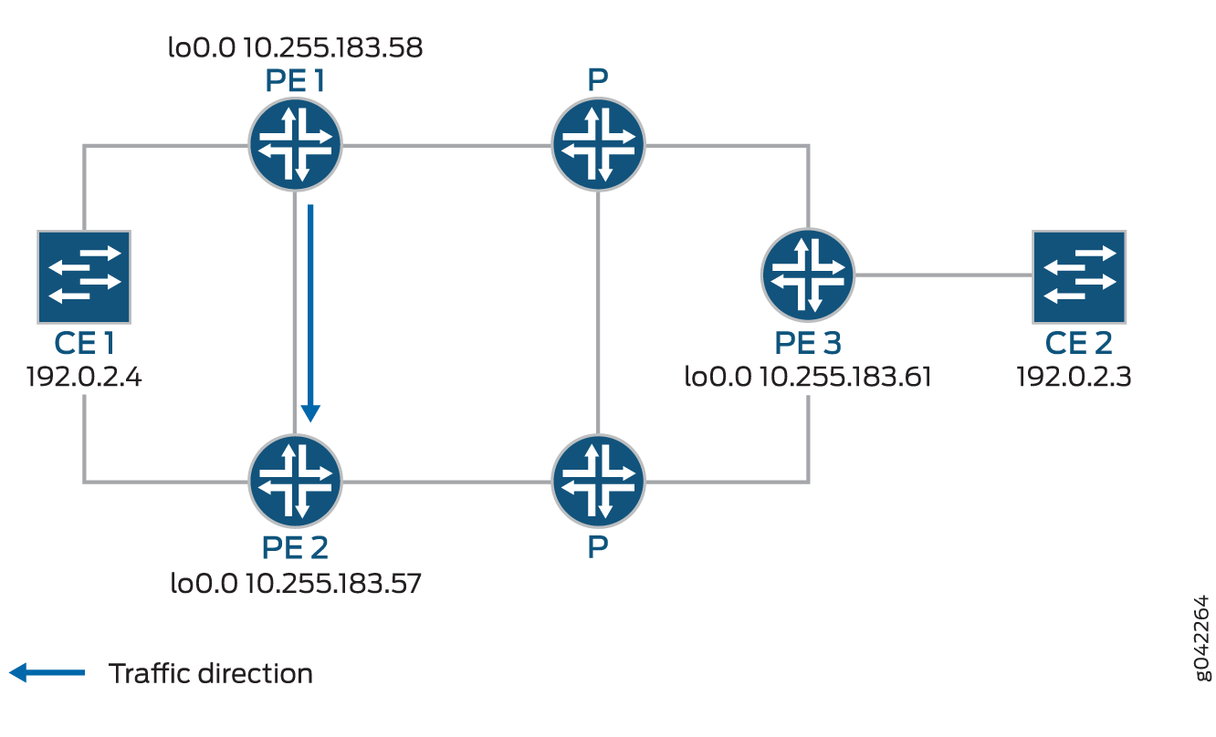
CE1 is multihomed to PE1 and PE2. There are two paths connecting CE1 and CE2. The working path is CE2-PE3-P-PE1-CE1, via pseudowire PW21. The protecting path is CE2-PE3-P-PE2-CE1, via pseudowire PW22 Traffic is flowing through the working path under normal circumstances. When the end-to-end OAM between CE1 and CE2 detects failure on the working path, traffic will be switched from the working path to the protecting path. The end-to-end failure detection and recovery relies on control plane hence should be relatively slow. To achieve faster protection, local repair mechanisms similar to those used by MPLS fast reroute should be used. In Figure 1 above, if link or node failed in the core network (like link failure on P-PE1, P-PE3, or node failure on P), the MPLS fast reroute will happen on the transport LSPs between PE1 and PE3. The failure could be locally repaired within tens of milliseconds. However, if link or node failure happens at the edge (like link failure on PE3-CE2 or node failure on PE3), there is no local repair currently so we have to rely on the CE1-CE2 end-to-end protection to repair the failure.
Device CE2—Traffic origin
Router PE3—Ingress PE router
Router PE1— (Primary) Egress PE router
Router PE2—Protector PE router
Device CE1—Traffic destination
When the link between CE1– PE1 goes downs, PE1 will briefly redirect that traffic towards CE1, to PE2. PE2 forwards it to CE1 until ingress router PE3 recalculates to forward the traffic to PE2.
Initially the traffic direction was; CE2 – PE3 – P – PE1 – CE1.
When the link between CE1– PE1 goes down, the traffic will be; CE2 – PE3 – P – PE1 – PE2 –CE1. PE3 then recalculates the path; CE2 – PE3 – P – PE2 – CE1.
Example: Configuring MPLS Egress Protection Service Mirroring for BGP Signaled Layer 2 Services
Starting in Junos OS Release 14.2, Junos OS supports the restoration of egress traffic when there is a link or node failure in the egress PE node. If there is a link or node failure in the core network, a protection mechanism such as MPLS fast reroute can be triggered on the transport LSPs between the PE routers to repair the connection within tens of milliseconds. An egress protection LSP addresses the problem of a node-link failure at the edge of the network (for example, a failure of a PE router).
This example shows how to configure link protection for BGP signaled Layer 2 services.
Requirements
MX Series Routers running Junos OS Release 14.2 or later.
Overview
If there is a link or node failure in the core network, a protection mechanism such as MPLS fast reroute can be triggered on the transport LSPs between the PE routers to repair the connection within tens of milliseconds. An egress protection LSP addresses the problem of a node-link failure at the edge of the network (for example, a failure of a PE router).
This example includes the following configuration concepts and statements that are unique to the configuration of an egress protection LSP:
context-identifier—Specifies an IPv4 or IPv6 address used to define the pair of PE routers participating in the egress protection LSP. It is assigned to each ordered pair of primary PE and the protector to facilitate protection establishment. This address is globally unique, or unique in the address space of the network where the primary PE and the protector reside.egress-protection—Configures the protector information for the protected Layer 2 circuit and configures the protector Layer 2 circuit at the[edit protocols mpls]hierarchy level. Configures an LSP as an egress protection LSP at the[edit protocols mpls]hierarchy level.protector—Configures the creation of standby pseudowires on the backup PE for link or node protection for the instance.
Topology

In the event of a failure of the egress PE Router PE1, traffic is switched to the egress protection LSP configured between Router PE1 and Router PE2 (the protector PE router):
Device CE2—Traffic origin
Router PE3—Ingress PE router
Router PE1— (Primary) Egress PE router
Router PE2—Protector PE router
Device CE1—Traffic destination
When the link between CE1– PE1 goes downs, PE1 will briefly redirect that traffic toward CE1, to PE2. PE2 forwards it to CE1 until ingress router PE3 recalculates to forward the traffic to PE2.
Initially the traffic direction was: CE2 – PE3 – P – PE1 – CE1.
When the link between CE1– PE1 goes down, the traffic will be: CE2 – PE3 – P – PE1 – PE2 –CE1. PE3 then recalculates the path: CE2 – PE3 – P – PE2 – CE1.
This example shows how to configure routers PE1, PE2, and PE3.
Configuration
CLI Quick Configuration
To quickly configure an egress protection
LSP, copy the following commands, paste them into a text file, remove
any line breaks, change any details necessary to match your network
configurations, copy and then paste the commands into the CLI and
enter commit from configuration mode.
PE1
set protocols rsvp interface all set protocols rsvp interface fxp0.0 disable set protocols mpls interface all set protocols mpls interface fxp0.0 disable set protocols mpls egress-protection context-identifier 198.51.100.3 primary set protocols mpls egress-protection context-identifier 198.51.100.3 advertise-mode stub-alias set protocols mpls egress-protection traceoptions file ep size 100m set protocols mpls egress-protection traceoptions flag all set protocols bgp traceoptions file bgp.log world-readable set protocols bgp group ibgp type internal set protocols bgp group ibgp local-address 10.255.183.58 set protocols bgp group ibgp family inet unicast set protocols bgp group ibgp family l2vpn signaling egress-protection set protocols bgp group ibgp neighbor 192.0.2.3 set protocols bgp group ibgp neighbor 192.0.2.4 set protocols isis traceoptions file isis-edge size 10m world-readable set protocols isis traceoptions flag error set protocols isis level 1 disable set protocols isis level 2 wide-metrics-only set protocols isis interface all point-to-point set protocols isis interface all level 2 metric 10 set protocols isis interface fxp0.0 disable set protocols ldp interface all set protocols ldp interface fxp0.0 disable set policy-options policy-statement lb then load-balance per-packet set routing-options traceoptions file ro.log set routing-options traceoptions flag all set routing-options traceoptions flag route set routing-options autonomous-system 100 set routing-options forwarding-table export lb set routing-instances foo instance-type l2vpn set routing-instances foo egress-protection context-identifier 198.51.100.3 set routing-instances foo interface ge-2/0/2.0 set routing-instances foo route-distinguisher 10.255.183.58:1 set routing-instances foo vrf-target target:9000:1 set routing-instances foo protocols l2vpn encapsulation-type ethernet-vlan set routing-instances foo protocols l2vpn site foo site-identifier 1 set routing-instances foo protocols l2vpn site foo site-preference primary set routing-instances foo protocols l2vpn site foo interface ge-2/0/2.0 remote-site-id 2
PE2
set protocols rsvp interface all set protocols rsvp interface fxp0.0 disable set protocols mpls interface all set protocols mpls interface fxp0.0 disable set protocols mpls egress-protection context-identifier 198.51.100.3 protector set protocols mpls egress-protection context-identifier 198.51.100.3 advertise-mode stub-alias set protocols mpls egress-protection traceoptions file ep size 100m set protocols mpls egress-protection traceoptions flag all set protocols bgp traceoptions file bgp.log world-readable set protocols bgp group ibgp type internal set protocols bgp group ibgp local-address 10.255.183.57 set protocols bgp group ibgp family inet unicast set protocols bgp group ibgp family l2vpn signaling egress-protection set protocols bgp group ibgp neighbor 192.0.2.3 set protocols bgp group ibgp neighbor 192.0.2.4 set protocols isis traceoptions file isis-edge size 10m world-readable set protocols isis traceoptions flag error set protocols isis level 1 disable set protocols isis level 2 wide-metrics-only set protocols isis interface all point-to-point set protocols isis interface all level 2 metric 10 set protocols isis interface fxp0.0 disable set protocols ldp interface all set protocols ldp interface fxp0.0 disable set policy-options policy-statement lb then load-balance per-packet set routing-options traceoptions file ro.log set routing-options traceoptions flag normal set routing-options traceoptions flag route set routing-options autonomous-system 100 set routing-options forwarding-table export lb set routing-instances foo instance-type l2vpn set routing-instances foo egress-protection protector set routing-instances foo interface ge-2/0/2.0 set routing-instances foo route-distinguisher 10.255.183.57:1 set routing-instances foo vrf-target target:9000:1 set routing-instances foo protocols l2vpn encapsulation-type ethernet-vlan set routing-instances foo protocols l2vpn site foo hot-standby set routing-instances foo protocols l2vpn site foo site-identifier 1 set routing-instances foo protocols l2vpn site foo site-preference backup set routing-instances foo protocols l2vpn site foo interface ge-2/0/2.0 remote-site-id 2
PE3
set protocols rsvp interface all set protocols rsvp interface fxp0.0 disable set protocols mpls interface all set protocols mpls interface fxp0.0 disable set protocols bgp traceoptions file bgp.log world-readable set protocols bgp group ibgp type internal set protocols bgp group ibgp local-address 10.255.183.61 set protocols bgp group ibgp family inet unicast set protocols bgp group ibgp family l2vpn signaling set protocols bgp group ibgp neighbor 192.0.2.3 set protocols bgp group ibgp neighbor 192.0.2.4 set protocols isis traceoptions file isis-edge size 10m world-readable set protocols isis traceoptions flag error set protocols isis level 1 disable set protocols isis level 2 wide-metrics-only set protocols isis interface all point-to-point set protocols isis interface all level 2 metric 10 set protocols isis interface fxp0.0 disable set protocols ldp interface all set protocols ldp interface fxp0.0 disable set policy-options policy-statement lb then load-balance per-packet set routing-options traceoptions file ro.log set routing-options traceoptions flag normal set routing-options traceoptions flag route set routing-options autonomous-system 100 set routing-options forwarding-table export lb set routing-instances foo instance-type l2vpn set routing-instances foo interface ge-2/1/2.0 set routing-instances foo route-distinguisher 10.255.183.61:1 set routing-instances foo vrf-target target:9000:1 set routing-instances foo protocols l2vpn encapsulation-type ethernet-vlan set routing-instances foo protocols l2vpn site foo site-identifier 2 set routing-instances foo protocols l2vpn site foo interface ge-2/1/2.0 remote-site-id 1
Step-by-Step Procedure
Step-by-Step Procedure
The following example requires you to navigate various levels in the configuration hierarchy. For information about navigating the CLI, see Using the CLI Editor in Configuration Mode.
To configure an egress protection LSP for router PE1:
Configure RSVP.
[edit protocols rsvp] user@PE1# set interface all user@PE1# set interface fxp0.0 disable
Configure MPLS to use the egress protection LSP to protect against a link failure to Device CE1.
[edit protocols mpls] user@PE1# set interface all user@PE1# set interface fxp0.0 disable user@PE1# set egress-protection context-identifier 198.51.100.3 primary user@PE1# set egress-protection context-identifier 198.51.100.3 advertise-mode stub-alias user@PE1# set egress-protection traceoptions file ep size 100m user@PE1# set egress-protection traceoptions flag all
Configure BGP.
[edit protocols bgp]
user@PE1# set traceoptions file bgp.log world-readable
user@PE1# set group ibgp type internal
user@PE1# set group ibgp local-address 10.255.183.58
user@PE1# set group ibgp family inet unicast
user@PE1# set group ibgp family l2vpn signaling egress-protection
user@PE1# set group ibgp neighbor 192.0.2.3
user@PE1# set group ibgp neighbor 192.0.2.4
Configure IS-IS.
[edit protocols isis]
user@PE1# set traceoptions file isis-edge size 10m world-readable
user@PE1# set traceoptions flag error
user@PE1# set level 1 disable
user@PE1# set level 2 wide-metrics-only
user@PE1# set interface all point-to-point
user@PE1# set interface all level 2 metric 10
user@PE1# set interface fxp0.0 disable
Configure LDP.
[edit protocols ldp]
user@PE1# set interface all
user@PE1# set interface fxp0.0 disable
Configure a load-balancing policy.
[edit]
user@PE1# set policy-options policy-statement lb then load-balance per-packet
Configure the routing options to export routes based on the load-balancing policy.
[edit routing-options]
user@PE1# set traceoptions file ro.log
user@PE1# set traceoptions flag all
user@PE1# set autonomous-system 100
user@PE1# set forwarding-table export lb
Configure BGP to advertise nrli from the routing instance with context-ID as next-hop.
[edit routing-instances]
user@PE1# set foo instance-type l2vpn
user@PE1# set foo egress-protection context-identifier 198.51.100.3
user@PE1# set foo interface ge-2/0/2.0
user@PE1# set foo route-distinguisher 10.255.183.58:1
user@PE1# set foo vrf-target target:9000:1
Configure l2vpn instance to use the egress LSP configured.
[edit routing-instances]
user@PE1# set foo protocols l2vpn encapsulation-type ethernet-vlan
user@PE1# set foo protocols l2vpn site foo site-identifier 1
user@PE1# set foo protocols l2vpn site foo site-preference primary
user@PE1# set foo protocols l2vpn site foo interface ge-2/0/2.0 remote-site-id 2
If you are done configuring the device, enter
commitfrom configuration mode.
Step-by-Step Procedure
To configure an egress protection LSP for Router PE2:
Configure RSVP.
[edit protocols rsvp]
user@PE2# set interface all
user@PE2# set interface fxp0.0 disable
Configure MPLS and the LSP that acts as the egress protection LSP.
[edit protocols mpls]
user@PE2# set interface all
user@PE2# set interface fxp0.0 disable
user@PE2# set egress-protection context-identifier 198.51.100.3 protector
user@PE2# set egress-protection context-identifier 198.51.100.3 advertise-mode stub-alias
user@PE2# set egress-protection traceoptions file ep size 100m
user@PE2# set egress-protection traceoptions flag all
Configure BGP.
[edit protocols bgp]
user@PE2# set traceoptions file bgp.log world-readable
user@PE2# set group ibgp type internal
user@PE2# set group ibgp local-address 10.255.183.57
user@PE2# set group ibgp family inet unicast
user@PE2# set group ibgp family l2vpn signaling
user@PE2# set group ibgp family l2vpn egress-protection
user@PE2# set group ibgp neighbor 192.0.2.3
user@PE2# set group ibgp neighbor 192.0.2.4
Configure IS-IS.
[edit protocols isis]
user@PE2# set traceoptions file isis-edge size 10m world-readable
user@PE2# set traceoptions flag error
user@PE2# set level 1 disable
user@PE2# set level 2 wide-metrics-only
user@PE2# set interface all point-to-point
user@PE2# set interface all level 2 metric 10
user@PE2# set interface fxp0.0 disable
Configure LDP.
[edit protocols ldp]
user@PE2# set interface all
user@PE2# set interface fxp0.0 disable
Configure a load-balancing policy.
[edit]
user@PE2# set policy-options policy-statement lb then load-balance per-packet
Configure the routing options to export routes based on the load-balancing policy.
[edit routing-options]
user@PE2# set traceoptions file ro.log
user@PE2# set traceoptions flag all
user@PE2# set autonomous-system 100
user@PE2# set forwarding-table export lb
Configure BGP to advertise nrli from the routing instance with context-ID as next-hop.
[edit routing-instances]
user@PE2# set foo instance-type l2vpn
user@PE2# set foo egress-protection protector
user@PE2# set foo interface ge-2/0/2.0
user@PE2# set foo route-distinguisher 10.255.183.57:1
user@PE2# set foo vrf-target target:9000:1
Configure l2vpn instance to use the egress LSP configured.
[edit routing-instances]
user@PE2# set foo protocols l2vpn encapsulation-type ethernet-vlan
user@PE2# set foo protocols l2vpn site foo hot-standby
user@PE2# set foo protocols l2vpn site foo site-identifier 1
user@PE2# set foo protocols l2vpn site foo site-preference backup
user@PE2# set foo protocols l2vpn site foo interface ge-2/0/2.0 remote-site-id 2
If you are done configuring the device, enter
commitfrom configuration mode.
Step-by-Step Procedure
To configure an egress protection LSP for Router PE3:
Configure RSVP.
[edit protocols rsvp]
user@PE3# set interface all
user@PE3# set interface fxp0.0 disable
Configure MPLS.
[edit protocols mpls]
user@PE3# set interface all
user@PE3# set interface fxp0.0 disable
Configure BGP.
[edit protocols bgp]
user@PE3# set traceoptions file bgp.log world-readable
user@PE3# set group ibgp type internal
user@PE3# set group ibgp local-address 10.255.183.61
user@PE3# set group ibgp family inet unicast
user@PE3# set group ibgp family l2vpn signaling
user@PE3# set group ibgp neighbor 192.0.2.3
user@PE3# set group ibgp neighbor 192.0.2.4
Configure IS-IS.
[edit protocols isis]
user@PE3# set traceoptions file isis-edge size 10m world-readable
user@PE3# set traceoptions flag error
user@PE3# set level 1 disable
user@PE3# set level 2 wide-metrics-only
user@PE3# set protocols isis interface all point-to-point
[edit protocols isis]
user@PE3# set protocols isis interface all level 2 metric 10
[edit protocols isis]
user@PE3# set protocols isis interface fxp0.0 disable
Configure LDP.
[edit protocols ldp]
user@PE3# set interface all
user@PE3# set interface fxp0.0 disable
Configure a load-balancing policy.
[edit]
user@PE3# set policy-options policy-statement lb then load-balance per-packet
Configure the routing options to export routes based on the load-balancing policy.
[edit routing-options]
user@PE3# set traceoptions file ro.log
user@PE3# set traceoptions flag normal
user@PE3# set traceoptions flag route
user@PE3# set autonomous-system 100
user@PE3# set forwarding-table export lb
Configure BGP to advertise nlri from the routing instance with context-ID as next-hop.
[edit]
user@PE3# set routing-instances foo instance-type l2vpn
user@PE3# set routing-instances foo interface ge-2/1/2.0
user@PE3# set routing-instances foo route-distinguisher 10.255.183.61:1
user@PE3# set routing-instances foo vrf-target target:9000:1
Configure l2vpn to specify the interface that connects to the site and the remote interface to which you want the specified interface to connect.
[edit routing-instances]
user@PE3# set foo protocols l2vpn encapsulation-type ethernet-vlan
user@PE3# set foo protocols l2vpn site foo site-identifier 2
user@PE3# set foo protocols l2vpn site foo interface ge-2/1/2.0 remote-site-id 1
If you are done configuring the device, enter
commitfrom configuration.
Results
From configuration mode, confirm your configuration on Router PE1 by entering the show protocols, show policy-options, and show routing-options commands. If the output does not display the intended configuration, repeat the instructions in this example to correct the configuration.
[edit]
user@PE1# show protocols
rsvp {
    interface all;
    interface fxp0.0 {
        disable;
    }
}
mpls {
    interface all;
    interface fxp0.0 {
        disable;
    }
    egress-protection {
        context-identifier 198.51.100.3 {
            primary;
            advertise-mode stub-alias;
        }
        traceoptions {
            file ep size 100m;
            flag all;
        }
    }
}
bgp {
    traceoptions {
        file bgp.log world-readable;
    }
    group ibgp {
        type internal;
        local-address 10.255.183.58;
        family inet {
            unicast;
        }
        family l2vpn {
            signaling {
                egress-protection;
            }
        }
        neighbor 192.0.2.3;
        neighbor 192.0.2.4;
    }
}
isis {
    traceoptions {
        file isis-edge size 10m world-readable;
        flag error;
    }
    level 1 disable;
    level 2 wide-metrics-only;
    interface all {
        point-to-point;
        level 2 metric 10;
    }
    interface fxp0.0 {
        disable;
    }
}
ldp {
    interface all;
    interface fxp0.0 {
        disable;
    }
}

[edit]
user@PE1# show policy-options
policy-statement lb {
    then {
        load-balance per-packet;
    }
}
[edit]
user@PE1# show routing-options
traceoptions {
    file ro.log;
    flag all;
}
autonomous-system 100;
forwarding-table {
    export lb;
}

[edit]
user@PE1# show routing-instances
foo {
    instance-type l2vpn;
    egress-protection {
        context-identifier {
            198.51.100.3;
        }
    }
    interface ge-2/0/2.0;
    route-distinguisher 10.255.183.58:1;
    vrf-target target:9000:1;
    protocols {
        l2vpn {
            encapsulation-type ethernet-vlan;
            site foo {
                site-identifier 1;
                site-preference primary;
                interface ge-2/0/2.0 {
                    remote-site-id 2;
                }
            }
        }
    }
}
From configuration mode, confirm your configuration on Router PE2 by entering the show protocols, show policy-options, and show routing-options commands. If the output does not display the intended configuration, repeat the instructions in this example to correct the configuration.
[edit]
user@PE2# show protocols
rsvp {
    interface all;
    interface fxp0.0 {
        disable;
    }
}
mpls {
    interface all;
    interface fxp0.0 {
        disable;
    }

    egress-protection {
        context-identifier 198.51.100.3 {
            protector;
            advertise-mode stub-alias;
        }
        traceoptions {
            file ep size 100m;
            flag all;
        }
    }
}
bgp {
    traceoptions {
        file bgp.log world-readable;
    }
    group ibgp {
        type internal;
        local-address 10.255.183.57;
        family inet {
            unicast;
        }
        family l2vpn {
            signaling {
                egress-protection;
            }
        }
        neighbor 192.0.2.3;
        neighbor 192.0.2.4;
    }
}
isis {
    traceoptions {
        file isis-edge size 10m world-readable;
        flag error;
    }
    level 1 disable;
    level 2 wide-metrics-only;
    interface all {
        point-to-point;
        level 2 metric 10;
    }
    interface fxp0.0 {
        disable;
    }
}
ldp {
    interface all;
    interface fxp0.0 {
        disable;
    }
}

[edit]
user@PE2# show policy-options
policy-statement lb {
    then {
        load-balance per-packet;
    }
}

[edit]
user@PE2# show routing-options
traceoptions {
    file ro.log;
    flag normal;
    flag route;
}
autonomous-system 100;
forwarding-table {
    export lb;
}

[edit]
user@PE2# show routing-instances
foo {
    instance-type l2vpn;
    egress-protection {
        protector;
    }
    interface ge-2/0/2.0;
    route-distinguisher 10.255.183.57:1;
    vrf-target target:9000:1;
    protocols {
        l2vpn {
            encapsulation-type ethernet-vlan;
            site foo {
                hot-standby;
                site-identifier 1;
                site-preference backup;
                interface ge-2/0/2.0 {
                    remote-site-id 2;
                }
            }
        }
    }
}
From configuration mode, confirm your configuration on Router PE3 by entering the show protocols, show policy-options, and show routing-options commands. If the output does not display the intended configuration, repeat the instructions in this example to correct the configuration.
[edit]
user@PE3# show protocols
rsvp {
    interface all;
    interface fxp0.0 {
        disable;
    }
}
mpls {
    interface all;
    interface fxp0.0 {
        disable;
    }
}
bgp {
    traceoptions {
        file bgp.log world-readable;
    }
    group ibgp {
        type internal;
        local-address 10.255.183.61;
        family inet {
            unicast;
        }
        family l2vpn {
            signaling;
        }
        neighbor 192.0.2.3;
        neighbor 192.0.2.4;
    }
}
isis {
    traceoptions {
        file isis-edge size 10m world-readable;
        flag error;
    }
    level 1 disable;
    level 2 wide-metrics-only;
    interface all {
        point-to-point;
        level 2 metric 10;
    }
    interface fxp0.0 {
        disable;
    }
}
ldp {
    interface all;
    interface fxp0.0 {
        disable;
    }
}

[edit]
user@PE3# show policy-options
policy-statement lb {
    then {
        load-balance per-packet;
    }
}

[edit]
user@PE3# show routing-options
traceoptions {
    file ro.log;
    flag normal;
    flag route;
}
autonomous-system 100;
forwarding-table {
    export lb;
}

[edit]
user@PE3# show routing-instances
foo {
    instance-type l2vpn;
    interface ge-2/1/2.0;
    route-distinguisher 10.255.183.61:1;
    vrf-target target:9000:1;
    protocols {
        l2vpn {
            encapsulation-type ethernet-vlan;
            site foo {
                site-identifier 2;
                interface ge-2/1/2.0 {
                    remote-site-id 1;
                }
            }
        }
    }
}
Verification
Confirm that the configuration is working properly.
- Verifying the L2VPN Configuration
- Verifying the Routing Instance Details
- Verifying the IS-IS Configuration
- Verifying the MPLS Configuration
Verifying the L2VPN Configuration
Purpose
Verify that LSP is protected by the connection protection logic.
Action
From operational mode, run the show l2vpn connections
extensive command.
user@PE2> show l2vpn connections extensive
Layer-2 VPN connections:
Legend for connection status (St)
EI -- encapsulation invalid      NC -- interface encapsulation not CCC/TCC/VPLS
EM -- encapsulation mismatch     WE -- interface and instance encaps not same
VC-Dn -- Virtual circuit down    NP -- interface hardware not present
CM -- control-word mismatch      -> -- only outbound connection is up
CN -- circuit not provisioned    <- -- only inbound connection is up
OR -- out of range               Up -- operational
OL -- no outgoing label          Dn -- down
LD -- local site signaled down   CF -- call admission control failure
RD -- remote site signaled down  SC -- local and remote site ID collision
LN -- local site not designated  LM -- local site ID not minimum designated
RN -- remote site not designated RM -- remote site ID not minimum designated
XX -- unknown connection status  IL -- no incoming label
MM -- MTU mismatch               MI -- Mesh-Group ID not available
BK -- Backup connection          ST -- Standby connection
PF -- Profile parse failure      PB -- Profile busy
RS -- remote site standby        SN -- Static Neighbor
LB -- Local site not best-site   RB -- Remote site not best-site
VM -- VLAN ID mismatch
Legend for interface status
Up -- operational
Dn -- down
Instance: foo
Local site: foo (1)
   connection-site           Type  St  Time last up          # Up trans
    2                         rmt   Up  Aug  3 00:08:14 2001           1
      Local circuit: ge-2/0/2.0, Status: Up
      Remote PE: 192.0.2.3
      Incoming label: 32769, Outgoing label: 32768
      Egress Protection: Yes
        Time                  Event            Interface/Lbl/PE
        Aug  3 00:08:14 2001  PE route up
        Aug  3 00:08:14 2001  Out lbl Update               32768
        Aug  3 00:08:14 2001  In lbl Update                32769
        Aug  3 00:08:14 2001  ckt0 up                 fe-0/0/0.0
Meaning
The Egress Protection: Yes output shows
that the given PVC is protected by connection protection logic.
Verifying the Routing Instance Details
Purpose
Verify the routing instance information and the context identifier configured on the primary, which is used as the next-hop address in case of node-link failure.
Action
From operational mode, run the show route foo detail command.
user@PE2> show route foo detail
foo:
  Router ID: 0.0.0.0
  Type: l2vpn non-forwarding State: Active
  Interfaces:
    lt-1/2/0.56
  Route-distinguisher: 10.255.255.11:1
  Vrf-import: [ __vrf-import-foo-internal__ ]
  Vrf-export: [ __vrf-export-foo-internal__ ]
  Vrf-import-target: [ target:100:200 ]
  Vrf-export-target: [ target:100:200 ]
  Fast-reroute-priority: low
  Vrf-edge-protection-id:  198.51.100.3
  Tables:
    foo.l2vpn.0           : 5 routes (3 active, 0 holddown, 0 hidden)
    foo.l2id.0            : 6 routes (2 active, 0 holddown, 0 hidden)
Meaning
The context-id is set to 198.51.100.3 and
the Vrf-import: [ __vrf-import-foo-internal__] in the output
mentions the policy used for rewriting the next-hop address.
Verifying the IS-IS Configuration
Purpose
Verify the IS-IS context identifier information.
Action
From operational mode, run the show isis context-identifier
detail command.
user@PE2> show isis context-identifier detail
IS-IS context database:
Context               L  Owner     Role       Primary      Metric
198.51.100.3             2  MPLS      Protector  pro17-b-lr-R1 0
  Advertiser pro17-b, Router ID 10.255.107.49, Level 2, tlv protector
  Advertiser pro17-b-lr-R1, Router ID 10.255.255.11, Metric 1, Level 2, tlv prefix
Meaning
Router PE2 is the protector and the configured context identifier is in use for the MPLS protocol.
Verifying the MPLS Configuration
Purpose
Verify the context identifier details on the primary and protector PEs.
Action
From operational mode, run the show mpls context-identifier
detail command.
user@PE1> show mpls context-identifier detail
ID: 198.51.100.3
  Type: primary, Metric: 1, Mode: alias

Total 1, Primary 1, Protector 0
user@PE2> show mpls context-identifier detail
ID: 198.51.100.3
  Type: protector, Metric: 16777215, Mode: alias
  Context table: __198.51.100.3__.mpls.0, Label out: 299968
user@PE2> show mpls egress-protection detail
Instance                 Type      Protection-Type
foo                    local-l2vpn Protector
  Route Target 100:200
Meaning
Context-id is 198.51.100.3, advertise-mode
is alias, the MPLS table created for egress protection
is __198.51.100.3__.mpls.0, and the egress instance name
is foo, which is of type local-l2vpn.
Example: Configuring Layer 3 VPN Egress Protection with PLR as Protector
This example shows how to configure fast service restoration at the egress of a Layer 3 VPN when the customer is multihomed to the service provider.
Starting in Junos OS Release 15.1, the enhanced point of local repair (PLR) functionality addresses a special scenario of egress node protection, where the PLR and the protector are co-located as one router. In this case, there is no need to have a bypass LSP reroute traffic during local repair. Instead, the PLR or the protector can send the traffic directly to the target CE (in Co-located protector model where the PLR or the protector is also the backup PE that is directly connected to the CE) or to the backup PE (in Centralized protector model where the backup PE is a separate router).
Requirements
No special configuration beyond device initialization is required before configuring this example.
This example requires Junos OS Release 15.1 or later.
Overview
As a special scenario of egress node protection, if a router is both a Protector and a PLR, it installs backup next hops to protect the transport LSP. In particular, it does not need a bypass LSP for local repair.
In the Co-located protector model, the PLR or the Protector is directly connected to
the CE via a backup AC, while in the Centralized protector model, the PLR or the
protector has an MPLS tunnel to the backup PE. In either case, the PLR or the
Protector will install a backup next hop with a label followed by a lookup in a
context label table, i.e. __context__.mpls.0.
When the egress node fails, the PLR or the Protector will switch traffic to this
backup next hop in PFE. The outer label (the transport LSP label) of packets is
popped, and the inner label (the layer 3 VPN label allocated by the egress node) is
looked up in __context__.mpls.0, which results in forwarding the
packets directly to the CE (in Collocated protector model) or the backup PE (in
Centralized protector model).
Topology
Figure 7 shows the sample network.
Configuration
- CLI Quick Configuration
- Configuring Device CE1
- Configuring Device PE1
- Configuring Device P
- Configuring Device PE2
- Configuring Device PE3
- Configuring Device CE2
- Results
CLI Quick Configuration
To quickly configure this example, copy the following commands, paste them into a
text file, remove any line breaks, change any details necessary to match your
network configuration, and then copy and paste the commands into the CLI at the
[edit] hierarchy level.
Device CE1
set interfaces ge-0/0/0 unit 0 family inet address 10.10.20.2/30
set interfaces lo0 unit 0 family inet address 10.255.162.87/32
Device PE1
set interfaces ge-0/0/0 unit 0 family inet address 10.10.20.1/30
set interfaces ge-0/0/1 unit 0 family inet address 10.10.10.1/30
set interfaces ge-0/0/1 unit 0 family iso
set interfaces ge-0/0/1 unit 0 family mpls
set interfaces lo0 unit 0 family inet address 127.0.0.1/32
set interfaces lo0 unit 0 family inet address 10.255.162.84/32 primary
set interfaces lo0 unit 0 family iso address 47.0005.80ff.f800.0000.0108.0001.0102.5516.2084.00
set policy-options policy-statement vpn-exp term 1 from protocol direct
set policy-options policy-statement vpn-exp term 1 from route filter 10.10.20.0/24 exact
set policy-options policy-statement vpn-exp term 1 then community add vpn
set policy-options policy-statement vpn-exp term 1 then accept
set policy-options policy-statement vpn-imp term 1 from community vpn
set policy-options policy-statement vpn-imp term 1 then accept
set policy-options policy-statement vpn-imp term 2 then reject
set policy-options community vpn members traget:1:1
set routing-options autonomous-system 65000
set protocols rsvp interface all link-protection
set protocols rsvp interface fxp0.0 disable
set protocols mpls interface all
set protocols mpls interface fxp0.0 disable
set protocols bgp vpn-apply-export
set protocols bgp group vpn type internal
set protocols bgp group vpn local-address 10.255.162.84
set protocols bgp group vpn family inet-vpn unicast
set protocols bgp group vpn neighbor 10.255.162.91
set protocols bgp group vpn neighbor 10.255.162.89
set protocols isis interface all
set protocols isis interface fxp0.0 disable
set protocols isis interface lo0.0 passive
set routing-instances vpn instance-type vrf
set routing-instances vpn interface ge-1/0/0.0
set routing-instances vpn route-distinguisher 100:100
set routing-instances vpn vrf-import vpn-imp
set routing-instances vpn vrf-export vpn-exp
set routing-instances vpn vrf-table-label
set routing-instances vpn protocols bgp group vpn type external
set routing-instances vpn protocols bgp group vpn family inet unicast
set routing-instances vpn protocols bgp group vpn peer-as 65001
set routing-instances vpn protocols bgp group vpn as-override
set routing-instances vpn protocols bgp group vpn neighbor 10.10.20.2
Device P
set interfaces ge-0/0/0 unit 0 family inet address 10.10.11.2/30
set interfaces ge-0/0/0 unit 0 family iso
set interfaces ge-0/0/0 unit 0 family mpls
set interfaces ge-0/0/1 unit 0 family inet address 10.10.10.2/30
set interfaces ge-0/0/1 unit 0 family iso
set interfaces ge-0/0/1 unit 0 family mpls
set interfaces lo0 unit 0 family inet address 127.0.0.1/32
set interfaces lo0 unit 0 family inet address 10.255.162.86/32 primary
set interfaces lo0 unit 0 family iso address 47.0005.80ff.f800.0000.0108.0001.0102.5516.2086.00
set protocols rsvp interface all link-protection
set protocols rsvp interface fxp0.0 disable
set protocols mpls interface all
set protocols mpls interface fxp0.0 disable
set protocols isis interface all
set protocols isis interface fxp0.0 disable
Device PE2
set interfaces ge-0/0/0 unit 0 family inet address 10.10.11.1/30
set interfaces ge-0/0/0 unit 0 family iso
set interfaces ge-0/0/0 unit 0 family mpls
set interfaces ge-0/0/1 unit 0 family inet address 10.10.12.1/30
set interfaces ge-0/0/1 unit 0 family iso
set interfaces ge-0/0/1 unit 0 family mpls
set interfaces ge-0/0/2 unit 0 family inet address 10.10.30.1/30
set interfaces lo0 unit 0 family inet address 127.0.0.1/32
set interfaces lo0 unit 0 family inet address 10.255.162.91/32 primary
set interfaces lo0 unit 0 family iso address 47.0005.80ff.f800.0000.0108.0001.0102.5516.2091.00
set routing-options graceful-restart
set routing-options autonomous-system 65000
set routing-options forwarding-table export pplb
set protocols rsvp interface all link-protection
set protocols rsvp interface fxp0.0 disable
set protocols mpls label-switched-path to_PE1 to 10.255.162.84
set protocols mpls interface all
set protocols mpls interface fxp0.0 disable
set protocols mpls egress-protection context-identifier 10.1.1.1 protector
set protocols mpls egress-protection context-identifier 10.1.1.1 advertise-mode stub-alias
set protocols bgp vpn-apply-export
set protocols bgp group vpn type internal
set protocols bgp group vpn local-address 10.255.162.91
set protocols bgp group vpn family inet-vpn unicast egress-protection
set protocols bgp group vpn neighbor 10.255.162.84
set protocols bgp group vpn neighbor 10.255.162.89
set protocols isis traceoptions file isis.log
set protocols isis traceoptions flag all detail
set protocols isis level 2 disable
set protocols isis interface all
set protocols isis interface fxp0.0 disable
set protocols isis interface lo0.0 passive
set policy-options policy-statement pplb term 1 then load-balance per-packet
set policy-options policy-statement vpn-exp term 1 from protocol bgp
set policy-options policy-statement vpn-exp term 1 then community add vpn
set policy-options policy-statement vpn-exp term 1 then accept
set policy-options policy-statement vpn-imp term 1 from community vpn
set policy-options policy-statement vpn-imp term 1 then accept
set policy-options policy-statement vpn-imp term 2 then reject
set policy-options community vpn members target:1:1
set routing-instances vpn instance-type vrf
set routing-instances vpn interface ge-3/2/4.0
set routing-instances vpn route-distinguisher 100:100
set routing-instances vpn vrf-import vpn-imp
set routing-instances vpn vrf-export vpn-exp
set routing-instances vpn vrf-table-label
set routing-instances vpn protocols bgp group vpn type external
set routing-instances vpn protocols bgp group vpn family inet unicast
set routing-instances vpn protocols bgp group vpn peer-as 65001
set routing-instances vpn protocols bgp group vpn as-override
set routing-instances vpn protocols bgp group vpn neighbor 10.10.30.2
Device PE3
set interfaces ge-0/0/0 unit 0 family inet address 10.10.40.1/30
set interfaces ge-0/0/1 unit 0 family inet address 10.10.12.2/30
set interfaces ge-0/0/1 unit 0 family iso
set interfaces ge-0/0/1 unit 0 family mpls
set interfaces lo0 unit 0 family inet address 127.0.0.1/32
set interfaces lo0 unit 0 family inet address 10.255.162.89/32 primary
set interfaces lo0 unit 0 family iso address 47.0005.80ff.f800.0000.0108.0001.0102.5516.2089.00
set routing-options graceful-restart
set routing-options autonomous-system 65000
set routing-options forwarding-table export pplb
set protocols rsvp interface all link-protection
set protocols rsvp interface fxp0.0 disable
set protocols mpls label-switched-path to_PE2 to 10.255.162.91
set protocols mpls label-switched-path to_PE1 to 10.255.162.84
set protocols mpls interface all
set protocols mpls interface fxp0.0 disable
set protocols mpls egress-protection context-identifier 10.1.1.1 primary
set protocols mpls egress-protection context-identifier 10.1.1.1 advertise-mode stub-alias
set protocols bgp vpn-apply-export
set protocols bgp group vpn type internal
set protocols bgp group vpn local-address 10.255.162.89
set protocols bgp group vpn family inet-vpn unicast
set protocols bgp group vpn neighbor 10.255.162.84 local-preference 300
set protocols bgp group vpn neighbor 10.255.162.91
set protocols isis level 2 disable
set protocols isis interface all
set protocols isis interface fxp0.0 disable
set protocols isis interface lo0.0 passive
set routing-instances vpn instance-type vrf
set routing-instances vpn egress-protection context-identifier 10.1.1.1
set routing-instances vpn interface ge-1/1/0.0
set routing-instances vpn route-distinguisher 100:100
set routing-instances vpn vrf-import vpn-imp
set routing-instances vpn vrf-export vpn-exp
set routing-instances vpn vrf-table-label
set routing-instances vpn protocols bgp group vpn type external
set routing-instances vpn protocols bgp group vpn family inet unicast
set routing-instances vpn protocols bgp group vpn peer-as 65001
set routing-instances vpn protocols bgp group vpn as-override
set routing-instances vpn protocols bgp group vpn neighbor 10.10.40.2
Device CE2
set interfaces ge-0/0/0 unit 0 family inet address 10.10.40.2/30
set interfaces ge-0/0/2 unit 0 family inet address 10.10.30.2/30
set interfaces lo0 unit 0 family inet address 127.0.0.1/32
set interfaces lo0 unit 0 family inet address 10.255.162.88/32 primary
set interfaces lo0 unit 0 family iso address 47.0005.80ff.f800.0000.0108.0001.0102.5516.2088.00
Configuring Device CE1
Step-by-Step Procedure
The following example requires that you navigate various levels in the configuration hierarchy. For information about navigating the CLI, see Using the CLI Editor in Configuration Mode in the Junos OS CLI User Guide.
-
Configure interfaces.
[edit interfaces]
user@CE1# set ge-0/0/0 unit 0 family inet address 10.10.20.2/30
user@CE1# set lo0 unit 0 family inet address 10.255.162.87/32
Configuring Device PE1
Step-by-Step Procedure
-
Configure the interfaces.
[edit interfaces]
user@PE1# set ge-0/0/0 unit 0 family inet address 10.10.20.1/30
user@PE1# set ge-0/0/1 unit 0 family inet address 10.10.10.1/30
user@PE1# set ge-0/0/1 unit 0 family iso
user@PE1# set ge-0/0/1 unit 0 family mpls
user@PE1# set lo0 unit 0 family inet address 127.0.0.1/32
user@PE1# set lo0 unit 0 family inet address 10.255.162.84/32 primary
user@PE1# set lo0 unit 0 family iso address 47.0005.80ff.f800.0000.0108.0001.0102.5516.2084.00
-
Configure the autonomous system (AS) number.
[edit routing-options]
user@PE1# set autonomous-system 65000
user@PE1# set forwarding-table export pplb
-
Configure RSVP.
[edit protocols rsvp]
user@PE1# set interface all link-protection
user@PE1# set interface fxp0.0 disable
-
Enable MPLS.
[edit protocols mpls]
user@PE1# set interface all
user@PE1# set interface fxp0.0 disable
-
Configure BGP.
[edit protocols bgp]
user@PE1# set group vpn type internal
user@PE1# set group vpn local-address 10.255.162.84
user@PE1# set group vpn family inet-vpn unicast
user@PE1# set group vpn neighbor 10.255.162.91
user@PE1# set group vpn neighbor 10.255.162.89
user@PE1# set vpn-apply-export
-
Enable IS-IS.
[edit protocols isis]
user@PE1# set interface all
user@PE1# set interface fxp0.0 disable
user@PE1# set interface lo0.0 passive
-
(Optional) Configure OSPF
[edit protocols ospf]
user@PE1# set area 0.0.0.0 interface all
user@PE1# set area 0.0.0.0 interface fxp0.0 disable
user@PE1# set area 0.0.0.0 interface lo0.0 passive
user@PE1# set traffic-engineering
-
Configure the routing instance.
[edit routing-instances]
user@PE1# set vpn instance-type vrf
user@PE1# set vpn interface ge-1/0/0.0
user@PE1# set vpn route-distinguisher 100:100
user@PE1# set vpn vrf-import vpn-imp
user@PE1# set vpn vrf-export vpn-exp
user@PE1# set vpn vrf-table-label
user@PE1# set vpn protocols bgp group vpn type external
user@PE1# set vpn protocols bgp group vpn family inet unicast
user@PE1# set vpn protocols bgp group vpn peer-as 65001
user@PE1# set vpn protocols bgp group vpn as-override
user@PE1# set vpn protocols bgp group vpn neighbor 10.10.20.2
-
Configure the routing policy.
[edit]
user@PE1# set policy-options policy-statement vpn-exp term 1 from protocol direct
user@PE1# set policy-options policy-statement vpn-exp term 1 from route filter 10.10.20.0/24 exact
user@PE1# set policy-options policy-statement vpn-exp term 1 then community add vpn
user@PE1# set policy-options policy-statement vpn-exp term 1 then accept
user@PE1# set policy-options policy-statement vpn-imp term 1 from community vpn
user@PE1# set policy-options policy-statement vpn-imp term 1 then accept
user@PE1# set policy-options policy-statement vpn-imp term 2 then reject
user@PE1# set policy-options community vpn members traget:1:1
Configuring Device P
Step-by-Step Procedure
-
Configure the device interfaces.
[edit interfaces]
user@P# set ge-0/0/0 unit 0 family inet address 10.10.11.2/30
user@P# set ge-0/0/0 unit 0 family iso
user@P# set ge-0/0/0 unit 0 family mpls
user@P# set ge-0/0/1 unit 0 family inet address 10.10.10.2/30
user@P# set ge-0/0/1 unit 0 family iso
user@P# set ge-0/0/1 unit 0 family mpls
user@P# set lo0 unit 0 family inet address 127.0.0.1/32
user@P# set lo0 unit 0 family inet address 10.255.162.86/32 primary
user@P# set lo0 unit 0 family iso address 47.0005.80ff.f800.0000.0108.0001.0102.5516.2086.00
-
Enable IS-IS.
[edit protocols isis]
user@P# set interface all
user@P# set interface fxp0.0 disable
-
Enable MPLS.
[edit protocols mpls ]
user@P# set interface all
user@P# set interface fxp0.0 disable
-
Configure RSVP.
[edit protocols rsvp]
user@P# set interface all link-protection
user@P# set interface fxp0.0 disable
-
(Optional) Configure OSPF.
[edit protocols ospf]
user@P# set area 0.0.0.0 interface all
user@P# set area 0.0.0.0 interface fxp0.0 disable
user@P# set area 0.0.0.0 interface lo0.0 passive
user@P# set traffic-engineering
Configuring Device PE2
Step-by-Step Procedure
-
Configure the interfaces.
[edit interfaces]
user@PE2# set ge-0/0/0 unit 0 family inet address 10.10.11.1/30
user@PE2# set ge-0/0/0 unit 0 family iso
user@PE2# set ge-0/0/0 unit 0 family mpls
user@PE2# set ge-0/0/1 unit 0 family inet address 10.10.12.1/30
user@PE2# set ge-0/0/1 unit 0 family iso
user@PE2# set ge-0/0/1 unit 0 family mpls
user@PE2# set ge-0/0/2 unit 0 family inet address 10.10.30.1/30
user@PE2# set lo0 unit 0 family inet address 127.0.0.1/32
user@PE2# set lo0 unit 0 family inet address 10.255.162.91/32 primary
user@PE2# set lo0 unit 0 family iso address 47.0005.80ff.f800.0000.0108.0001.0102.5516.2091.00
-
Configure autonomous number(AS).
[edit routing-options]
user@PE2# set autonomous-system 65000
user@PE2# set forwarding-table export pplb
-
Configure RSVP.
[edit protocols rsvp]
user@PE2# set interface all link-protection
user@PE2# set interface fxp0.0 disable
-
Configure MPLS.
[edit protocols mpls]
user@PE2# set label-switched-path to_PE1 to 10.255.162.84
user@PE2# set interface all
user@PE2# set interface fxp0.0 disable
user@PE2# set egress-protection context-identifier 10.1.1.1 protector
user@PE2# set egress-protection context-identifier 10.1.1.1 advertise-mode stub-alias
-
Configure BGP.
[edit protocols bgp]
user@PE2# set group vpn family inet-vpn unicast egress-protection
user@PE2# set group vpn local-address 10.255.162.91
user@PE2# set group vpn neighbor 10.255.162.84
user@PE2# set group vpn neighbor 10.255.162.89
user@PE2# set group vpn type internal
user@PE2# set vpn-apply-export
-
Configure IS-IS.
[edit protocols isis]
user@PE2# set interface all
user@PE2# set interface fxp0.0 disable
user@PE2# set interface lo0.0 passive
user@PE2# set level 2 disable
user@PE2# set traceoptions file isis.log
user@PE2# set traceoptions flag all detail
-
(Optional) Configure OSPF.
[edit protocols ospf]
user@PE2# set area 0.0.0.0 interface all
user@PE2# set area 0.0.0.0 interface fxp0.0 disable
user@PE2# set area 0.0.0.0 interface lo0.0 passive
user@PE2# set traffic-engineering
-
Configure the routing policy.
[edit policy-options]
user@PE2# set community vpn members target:1:1
user@PE2# set policy-statement pplb term 1 then load-balance per-packet
user@PE2# set policy-statement vpn-exp term 1 from protocol bgp
user@PE2# set policy-statement vpn-exp term 1 then community add vpn
user@PE2# set policy-statement vpn-exp term 1 then accept
user@PE2# set policy-statement vpn-imp term 1 from community vpn
user@PE2# set policy-statement vpn-imp term 1 then accept
user@PE2# set policy-statement vpn-imp term 2 then reject
-
Configure the routing instance.
[edit routing-instances]
user@PE2# set vpn instance-type vrf
user@PE2# set vpn interface ge-3/2/4.0
user@PE2# set vpn route-distinguisher 100:100
user@PE2# set vpn vrf-import vpn-imp
user@PE2# set vpn vrf-export vpn-exp
user@PE2# set vpn vrf-table-label
user@PE2# set vpn protocols bgp group vpn type external
user@PE2# set vpn protocols bgp group vpn family inet unicast
user@PE2# set vpn protocols bgp group vpn peer-as 65001
user@PE2# set vpn protocols bgp group vpn as-override
user@PE2# set vpn protocols bgp group vpn neighbor 10.10.30.2
Configuring Device PE3
Step-by-Step Procedure
-
Configure the interfaces.
[edit interfaces]
user@PE3# set ge-0/0/0 unit 0 family inet address 10.10.40.1/30
user@PE3# set ge-0/0/1 unit 0 family inet address 10.10.12.2/30
user@PE3# set ge-0/0/1 unit 0 family iso
user@PE3# set ge-0/0/1 unit 0 family mpls
user@PE3# set lo0 unit 0 family inet address 127.0.0.1/32
user@PE3# set lo0 unit 0 family inet address 10.255.162.89/32 primary
user@PE3# set lo0 unit 0 family iso address 47.0005.80ff.f800.0000.0108.0001.0102.5516.2089.00
-
Configure the autonomous number (AS).
[edit routing-options]
user@PE3# set autonomous-system 65000
user@PE3# set forwarding-table export pplb
-
Configure RSVP.
[edit protocols rsvp]
user@PE3# set interface all link-protection
user@PE3# set interface fxp0.0 disable
-
Configure MPLS.
[edit protocols mpls]
user@PE3# set interface all
user@PE3# set interface fxp0.0 disable
user@PE3# set egress-protection context-identifier 10.1.1.1 primary
user@PE3# set egress-protection context-identifier 10.1.1.1 advertise-mode stub-alias
user@PE3# set label-switched-path to_PE2 to 10.255.162.91
user@PE3# set label-switched-path to_PE1 to 10.255.162.84
-
Configure BGP.
[edit protocols bgp]
user@PE3# set group vpn type internal
user@PE3# set group vpn local-address 10.255.162.89
user@PE3# set group vpn family inet-vpn unicast
user@PE3# set group vpn neighbor 10.255.162.84 local-preference 300
user@PE3# set group vpn neighbor 10.255.162.91
user@PE3# set vpn-apply-export
-
Configure IS-IS.
[edit protocols isis]
user@PE3# set interface all
user@PE3# set interface fxp0.0 disable
user@PE3# set interface lo0.0 passive
user@PE3# set level 2 disable
-
(Optional) Configure OSPF.
[edit protocols ospf]
user@PE3# set area 0.0.0.0 interface all
user@PE3# set area 0.0.0.0 interface fxp0.0 disable
user@PE3# set area 0.0.0.0 interface lo0.0 passive
user@PE3# set traffic-engineering
-
Configure the routing instance.
[edit routing-instances]
user@PE3# set vpn egress-protection context-identifier 10.1.1.1
user@PE3# set vpn instance-type vrf
user@PE3# set vpn interface ge-1/1/0.0
user@PE3# set vpn protocols bgp group vpn type external
user@PE3# set vpn protocols bgp group vpn family inet unicast
user@PE3# set vpn protocols bgp group vpn peer-as 65001
user@PE3# set vpn protocols bgp group vpn as-override
user@PE3# set vpn protocols bgp group vpn neighbor 10.10.40.2
user@PE3# set vpn route-distinguisher 100:100
user@PE3# set vpn vrf-export vpn-exp
user@PE3# set vpn vrf-import vpn-imp
user@PE3# set vpn vrf-table-label
Configuring Device CE2
Step-by-Step Procedure
-
Configure the interfaces.
[edit interfaces]
user@CE2# set ge-0/0/0 unit 0 family inet address 10.10.40.2/30
user@CE2# set ge-0/0/2 unit 0 family inet address 10.10.30.2/30
user@CE2# set lo0 unit 0 family inet address 127.0.0.1/32
user@CE2# set lo0 unit 0 family inet address 10.255.162.88/32 primary
user@CE2# set lo0 unit 0 family iso address 47.0005.80ff.f800.0000.0108.0001.0102.5516.2088.00
Results
From configuration mode, confirm your configuration by entering the show
interfaces and show protocols commands. If the
output does not display the intended configuration, repeat the instructions in
this example to correct the configuration.
Device CE1
user@CE1# show interfaces
ge-0/0/0 {
    unit 0 {
        family inet {
            address 10.10.20.2/30;
        }
    }
}
Device PE1
user@PE1# show interfaces
ge-0/0/0 {
    unit 0 {
        family inet {
            address 10.10.20.1/30;
        }
    }
}
ge-0/0/1 {
    unit 0 {
        family inet {
            address 10.10.10.1/30;
        }
        family iso;
        family mpls;
    }
}
lo0 {
    unit 0 {
        family inet {
            address 127.0.0.1/32;
            address 10.255.162.84/32 {
                primary;
            }
        }
        family iso {
            address 47.0005.80ff.f800.0000.0108.0001.0102.5516.2084.00;
        }
    }
}
user@PE1# show protocols
rsvp {
    interface all {
        link-protection;
    }
    interface fxp0.0 {
        disable;
    }
}
mpls {
    interface all;
    interface fxp0.0 {
        disable;
    }
}
bgp {
    vpn-apply-export;
    group vpn {
        type internal;
        local-address 10.255.162.84;
        family inet-vpn {
            unicast;
        }
        neighbor 10.255.162.91;
        neighbor 10.255.162.89;
    }
}
isis {
    interface all;
    interface fxp0.0 {
        disable;
    }
    interface lo0.0 {
        passive;
    }
}
Device P
user@P# show interfaces
ge-0/0/0 {
    unit 0 {
        family inet {
            address 10.10.11.2/30;
        }
        family iso;
        family mpls;
    }
}
ge-0/0/1 {
    unit 0 {
        family inet {
            address 10.10.10.2/30;
        }
        family iso;
        family mpls;
    }
}
lo0 {
    unit 0 {
        family inet {
            address 127.0.0.1/32;
            address 10.255.162.86/32 {
                primary;
            }
        }
        family iso {
            address 47.0005.80ff.f800.0000.0108.0001.0102.5516.2086.00;
        }
    }
}
user@P# show protocols
rsvp {
    interface all {
        link-protection;
    }
    interface fxp0.0 {
        disable;
    }
}
mpls {
    interface all;
    interface fxp0.0 {
        disable;
    }
}
isis {
    interface all;
    interface fxp0.0 {
        disable;
    }
}
Device PE2
user@PE2# show interfaces
ge-0/0/0 {
    unit 0 {
        family inet {
            address 10.10.11.1/30;
        }
        family iso;
        family mpls;
    }
}
ge-0/0/1 {
    unit 0 {
        family inet {
            address 10.10.12.1/30;
        }
        family iso;
        family mpls;
    }
}
ge-0/0/2 {
    unit 0 {
        family inet {
            address 10.10.30.1/30;
        }
    }
}
lo0 {
    unit 0 {
        family inet {
            address 127.0.0.1/32;
            address 10.255.162.91/32 {
                primary;
            }
        }
        family iso {
            address 47.0005.80ff.f800.0000.0108.0001.0102.5516.2091.00;
        }
    }
}
user@PE2# show protocols
rsvp {
    interface all {
        link-protection;
    }
    interface fxp0.0 {
        disable;
    }
}
mpls {
    label-switched-path to_PE1 {
        to 10.255.162.84;
    }
    interface all;
    interface fxp0.0 {
        disable;
    }
    egress-protection {
        context-identifier 10.1.1.1 {
            protector;
            advertise-mode stub-alias;
        }
    }
}
bgp {
    vpn-apply-export;
    group vpn {
        type internal;
        local-address 10.255.162.91;
        family inet-vpn {
            unicast {
                egress-protection;
            }
        }
        neighbor 10.255.162.84;
        neighbor 10.255.162.89;
    }
}
isis {
    traceoptions {
        file isis.log;
        flag all detail;
    }
    level 2 disable;
    interface all;
    interface fxp0.0 {
        disable;
    }
    interface lo0.0 {
        passive;
    }
}
Device PE3
user@PE3# show interfaces
ge-0/0/0 {
    unit 0 {
        family inet {
            address 10.10.40.1/30;
        }
    }
}
ge-0/0/1 {
    unit 0 {
        family inet {
            address 10.10.12.2/30;
        }
        family iso;
        family mpls;
    }
}
lo0 {
    unit 0 {
        family inet {
            address 127.0.0.1/32;
            address 10.255.162.89/32 {
                primary;
            }
        }
        family iso {
            address 47.0005.80ff.f800.0000.0108.0001.0102.5516.2089.00;
        }
    }
}
user@PE3# show protocols
rsvp {
    interface all {
        link-protection;
    }
    interface fxp0.0 {
        disable;
    }
}
mpls {
    label-switched-path to_PE2 {
        to 10.255.162.91;
    }
    label-switched-path to_PE1 {
        to 10.255.162.84;
    }
    interface all;
    interface fxp0.0 {
        disable;
    }
    egress-protection {
        context-identifier 10.1.1.1 {
            primary;
            advertise-mode stub-alias;
        }
    }
}
bgp {
    vpn-apply-export;
    group vpn {
        type internal;
        local-address 10.255.162.89;
        family inet-vpn {
            unicast;
        }
        neighbor 10.255.162.84 {
            local-preference 300;
        }
        neighbor 10.255.162.91;
    }
}
isis {
    level 2 disable;
    interface all;
    interface fxp0.0 {
        disable;
    }
    interface lo0.0 {
        passive;
    }
}
Device CE2
user@CE2# show interfaces
ge-0/0/0 {
    unit 0 {
        family inet {
            address 10.10.40.2/30;
        }
    }
}
ge-0/0/2 {
    unit 0 {
        family inet {
            address 10.10.30.2/30;
        }
    }
}
lo0 {
    unit 0 {
        family inet {
            address 127.0.0.1/32;
            address 10.255.162.88/32 {
                primary;
            }
        }
        family iso {
            address 47.0005.80ff.f800.0000.0108.0001.0102.5516.2088.00;
        }
    }
}
Verification
Verifying the Routing Instance
Purpose
Check the routes in the routing table.
Action
user@PE1> show route 10.10.50  table vpn.inet.0
vpn.inet.0: 6 destinations, 7 routes (6 active, 0 holddown, 0 hidden)
+ = Active Route, - = Last Active, * = Both

10.10.50.0/24      *[BGP/170] 00:01:26, localpref 100, from 10.255.162.96
                      AS path: 65001 I, validation-state: unverified
                    > to 10.10.10.2 via ge-2/0/2.0, Push 16, Push 300064(top)
                    [BGP/170] 00:06:22, localpref 50, from 10.255.162.91
                      AS path: 65001 I, validation-state: unverified
> to 10.10.10.2 via ge-2/0/2.0, Push 17, Push 299920(top)user@PE1>show route 10.10.50 extensive table vpn.inet.0
vpn.inet.0: 6 destinations, 7 routes (6 active, 0 holddown, 0 hidden)
10.10.50.0/24 (2 entries, 1 announced)
TSI:
KRT in-kernel 10.10.50.0/24 -> {indirect(1048575)}
Page 0 idx 1, (group vpn type External) Type 1 val 0x9e33490 (adv_entry)
Advertised metrics:
Nexthop: Self
AS path: [65000] 65000 I
Communities: target:1:1
Path 10.10.50.0 from 10.255.162.96 Vector len 4. Val: 1
*BGP Preference: 170/-101
Route Distinguisher: 200:100
Next hop type: Indirect, Next hop index: 0
Address: 0x9db63f0
Next-hop reference count: 6
Source: 10.255.162.96
Next hop type: Router, Next hop index: 635
Next hop: 10.10.10.2 via ge-2/0/2.0, selected
Label operation: Push 16, Push 300064(top)
Label TTL action: prop-ttl, prop-ttl(top)
Load balance label: Label 16: None; Label 300064: None;
Label element ptr: 0x9db60e0
Label parent element ptr: 0x9db5e40
Label element references: 1
Label element child references: 0
Label element lsp id: 0
Session Id: 0x146
Protocol next hop: 10.1.1.1
Label operation: Push 16
Label TTL action: prop-ttl
Load balance label: Label 16: None;
Indirect next hop: 0x9e55440 1048575 INH Session ID: 0x14d
State: < Secondary Active Int Ext ProtectionCand >
Local AS: 65000 Peer AS: 65000
Age: 1:28 Metric2: 1
Validation State: unverified
Task: BGP_65000.10.255.162.96
Announcement bits (2): 0-KRT 1-BGP_RT_Background
AS path: 65001 I
Communities: target:1:1
Import Accepted
VPN Label: 16
Localpref: 100
Router ID: 10.255.162.96
Primary Routing Table bgp.l3vpn.0
Indirect next hops: 1
Protocol next hop: 10.1.1.1 Metric: 1
Label operation: Push 16
Label TTL action: prop-ttl
Load balance label: Label 16: None;
Indirect next hop: 0x9e55440 1048575 INH Session ID: 0x14d
Indirect path forwarding next hops: 1
Next hop type: Router
Next hop: 10.10.10.2 via ge-2/0/2.0
Session Id: 0x146
10.1.1.1/32 Originating RIB: inet.3
Metric: 1 Node path count: 1
Forwarding nexthops: 1
Nexthop: 10.10.10.2 via ge-2/0/2.0
BGP Preference: 170/-51
Route Distinguisher: 100:100
Next hop type: Indirect, Next hop index: 0
Address: 0x9db6390
Next-hop reference count: 5
Source: 10.255.162.91
Next hop type: Router, Next hop index: 636
Next hop: 10.10.10.2 via ge-2/0/2.0, selected
Label operation: Push 17, Push 299920(top)
Label TTL action: prop-ttl, prop-ttl(top)
Load balance label: Label 17: None; Label 299920: None;
Label element ptr: 0x9db62c0
Label parent element ptr: 0x9dc0d00
Label element references: 1
Label element child references: 0
Label element lsp id: 0
Session Id: 0x146
Protocol next hop: 10.255.162.91
Label operation: Push 17
Label TTL action: prop-ttl
Load balance label: Label 17: None;
Indirect next hop: 0x9e55580 1048574 INH Session ID: 0x14c
State: < Secondary Int Ext ProtectionCand >
Inactive reason: Local Preference
Local AS: 65000 Peer AS: 65000
Age: 6:24 Metric2: 1
Validation State: unverified
Task: BGP_65000.10.255.162.91
AS path: 65001 I
Communities: target:1:1
Import Accepted
VPN Label: 17
Localpref: 50
Router ID: 10.255.162.91
Primary Routing Table bgp.l3vpn.0
Indirect next hops: 1
Protocol next hop: 10.255.162.91 Metric: 1
Label operation: Push 17
Label TTL action: prop-ttl
Load balance label: Label 17: None;
Indirect next hop: 0x9e55580 1048574 INH Session ID: 0x14c
Indirect path forwarding next hops: 1
Next hop type: Router
Next hop: 10.10.10.2 via ge-2/0/2.0
Session Id: 0x146
10.255.162.91/32 Originating RIB: inet.3
Metric: 1 Node path count: 1
Forwarding nexthops: 1
Nexthop: 10.10.10.2 via ge-2/0/2.0
user@PE2> show route table mpls.0
mpls.0: 15 destinations, 15 routes (15 active, 0 holddown, 0 hidden)
+ = Active Route, - = Last Active, * = Both

0                  *[MPLS/0] 00:23:33, metric 1
                      to table inet.0
0(S=0)             *[MPLS/0] 00:23:33, metric 1
                      to table mpls.0
1                  *[MPLS/0] 00:23:33, metric 1
                      Receive
2                  *[MPLS/0] 00:23:33, metric 1
                      to table inet6.0
2(S=0)             *[MPLS/0] 00:23:33, metric 1
                      to table mpls.0
13                 *[MPLS/0] 00:23:33, metric 1
                      Receive
17                 *[VPN/0] 00:23:33
                      to table vpn.inet.0, Pop
299856(S=0)        *[MPLS/0] 00:23:33
                      to table __10.1.1.1__.mpls.0
299904             *[LDP/9] 00:01:50, metric 1
                    > to 10.10.11.2 via xe-8/2/5.0, Pop
299904(S=0)        *[LDP/9] 00:01:50, metric 1
                    > to 10.10.11.2 via xe-8/2/5.0, Pop
299920             *[LDP/9] 00:01:50, metric 1
                    > to 10.10.11.2 via xe-8/2/5.0, Swap 299904
300016             *[LDP/9] 00:01:50, metric 1
                    > to 10.10.12.1 via ge-3/0/2.0, Pop
                      to table __10.1.1.1__.mpls.0
300016(S=0)        *[LDP/9] 00:01:50, metric 1
                    > to 10.10.12.1 via ge-3/0/2.0, Pop
                      to table __10.1.1.1__.mpls.0
300048             *[LDP/9] 00:01:50, metric 1
                    > to 10.10.12.1 via ge-3/0/2.0, Pop
300048(S=0)        *[LDP/9] 00:01:50, metric 1
> to 10.10.12.1 via ge-3/0/2.0, Pop user@PE2> show route table __10.1.1.1__.mpls.0
__10.1.1.1__.mpls.0: 1 destinations, 1 routes (1 active, 0 holddown, 0 hidden)
+ = Active Route, - = Last Active, * = Both
16 *[Egress-Protection/170] 00:22:57
to table __10.1.1.1-vpn__.inet.0user@PE2> show route table __10.1.1.1__.mpls.0 extensive
__10.1.1.1__.mpls.0: 1 destinations, 1 routes (1 active, 0 holddown, 0 hidden)
16 (1 entry, 1 announced)
State: < CalcForwarding >
TSI:
KRT in-kernel 16 /52 -> {Table}
*Egress-Protection Preference: 170
Next table: __10.1.1.1-vpn__.inet.0
Next-hop index: 649
Address: 0x9dc2690
Next-hop reference count: 2
State: < Active NoReadvrt ForwardingOnly Int Ext >
Local AS: 65000
Age: 22:59
Validation State: unverified
Task: Protection
Announcement bits (1): 0-KRT
AS path: I
Protecting 2 routesuser@PE2> show route table __10.1.1.1-vpn__.inet.0
__10.1.1.1-vpn__.inet.0: 2 destinations, 2 routes (2 active, 0 holddown, 0 hidden)
+ = Active Route, - = Last Active, * = Both
10.10.30.0/24 *[Egress-Protection/170] 00:02:11
to table vpn.inet.0
10.10.50.0/24 *[Egress-Protection/170] 00:02:11
> to 10.10.30.2 via ge-3/2/4.0user@PE2> show route table __10.1.1.1-vpn__.inet.0 extensive
__10.1.1.1-vpn__.inet.0: 2 destinations, 2 routes (2 active, 0 holddown, 0 hidden)
10.10.30.0/24 (1 entry, 1 announced)
State: < CalcForwarding >
TSI:
KRT in-kernel 10.10.30.0/24 -> {Table}
*Egress-Protection Preference: 170
Next table: vpn.inet.0
Next-hop index: 592
Address: 0x9dc2630
Next-hop reference count: 2
State: < Active NoReadvrt ForwardingOnly Int Ext >
Local AS: 65000
Age: 2:13
Validation State: unverified
Task: Protection
Announcement bits (1): 0-KRT
AS path: I
Backup route 10.10.30.0 table vpn.inet.0
10.10.50.0/24 (1 entry, 1 announced)
State: < CalcForwarding >
TSI:
KRT in-kernel 10.10.50.0/24 -> {10.10.30.2}
*Egress-Protection Preference: 170
Next hop type: Router, Next hop index: 630
Address: 0x9dc1d90
Next-hop reference count: 7
Next hop: 10.10.30.2 via ge-3/2/4.0, selected
Session Id: 0x147
State: < Active NoReadvrt ForwardingOnly Int Ext >
Local AS: 65000
Age: 2:13
Validation State: unverified
Task: Protection
Announcement bits (1): 0-KRT
AS path: I
Backup route 10.10.50.0 table vpn.inet.0user@PE2> show route table mpls.0 label 17
mpls.0: 15 destinations, 15 routes (15 active, 0 holddown, 0 hidden)
+ = Active Route, - = Last Active, * = Both
17 *[VPN/0] 00:25:06
to table vpn.inet.0, Pop user@PE2> show route table mpls.0 label 17 extensive
mpls.0: 15 destinations, 15 routes (15 active, 0 holddown, 0 hidden)
17 (1 entry, 0 announced)
*VPN Preference: 0
Next table: vpn.inet.0
Next-hop index: 0
Label operation: Pop
Load balance label: None;
Label element ptr: 0x9db3920
Label parent element ptr: 0x0
Label element references: 1
Label element child references: 0
Label element lsp id: 0
Address: 0x9db3990
Next-hop reference count: 1
State: < Active NotInstall Int Ext >
Age: 25:30
Validation State: unverified
Task: RT
AS path: Iuser@PE3> show route table mpls.0
mpls.0: 11 destinations, 11 routes (11 active, 0 holddown, 0 hidden)
+ = Active Route, - = Last Active, * = Both
0 *[MPLS/0] 00:24:16, metric 1
to table inet.0
0(S=0) *[MPLS/0] 00:24:16, metric 1
to table mpls.0
1 *[MPLS/0] 00:24:16, metric 1
Receive
2 *[MPLS/0] 00:24:16, metric 1
to table inet6.0
2(S=0) *[MPLS/0] 00:24:16, metric 1
to table mpls.0
13 *[MPLS/0] 00:24:16, metric 1
Receive
16 *[VPN/0] 00:24:15
to table vpn.inet.0, Pop
300096 *[LDP/9] 00:02:33, metric 1
> to 10.10.12.2 via ge-1/1/4.0, Swap 299920
300112 *[LDP/9] 00:02:33, metric 1
> to 10.10.12.2 via ge-1/1/4.0, Swap 299904
300128 *[LDP/9] 00:02:33, metric 1
> to 10.10.12.2 via ge-1/1/4.0, Pop
300128(S=0) *[LDP/9] 00:02:33, metric 1
> to 10.10.12.2 via ge-1/1/4.0, Pop user@PE3> show route table mpls.0 label 16
mpls.0: 11 destinations, 11 routes (11 active, 0 holddown, 0 hidden)
+ = Active Route, - = Last Active, * = Both
16 *[VPN/0] 00:24:22
to table vpn.inet.0, Pop user@PE3> show route table mpls.0 label 16 extensive
mpls.0: 11 destinations, 11 routes (11 active, 0 holddown, 0 hidden)
16 (1 entry, 0 announced)
*VPN Preference: 0
Next table: vpn.inet.0
Next-hop index: 0
Label operation: Pop
Load balance label: None;
Label element ptr: 0x31d1ec0
Label parent element ptr: 0x0
Label element references: 1
Label element child references: 0
Label element lsp id: 0
Address: 0x31d1f30
Next-hop reference count: 1
State: < Active NotInstall Int Ext >
Age: 24:24
Validation State: unverified
Task: RT
AS path: IChecking the Context Identifier Route
Purpose
Examine the information about the context identifier (10.1.1.1).
Action
user@PE1> show route 10.1.1.1
inet.0: 47 destinations, 47 routes (46 active, 0 holddown, 1 hidden)
+ = Active Route, - = Last Active, * = Both

10.1.1.1/32         *[IS-IS/15] 00:04:08, metric 31
                    > to 10.10.10.2 via ge-2/0/2.0

inet.3: 4 destinations, 4 routes (4 active, 0 holddown, 0 hidden)
+ = Active Route, - = Last Active, * = Both

10.1.1.1/32         *[LDP/9] 00:04:08, metric 1
                    > to 10.10.10.2 via ge-2/0/2.0, Push 300064

inet.5: 1 destinations, 1 routes (1 active, 0 holddown, 0 hidden)
+ = Active Route, - = Last Active, * = Both

10.1.1.1/32         *[IS-IS/15] 00:04:08, metric 31, metric2 1
                    > to 10.10.10.2 via ge-2/0/2.0, Push 299856, Push 299920(top)
user@PE2> show route 10.1.1.1
inet.0: 48 destinations, 49 routes (47 active, 0 holddown, 1 hidden)
+ = Active Route, - = Last Active, * = Both

10.1.1.1/32         *[MPLS/2] 00:26:00, metric 16777215
                      Receive
                    [IS-IS/15] 00:04:17, metric 11
                    > to 10.10.12.1 via ge-3/0/2.0

inet.3: 4 destinations, 4 routes (4 active, 0 holddown, 0 hidden)
+ = Active Route, - = Last Active, * = Both

10.1.1.1/32         *[LDP/9] 00:04:17, metric 1
> to 10.10.12.1 via ge-3/0/2.0user@PE2> show mpls context-identifier ID Type Metric ContextTable 10.1.1.1 protector 16777215 __10.1.1.1__.mpls.0 Total 1, Primary 0, Protector 1
user@PE2> show mpls context-identifier detail
ID: 10.1.1.1
  Type: protector, Metric: 16777215, Mode: alias
  Context table: __10.1.1.1__.mpls.0, Label out: 299856

Total 1, Primary 0, Protector 1
user@PE3> show route 10.1.1.1
inet.0: 47 destinations, 47 routes (46 active, 0 holddown, 1 hidden)
+ = Active Route, - = Last Active, * = Both

10.1.1.1/32         *[MPLS/1] 00:26:09, metric 1
                      Receive

inet.3: 4 destinations, 4 routes (4 active, 0 holddown, 0 hidden)
+ = Active Route, - = Last Active, * = Both

10.1.1.1/32         *[MPLS/1] 00:26:09, metric 1
                      Receive

inet.5: 1 destinations, 1 routes (1 active, 0 holddown, 0 hidden)
+ = Active Route, - = Last Active, * = Both

10.1.1.1/32         *[IS-IS/15] 00:04:27, metric 1, metric2 1
                    > to 10.10.12.2 via ge-1/1/4.0, Push 299856
user@PE3> show mpls context-identifier

ID                Type        Metric     ContextTable
10.1.1.1           primary     1
Total 1, Primary 1, Protector 0
user@PE3> show mpls context-identifier detail
ID: 10.1.1.1
  Type: primary, Metric: 1, Mode: alias

Total 1, Primary 1, Protector 0
Understanding MPLS and Path Protection on EX Series Switches
Junos OS MPLS for Juniper Networks EX Series Ethernet Switches provides path protection to protect your MPLS network from label switched path (LSP) failures.
By default, an LSP routes itself hop-by-hop from the ingress provider edge switch through the provider switches toward the egress provider edge switch. The LSP generally follows the shortest path as dictated by the local routing table, usually taking the same path as destination-based, best-effort traffic. These paths are “soft” in nature because they automatically reroute themselves whenever a change occurs in a routing table or in the status of a node or link.
Typically, when an LSP fails, the switch immediately upstream from the failure signals the outage to the ingress provider edge switch. The ingress provider edge switch calculates a new path to the egress provider edge switch, establishes the new LSP, and then directs traffic from the failed path to the new path. This rerouting process can be time-consuming and prone to failure. For example, the outage signals to the ingress switch might get lost or the new path might take too long to come up, resulting in significant packet drops.
You can configure path protection by configuring primary and secondary paths on the ingress switch. If the primary path fails, the ingress switch immediately reroutes traffic from the failed path to the standby path, eliminating the need for the ingress switch to calculate a new route and signal a new path. For information about configuring standby LSPs, see Configuring Path Protection in an MPLS Network (CLI Procedure).
Verifying Path Protection in an MPLS Network
To verify that path protection is working correctly on EX Series switches, perform the following tasks:
Verifying the Primary Path
Purpose
Verify that the primary path is operational.
Action
user@switch> show mpls lsp extensive ingress

Ingress LSP: 2 sessions

127.1.8.8
  From: 127.1.9.9, State: Up, ActiveRoute: 0, LSPname: lsp_to_240
  ActivePath: primary_path_lsp_to_240 (primary)
  LoadBalance: Random
  Encoding type: Packet, Switching type: Packet, GPID: IPv4
 *Primary   primary_path_lsp_to_240 State: Up
    Priorities: 7 0
    SmartOptimizeTimer: 180
          Exclude: red
    Computed ERO (S [L] denotes strict [loose] hops): (CSPF metric: 2)
 10.3.3.2 S 10.3.4.2 S
    Received RRO (ProtectionFlag 1=Available 2=InUse 4=B/W 8=Node 10=SoftPreempt 20=Node-ID):
          10.3.3.2 10.3.4.2
    6 Mar 11 23:58:01.684 Selected as active path: due to 'primary'
    5 Mar 11 23:57:00.750 Record Route:  10.3.3.2 10.3.4.2
    4 Mar 11 23:57:00.750 Up
    3 Mar 11 23:57:00.595 Originate Call
    2 Mar 11 23:57:00.595 CSPF: computation result accepted  10.3.3.2 10.3.4.2
    1 Mar 11 23:56:31.135 CSPF failed: no route toward 10.3.2.2[25 times]
Standby   secondary_path_lsp_to_240 State: Up
Standby   secondary_path_lsp_to_240 State: Up
    Priorities: 7 0
    SmartOptimizeTimer: 180
    Computed ERO (S [L] denotes strict [loose] hops): (CSPF metric: 1)
 10.3.5.2 S
    Received RRO (ProtectionFlag 1=Available 2=InUse 4=B/W 8=Node 10=SoftPreempt 20=Node-ID):
         10.3.5.2
    7 Mar 11 23:58:01.684 Deselected as active: due to 'primary'
    6 Mar 11 23:46:17.298 Selected as active path
    5 Mar 11 23:46:17.295 Record Route:  5.5.5.2
    4 Mar 11 23:46:17.287 Up
    3 Mar 11 23:46:16.760 Originate Call
    2 Mar 11 23:46:16.760 CSPF: computation result accepted  10.3.5.2
    1 Mar 11 23:45:48.095 CSPF failed: no route toward 10.5.5.5[2 times]
  Created: Wed Mar 11 23:44:37 2009
 [Output truncated]
Meaning
As indicated by the ActivePath in the output, the LSP primary_path_lsp_to_240 is active.
Verifying the RSVP-Enabled Interfaces
Purpose
Verify the status of Resource Reservation Protocol (RSVP)-enabled interfaces and packet statistics.
Action
user@switch> show rsvp interfaces

RSVP interface: 1 active
                  Active Subscr- Static      Available   Reserved    Highwater
Interface   State resv   iption  BW          BW          BW          mark
ge-0/0/20.0 Up         2   100%  1000Mbps    1000Mbps    0bps        0bps
Meaning
This output verifies that RSVP is enabled and operational on interface ge-0/0/20.0.
Verifying a Secondary Path
Purpose
Verify that a secondary path is established.
Action
Deactivate a switch that is critical to the primary path and then issue the following command:
user@switch> show mpls lsp extensive

Ingress LSP: 1 sessions

127.0.0.8
  From: 127.0.0.1, State: Up, ActiveRoute: 0, LSPname: lsp_to_240
  ActivePath: secondary_path_lsp_to_240 (secondary)
  LoadBalance: Random
  Encoding type: Packet, Switching type: Packet, GPID: IPv4
  Primary   primary_path_lsp_to_240 State: Dn
    Priorities: 7 0
    SmartOptimizeTimer: 180
          Exclude: red
    Will be enqueued for recomputation in 8 second(s).
   51 Mar  8 12:23:31.268 CSPF failed: no route toward 127.0.0.11[11420 times]
   50 Mar  4 15:35:25.610 Clear Call: CSPF computation failed
   49 Mar  4 15:35:25.610 CSPF: link down/deleted: 127.0.0.2(127.0.0.1:0)(127.0.0.1)->
0.0.0.0(127.0.0.20:0)(127.0.0.20)
   48 Mar  4 15:35:25.576 Deselected as active
   47 Mar  4 15:35:25.550 No Route toward dest
   46 Mar  4 15:35:25.550 ?????
   45 Mar  4 15:35:25.549 127.0.0.12: Down
   44 Mar  4 15:33:29.839 Selected as active path
   43 Mar  4 15:33:29.837 Record Route:  127.0.0.20 127.0.0.40
   42 Mar  4 15:33:29.835 Up
   41 Mar  4 15:33:29.756 Originate Call
   40 Mar  4 15:33:29.756 CSPF: computation result accepted  127.0.0.20 127.0.0.40
   39 Mar  4 15:33:00.395 CSPF failed: no route toward 127.0.0.11[7 times]
   38 Mar  4 15:30:31.412 Clear Call: CSPF computation failed
   37 Mar  4 15:30:31.412 CSPF: link down/deleted: 127.0.0.2(127.0.0.1:0)(127.0.0.1)->
0.0.0.0(127.0.0.20:0)(127.0.0.20)
   36 Mar  4 15:30:31.379 Deselected as active
   35 Mar  4 15:30:31.350 No Route toward dest
   34 Mar  4 15:30:31.350 ?????
   33 Mar  4 15:30:31.349 127.0.0.12: Down
   32 Mar  4 15:29:05.802 Selected as active path
   31 Mar  4 15:29:05.801 Record Route:  127.0.0.20 127.0.0.40
   30 Mar  4 15:29:05.801 Up
   29 Mar  4 15:29:05.686 Originate Call
   28 Mar  4 15:29:05.686 CSPF: computation result accepted  127.0.0.20 127.0.0.40
   27 Mar  4 15:28:35.852 CSPF failed: no route toward 127.0.0.11[132 times]
   26 Mar  4 14:25:12.113 Clear Call: CSPF computation failed
   25 Mar  4 14:25:12.113 CSPF: link down/deleted: 0.0.0.0(127.0.0.20:0)(127.0.0.20)->
0.0.0.0(10.10.10.10:0)(10.10.10.10)
 *Standby   secondary_path_lsp_to_240 State: Up
    Priorities: 7 0
    SmartOptimizeTimer: 180
    Computed ERO (S [L] denotes strict [loose] hops): (CSPF metric: 1)
 [Output truncated]
Meaning
As indicated by the ActivePath in the output, the LSP secondary_path_lsp_to_240 is active.
Change History Table
Feature support is determined by the platform and release you are using. Use Feature Explorer to determine if a feature is supported on your platform.