Gather Statistics on MPLS Sessions
Configuring MPLS to Gather Statistics
You can configure MPLS so that it periodically gathers traffic
statistics about all MPLS sessions, including transit sessions, by
configuring the statistics statement. You must configure
the statistics statement if you want to collect MPLS traffic
statistics using SNMP polling of MPLS Management Information Bases
(MIBs).
To enable or disable MPLS statistics collection, include the statistics statement:
statistics {
    auto-bandwidth (MPLS Statistics);
    file filename <files number> <size size> <world-readable | no-world-readable>;
    interval seconds;
    no-transit-statistics;
    transit-statistics-polling;
}
You can configure these statements at the following hierarchy levels:
[edit protocols mpls][edit logical-systems logical-system-name protocols mpls]
The default interval is 300 seconds.
If you configure the file option, the statistics
are placed in a file, with one entry per LSP. During the specified
interval, the following information is recorded in this file:
The number of packets, number of bytes, packets per second, and bytes per second transmitted by each LSP. Feature parity for the display of packet and byte statistics for sub-LSPs of a point-to-multipoint LSP on the Junos Trio chipset is supported in Junos OS Releases 11.1R2, 11.2R2, and 11.4.
The percent of bandwidth transmitted over a given LSP in relation to the bandwidth percentage configured for that LSP. If no bandwidth is configured for an LSP, 0 percent is recorded in the percentage column.
At the end of each periodic report, a summary shows the current time, total number of sessions, number of sessions read, number of sessions ignored, and read errors, if any. Ignored sessions are typically those not in the up state or those with a reserved (0 through 15) incoming label (typically the egress point of an LSP). The reason for a read error appears on the same line as the entry for the LSP on which the error occurred. Gathering statistics is an unreliable process; occasional read errors might affect their accuracy. Sample output follows:
lsp6                    0 pkt              0 Byte      0 pps        0 Bps    0
lsp5                    0 pkt              0 Byte      0 pps        0 Bps    0
lsp6.1              34845 pkt        2926980 Byte   1049 pps    88179 Bps  132
lsp5.1                  0 pkt              0 Byte      0 pps        0 Bps    0
lsp4                    0 pkt              0 Byte      0 pps        0 Bps    0
Dec  7 17:28:38 Total 6 sessions: 5 success, 0 fail, 1 ignored
Use the show mpls lsp statistics command to display accounting and statistics information about LSP.
On-Demand Packet Loss and Delay Measurement for UHP LSPs Overview
This topic describes methods for measuring packet loss, delay, and throughput for point-to-point ultimate hop popping (UHP) label-switched paths (LSPs) in MPLS networks to enable monitoring of network performance.
- Importance of Measuring Packet Loss and Delay
- Defining Packet Loss, Delay, and Throughput
- Packet Loss and Delay Measurement Mechanisms
- Packet Loss and Delay Metrics
- Packet Loss and Delay Measurement Concepts
- Packet Loss and Delay Measurement Functionality
- Packet Loss and Delay Features
Importance of Measuring Packet Loss and Delay
The rise of bandwidth-consuming applications, such as IPTV and mobile video, coupled with the pressure to minimize the cost per bit and maximize the value per bit, is forcing carriers to transition their transport networks from circuit-based technologies to packet-based technologies. MPLS is a widely successful, connection-oriented packet transport technology that is ideally suited for packet-based transport networks.
With the emergence of new applications on data networks, it is becoming increasingly important for service providers to accurately predict the impact of new application rollouts. Understanding and modelling network performance in the network is especially relevant for deployment of new-world applications to ensure successful implementations. In packet networks, packet loss and delay are two of the most fundamental measures of performance. Their role is even more central when it comes to end-to-end measurements.
The traffic belonging to most of the end-to-end user applications is either loss sensitive (file transfer), delay sensitive (voice or video applications), or both (interactive computing applications). The service-level agreements (SLAs) of service providers depend on the ability to measure and monitor these network performance metrics, as the SLAs are directly or indirectly dependent on the loss and delay the customer traffic experiences in the service provider network.
To ensure compliance to the SLA, service providers need tools to measure and monitor the performance metrics for packet loss, one-way delay and two-way delay, and related metrics, such as delay variation and channel throughput. This measurement capability provides service providers with greater visibility into the performance characteristics of their networks, thereby facilitating planning, troubleshooting, and network performance evaluation.
Defining Packet Loss, Delay, and Throughput
In packet networks, packet loss and delay are two of the most fundamental measures of performance.
Loss—Packet loss is the failure of one or more transmitted packets to arrive at their destination. Packet loss refers to the packets of data that are dropped by the network to manage congestion.
Data applications are very tolerant to packet loss, as they are generally not time sensitive and can retransmit the packets that were dropped. However, in video conference environments and pure audio communications, such as VoIP, packet loss can create jitter.
Delay—Packet delay (also called latency) is the amount of time it takes for a packet of data to get from one designated point to another, depending on the speed of the transmission medium, such as copper wire, optical fiber, or radio waves, and the delays in transmission by devices along the way, such as routers and modems.
A low latency indicates a high network efficiency.
Throughput—Packet delay measures the amount of time between the start of an action and its completion, whereas throughput is the total number of such actions that occur in a given amount of time.
Packet Loss and Delay Measurement Mechanisms
Packet delay and loss are two fundamental measures of network performance. Junos OS provides an on-demand mechanism to measure packet loss and delay over associated bidirectional MPLS ultimate hop popping (UHP) label-switched paths (LSPs).
The on-demand delay and packet loss measurement mechanism is initiated using the following CLI commands:
monitor mpls loss rsvp—Performs an on-demand loss measurement for associated bidirectional UHP LSPs.monitor mpls delay rsvp—Performs an on-demand delay measurement for associated bidirectional UHP LSPs.monitor mpls loss-delay rsvp—Performs an on-demand combined loss and delay measurement for associated bidirectional UHP LSPs.
For initiating the delay and packet loss measuring mechanism, the desired parameters for measurement, such as the type of measurement and LSP name, need to be entered. On receiving the parameters, a summary of the performance monitoring data is displayed and the mechanism is terminated.
Packet Loss and Delay Metrics
The following performance metrics are measured using the on-demand packet loss and delay mechanisms:
Loss measurement (packet and octet)
Throughput measurement (packet and octet)
Two-way channel delay
Round-trip delay
Inter-packet delay variation (IPDV)
The monitor mpls loss rsvp command performs the loss
and throughput measurement, and the monitor mpls delay rsvp command performs the two-way channel delay, round-trip delay, and
IPDV measurements. The monitor mpls loss-delay rsvp command
performs a combined loss and delay measurement and measures all of
the above-mentioned performance metrics simultaneously.
Packet Loss and Delay Measurement Concepts
The following concepts help to better understand the functionality of packet loss and delay:
Querier—A querier is the ingress provider edge (PE) router, which originates the query message for loss or delay measurement.
Responder—A responder is the egress PE router, which receives and responds to the query messages from a querier.
Associated bidirectional LSP—An associated bidirectional LSP consists of two unidirectional LSPs that are tied together (or associated with each other) through configuration on both of the LSP end points.
The on-demand loss and delay measurement can be carried out only on associated bidirectional UHP LSPs.
Generic associated channel (G-Ach)—The performance monitoring messages for the on-demand loss and delay measurement flow over the MPLS G-Ach. This type of channel supports only in-band responses, and does not provide support for out-of-band or no-response modes.
Measurement point (MP)—MP is the location at which a condition is described for the measurement.
The MP for packet loss on the transmit side is between the switching fabric and the transmit interface. The counter value is stamped in the loss measurement message in the hardware before it is queued for transmission.
The MP for packet loss on the receive side is between the receive interface and the switching fabric. The MP is distributed on the receive side. Furthermore, when the transmit interface is an aggregate interface, the MP is distributed as well.
Query rate—Query rate is the interval between two queries sent for loss and delay measurement.
Because the loss and delay measurement messages originate from the Routing Engine, a high query rate for multiple channels puts a heavy burden on the Routing Engine. The minimum query interval supported is 1 second.
The query rate should be high for 32-bit counters, because the counters might wrap quickly when data traffic rate is very high. The query rate can be low when 64-bit counters are in use at all the four measurement point locations involved in loss measurement. Junos OS supports only 64-bit counters.
Traffic class—By default, loss measurement is supported for the whole channel. Junos OS also supports traffic class scoped packet loss measurement, where counters that maintain data traffic statistics per traffic class have to be created.
Per traffic class counters are not created by default. To configure traffic class scoped loss measurement, include the
traffic-class-statisticsstatement at the[edit protocols mpls statistics]hierarchy level.When
traffic-class-statisticsis configured, control packets flowing over the G-Ach are not counted in the transmit and receive counters.Note:Enabling and disabling of traffic class statistics results in the resetting of all counters (aggregate counter and per-class counters) for the LSPs.
Loss measurement mode—Junos OS supports the direct-mode of on-demand loss measurement, and does not provide support for the inferred-mode.
Direct loss measurement requires data traffic statistics to be maintained at the ingress and egress of two unidirectional LSPs of the associated bidirectional LSP. When an MX Series router is using only MPCs and MICs, counters to maintain data traffic statistics are created by default at the ingress of all types of LSPs and egress of UHP LSPs.
However, the direct-mode of loss measurement is not fully accurate due to the following reasons:
Parallel forwarding nature of the hardware.
Presence of equal cost multipath (ECMP) in the network, such as aggregated Ethernet interfaces, which can result in re-ordering of data packets relative to the loss measurement messages.
Control packets that do not flow over G-Ach are not counted at the LSP ingress, but are counted at the LSP egress.
Data traffic re-ordering relative to the loss measurement message when a Diffserv is implemented in the MPLS network and loss measurement scope is the complete channel and not traffic class scoped.
To overcome this limitation, perform traffic class scoped loss measurement when a Diffserv is implemented.
Note:Direct mode loss measurement is vulnerable to disruption when the ingress or egress interface associated with the LSP changes.
Loss measurement synchronization—The synchronization conditions specified in section 2.9.8 of RFC 6374 do not hold true in the absolute sense. However, as the loss measurement counters are stamped in hardware, the errors introduced due to not satisfying the synchronization conditions are relatively small. These errors need to be quantified.
When the transmit or receive interface of the LSP is an aggregate interface, more errors are introduced as compared to when the interfaces are non-aggregate interfaces. In any case, the loss measurement counters are stamped in hardware, and the error needs to be quantified.
Delay measurement accuracy—When the transmit and receive interfaces reside on different Packet Forwarding Engines, the clock must be synchronized on these Packet Forwarding Engines for two-way delay measurements. This condition holds true for the platform on which the on-demand delay measurement feature is implemented.
When there are aggregate interfaces or ECMP, the delay is measured for only one of the potential paths.
When a combined loss and delay message is used for delay calculation, the accuracy of delay is lower compared to when the delay measurement message is used in some cases, such as when the transmit or receive interface is an aggregate interface.
Delay measurement is always performed on a per-traffic-class basis, and the accuracy of the measurement needs to be quantified after testing.
Timestamp format—Junos OS supports only the IEEE 1588 Precision Time Protocol (PTP) [IEEE1588] format for recording delay measurement messages. Network Time Format (NTP) is not supported.
Operations, administration, and maintenance (OAM)—To indicate that all the OAM messages for MPLS LSPs flow over the MPLS G-Ach, and to enable the MPLS performance monitoring messages to be carried over the MPLS G-Ach, the
oam
mpls-tp-mode
statement must be included at the[edit protocols mpls label-switched-path lsp-name]hierarchy level.
Packet Loss and Delay Measurement Functionality
Figure 1 illustrates the basic methods used for the bidirectional measurement of packet loss and delay. A bidirectional channel exists between the two routers, Router A and Router B. The temporal reference points – T1, T2, T3, and T4 – are associated with a measurement operation that takes place at Router A. The operation consists of Router A sending a query message to Router B, and Router B sending back a response. Each reference point indicates the point of time at which either the query or the response message is transmitted or received over the channel.
In Figure 1, Router A can arrange to measure the packet loss over the channel in the forward and reverse directions by sending loss measurement query messages to Router B. Each of the forward and reverse messages contain the count of packets transmitted prior to time T1 over the channel to Router B (A_TxP).
When the message reaches Router B, two values are appended to the message and the message is reflected back to Router A. The two values are the count of packets received prior to time T2 over the channel from Router A (B_RxP) and the count of packets transmitted prior to time T3 over the channel to Router A (B_TxP).
When the response reaches Router A, a fourth value is appended to the message – the count of packets received prior to time T4 over the channel from Router B (A_RxP).
These four counter values – (A_TxP), (B_RxP), (B_TxP), and (A_RxP) – enable Router A to compute the desired loss statistics. Because the transmit count at Router A and the receive count at Router B (and vice versa) might not be synchronized at the time of the first message, and to limit the effects of counter wrap, the loss is computed in the form of a delta between the messages.
The transmit loss (A_TxLoss[n-1,n]) and receive loss (A_RxLoss[n-1,n]) within the measurement interval marked by the messages LM[n-1] and LM[n] are computed by Router A as follows:
A_TxLoss[n-1,n] = (A_TxP[n] - A_TxP[n-1]) - (B_RxP[n] - B_RxP[n-1])
A_RxLoss[n-1,n] = (B_TxP[n] - B_TxP[n-1]) - (A_RxP[n] - A_RxP[n-1])
The arithmetic is modulo the counter size.
To measure at Router A the delay over the channel to Router B, a delay measurement query message is sent from Router A to Router B containing a timestamp recording the instant at which it is transmitted. In Figure 1, the timestamp is recorded in T1.
When the message reaches Router B, a timestamp is added, recording the instant at which it is received (T2). The message can now be reflected from Router B to Router A, with Router B adding its transmit timestamp (T3) and Router A adding its receive timestamp (T4).
These four timestamps – T1, T2, T3, and T4 – enable Router A to compute the one-way delay in each direction, as well as the two-way delay for the channel. The one-way delay computations require that the clocks of Routers A and B be synchronized.
At this point, Router A can compute the two-way channel delay and round-trip delay associated with the channel as follows:
Two-way channel delay = (T4 - T1) - (T3 - T2)
Round-trip delay = T4 - T1
Packet Loss and Delay Features
Supported Features of Packet Loss and Delay
Junos OS supports the following features with on-demand loss and delay measurement:
Performance monitoring for associated bidirectional MPLS point-to-point UHP LSPs only
Loss measurement
Throughput measurement
Two-way delay measurement (channel delay and round-trip delay)
Inter-packet delay variation (IPDV)
Direct-mode loss measurement
Aggregated Ethernet and aggregated SONET interfaces
Multichassis support
64-bit compatible
Unsupported Features of Packet Loss and Delay
Junos OS does not support the following on-demand loss and delay measurement functionality:
Loss and delay measurement for pseudowires (section 2.9.1 of RFC 6374)
Unidirectional measurement (section 2.6 of RFC 6374)
Dyadic measurement (section 2.7 of RFC 6374)
Loss and delay measurement in loopback mode (section 2.8 of RFC 6374)
Loss and delay measurement to an intermediate node from an LSP endpoint (section 2.9.5 of RFC 6374)
External post-processing (section 2.9.7 of RFC 6374)
Inferred-mode loss measurement (section 2.9.8 of RFC 6374)
Pro-active mode
Logical systems
SNMP
Example: Configuring On-Demand Loss and Delay Measurement
This example shows how to enable on-demand loss and delay measurement for point-to-point ultimate hop popping (UHP) label-switched paths (LSPs) in MPLS networks to monitor network performance.
Requirements
This example uses the following hardware and software components:
-
Two MX Series 5G Universal Routing Platforms that contain MPC/MICs only
-
Junos OS Release 14.2 or later running on all the routers
Before you begin:
-
Configure the device interfaces.
-
Configure the autonomous system numbers and router IDs for the devices.
-
Configure the following protocols:
-
RSVP
-
MPLS
-
OSPF
-
Overview
Starting with Junos OS Release 14.2, an on-demand tool to monitor and measure packet
loss, packet delay, or both for associated bidirectional MPLS ultimate hop popping
(UHP) point-to-point label-switched paths (LSPs) is introduced. The tool can be
enabled using the following CLI commands – monitor mpls loss rsvp,
monitor mpls delay rsvp, and monitor mpls loss-delay
rsvp.
These commands provide an on-demand summary of performance metrics for direct mode packet loss, two-way packet delay, and related metrics, such as inter-packet delay variation and channel throughput measurement.
This functionality provides real-time visibility into network performance, thereby facilitating network performance planning, troubleshooting, and evaluation.
Topology
Figure 2 illustrates the on-demand loss and delay measurement using a simple two-router topology.
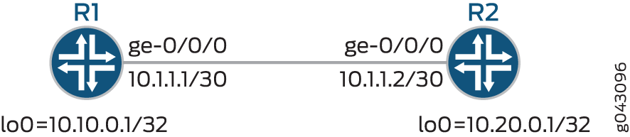
In this example, an associated bidirectional LSP is configured between Routers R1 and R2, for which the performance metrics is measured.
Configuration
CLI Quick Configuration
To quickly configure this example, copy the following commands, paste them into a
text file, remove any line breaks, change any details necessary to match your
network configuration, copy and paste the commands into the CLI at the
[edit] hierarchy level, and then enter
commit from configuration mode.
R1
set chassis fpc 0 pic 3 tunnel-services bandwidth 1g
set chassis network-services enhanced-ip
set interfaces ge-0/0/0 unit 0 family inet address 10.1.1.1/30
set interfaces ge-0/0/0 unit 0 family mpls
set interfaces lo0 unit 0 family inet address 10.10.0.1/32
set interfaces lo0 unit 0 family mpls
set routing-options router-id 10.10.0.1
set protocols rsvp interface ge-0/0/0.0
set protocols rsvp interface lo0.0
set protocols rsvp interface fxp0.0 disable
set protocols mpls statistics traffic-class-statistics
set protocols mpls label-switched-path R1-R2 to 10.20.0.1
set protocols mpls label-switched-path R1-R2 oam mpls-tp-mode
set protocols mpls label-switched-path R1-R2 ultimate-hop-popping
set protocols mpls label-switched-path R1-R2 associate-lsp R2-R1
set protocols mpls interface ge-0/0/0.0
set protocols mpls interface lo0.0
set protocols mpls interface fxp0.0 disable
set protocols ospf traffic-engineering
set protocols ospf area 0.0.0.0 interface ge-0/0/0.0
set protocols ospf area 0.0.0.0 interface lo0.0
set protocols ospf area 0.0.0.0 interface fxp0.0 disable
R2
set chassis fpc 0 pic 3 tunnel-services bandwidth 1g
set chassis network-services enhanced-ip
set interfaces ge-0/0/0 unit 0 family inet address 10.1.1.2/30
set interfaces ge-0/0/0 unit 0 family mpls
set interfaces lo0 unit 0 family inet address 10.20.0.1/32
set interfaces lo0 unit 0 family mpls
set routing-options router-id 10.20.0.1
set protocols rsvp interface ge-0/0/0.0
set protocols rsvp interface lo0.0
set protocols rsvp interface fxp0.0 disable
set protocols mpls statistics traffic-class-statistics
set protocols mpls label-switched-path R2-R1 to 10.10.0.1
set protocols mpls label-switched-path R2-R1 oam mpls-tp-mode
set protocols mpls label-switched-path R2-R1 ultimate-hop-popping
set protocols mpls label-switched-path R2-R1 associate-lsp R1-R2
set protocols mpls interface ge-0/0/0.0
set protocols mpls interface lo0.0
set protocols mpls interface fxp0.0 disable
set protocols ospf traffic-engineering
set protocols ospf area 0.0.0.0 interface ge-0/0/0.0
set protocols ospf area 0.0.0.0 interface lo0.0
set protocols ospf area 0.0.0.0.interface fxp0.0 disable
Procedure
Step-by-Step Procedure
The following example requires that you navigate various levels in the configuration hierarchy. For information about navigating the CLI, see Using the CLI Editor in Configuration Mode in the CLI User Guide.
To configure Router R1:
-
Enable the chassis with tunnel services and enhanced IP network services configuration.
[edit chassis]
user@R1# set fpc 0 pic 3 tunnel-services bandwidth 1g
user@R1# set network-services enhanced-ip
-
Configure the interfaces for Router R1.
[edit interfaces]
user@R1# set ge-0/0/0 unit 0 family inet address 10.1.1.1/30
user@R1# set ge-0/0/0 unit 0 family mpls
user@R1# set lo0 unit 0 family inet address 10.10.0.1/32
user@R1# set lo0 unit 0 family mpls
-
Configure the router ID for Router R1.
[edit routing-options]
user@R1# set router-id 10.10.0.1
-
Enable RSVP on all the interfaces of Router R1, excluding the management interface.
[edit protocols]
user@R1# set rsvp interface ge-0/0/0.0
user@R1# set rsvp interface lo0.0
user@R1# set rsvp interface fxp0.0 disable
-
Enable MPLS on all the interfaces of Router R1, excluding the management interface.
[edit protocols]
user@R1# set mpls interface ge-0/0/0.0
user@R1# set mpls interface lo0.0
user@R1# set mpls interface fxp0.0 disable
-
Configure an associated bidirectional LSP to Router R2.
[edit protocols]
user@R1# set mpls label-switched-path R1-R2 to 10.20.0.1
user@R1# set mpls label-switched-path R1-R2 oam mpls-tp-mode
user@R1# set mpls label-switched-path R1-R2 ultimate-hop-popping
user@R1# set mpls label-switched-path R1-R2 associate-lsp R2-R1
-
Create traffic classes for maintaining data traffic statistics per traffic class.
This enables traffic class scoped loss measurement.
[edit protocols]
user@R1# set mpls statistics traffic-class-statistics
-
Configure OSPF with traffic engineering capabilities, and enable OSPF on all the interfaces of Router R1, excluding the management interface.
[edit protocols]
user@R1# set ospf traffic-engineering
user@R1# set ospf area 0.0.0.0 interface ge-0/0/0.0
user@R1# set ospf area 0.0.0.0 interface lo0.0
user@R1# set ospf interface fxp0.0 disable
Results
From configuration mode, confirm your configuration by entering the show
chassis, show interfaces, show
routing-options, and show protocols commands. If
the output does not display the intended configuration, repeat the instructions
in this example to correct the configuration.
user@R1# show chassis
fpc 0 {
    pic 3 {
        tunnel-services {
            bandwidth 1g;
        }
    }
}
network-services enhanced-ip;
user@R1# show interfaces
ge-0/0/0 {
    unit 0 {
        family inet {
            address 1o.1.1.1/30;
        }
        family mpls;
    }
}
lo0 {
    unit 0 {
        family inet {
            address 10.10.0.1/32;
        }
        family mpls;
    }
}
user@R1# show routing-options
router-id 10.10.0.1;
user@R1# show protocols
rsvp {
    interface ge-0/0/0.0;
    interface lo0.0;
    interface fxp0.0 {
        disable;
    }
}
mpls {
    statistics {
        traffic-class-statistics;
    }
    label-switched-path R1-R2 {
        to 10.20.0.1;
        oam mpls-tp-mode;
        ultimate-hop-popping;
        associate-lsp R2-R1;
    }
    interface ge-0/0/0.0;
    interface lo0.0;
    interface fxp0.0 {
        disable;
    }
}
ospf {
    traffic-engineering;
    area 0.0.0.0 {
        interface ge-0/0/0.0;
        interface lo0.0;
        interface fxp0.0 {
            disable;
        }
    }
}
Verification
Confirm that the configuration is working properly.
- Verifying the LSP Status
- Verifying Packet Loss Measurement
- Verifying Packet Delay Measurement
- Verifying Packet Loss-Delay Measurement
Verifying the LSP Status
Purpose
Verify that the associated bidirectional LSP between Routers R1 and R2 is up.
Action
From operational mode, run the show mpls lsp command.
user@R1> show mpls lsp
Ingress LSP: 1 sessions
To              From            State Rt P     ActivePath       LSPname
10.20.0.1        10.10.0.1        Up     0 *                      R1-R2 Assoc-Bidir
Total 1 displayed, Up 1, Down 0

Egress LSP: 1 sessions
To              From            State   Rt Style Labelin Labelout LSPname
10.10.0.1        10.20.0.1        Up       0  1 FF  299776        - R2-R1 Assoc-Bidir
Total 1 displayed, Up 1, Down 0

Transit LSP: 0 sessions
Total 0 displayed, Up 0, Down 0
Use the show mpls lsp statistics command to display accounting and statistics information about LSP.
Meaning
The associated bidirectional LSP R1-R2 is up and active.
Verifying Packet Loss Measurement
Purpose
Verify the on-demand loss measurement result.
Action
From operational mode, run the monitor mpls loss rsvp R1-R2 count 2
detail command.
user@R1> monitor mpls loss rsvp R1-R2 count 2 detail
(0)
Response code                            : Success
Origin timestamp                         : 1404129082 secs, 905571890 nsecs
Forward transmit count                   : 83040
Forward receive count                    : 83040
Reverse transmit count                   : 83100
Reverse receive count                    : 83100
(1)
Response code                            : Success
Origin timestamp                         : 1404129083 secs, 905048410 nsecs
Forward transmit count                   : 83841
Forward receive count                    : 83841
Reverse transmit count                   : 83904
Reverse receive count                    : 83904
Current forward transmit count           : 801
Current forward receive count            : 801
Current forward loss                     : 0 packets
Current forward loss ratio               : 0.000000
Current forward throughput               : 0.801 kpps
Current reverse transmit count           : 804
Current reverse receive count            : 804
Current reverse loss                     : 0 packets
Current reverse loss ratio               : 0.000000
Current reverse throughput               : 0.804 kpps
(2)
Response code                            : Success
Origin timestamp                         : 1404129084 secs, 904828715 nsecs
Forward transmit count                   : 84423
Forward receive count                    : 84423
Reverse transmit count                   : 84487
Reverse receive count                    : 84487
Current forward transmit count           : 582
Current forward receive count            : 582
Current forward loss                     : 0 packets
Current forward loss ratio               : 0.000000
Current forward throughput               : 0.582 kpps
Current reverse transmit count           : 583
Current reverse receive count            : 583
Current reverse loss                     : 0 packets
Current reverse loss ratio               : 0.000000
Current reverse throughput               : 0.583 kpps

Cumulative forward transmit count        : 1383
Cumulative forward loss                  : 0 packets
Average forward loss ratio               : 0.000000
Average forward throughput               : 0.692 kpps
Cumulative reverse transmit count        : 1387
Cumulative reverse loss                  : 0 packets
Average reverse loss ratio               : 0.000000
Average reverse throughput               : 0.694 kpps

LM queries sent                          : 3
LM responses received                    : 3
LM queries timedout                      : 0
LM responses dropped due to errors       : 0
Meaning
The packet loss measurement for two counts is displayed.
Verifying Packet Delay Measurement
Purpose
Verify the on-demand delay measurement result.
Action
From operational mode, run the monitor mpls delay rsvp R1-R2 count 2
detail command.
user@R1> monitor mpls delay rsvp R1-R2 count 2 detail
(1)
Response code                            : Success
Querier transmit timestamp               : 1404129122 secs, 479955401 nsecs
Responder receive timestamp              : 1404129122 secs, 468519022 nsecs
Responder transmit timestamp             : 1404129122 secs, 470255123 nsecs
Querier receive timestamp                : 1404129122 secs, 481736403 nsecs
Current two-way channel delay            : 44 usecs
Current round-trip-time                  : 1781 usecs
(2)
Response code                            : Success
Querier transmit timestamp               : 1404129123 secs, 480926210 nsecs
Responder receive timestamp              : 1404129123 secs, 469488696 nsecs
Responder transmit timestamp             : 1404129123 secs, 471130706 nsecs
Querier receive timestamp                : 1404129123 secs, 482613911 nsecs
Current two-way channel delay            : 45 usecs
Current round-trip-time                  : 1687 usecs

Best two-way channel delay               : 44 usecs
Worst two-way channel delay              : 45 usecs
Average two-way channel delay            : 45 usecs
Best round-trip-time                     : 1687 usecs
Worst round-trip-time                    : 1781 usecs
Average round-trip-time                  : 1734 usecs
Average forward delay variation          : 1 usecs
Average reverse delay variation          : 1 usecs

DM queries sent                          : 2
DM responses received                    : 2
DM queries timedout                      : 0
DM responses dropped due to errors       : 0
Meaning
The packet delay measurement for two counts is displayed.
Verifying Packet Loss-Delay Measurement
Purpose
Verify the on-demand loss and delay measurement result.
Action
From operational mode, run the monitor mpls loss-delay rsvp R1-R2
count 2 detail command.
user@R1> monitor mpls loss-delay rsvp R1-R2 count 2 detail
(0)
Response code                            : Success
Forward transmit count                   : 142049
Forward receive count                    : 142049
Reverse transmit count                   : 142167
Reverse receive count                    : 142167
Querier transmit timestamp               : 1404129161 secs, 554422723 nsecs
Responder receive timestamp              : 1404129161 secs, 542877570 nsecs
Responder transmit timestamp             : 1404129161 secs, 546004545 nsecs
Querier receive timestamp                : 1404129161 secs, 557599327 nsecs
(1)
Response code                            : Success
Forward transmit count                   : 143049
Forward receive count                    : 143049
Reverse transmit count                   : 143168
Reverse receive count                    : 143168
Current forward transmit count           : 1000
Current forward receive count            : 1000
Current forward loss                     : 0 packets
Current forward loss ratio               : 0.000000
Current forward throughput               : 1.000 kpps
Current reverse transmit count           : 1001
Current reverse receive count            : 1001
Current reverse loss                     : 0 packets
Current reverse loss ratio               : 0.000000
Current reverse throughput               : 1.001 kpps
Querier transmit timestamp               : 1404129162 secs, 554465742 nsecs
Responder receive timestamp              : 1404129162 secs, 542919166 nsecs
Responder transmit timestamp             : 1404129162 secs, 545812736 nsecs
Querier receive timestamp                : 1404129162 secs, 557409175 nsecs
Current two-way channel delay            : 49 usecs
Current round-trip-time                  : 2943 usecs
(2)
Response code                            : Success
Forward transmit count                   : 143677
Forward receive count                    : 143677
Reverse transmit count                   : 143799
Reverse receive count                    : 143799
Current forward transmit count           : 628
Current forward receive count            : 628
Current forward loss                     : 0 packets
Current forward loss ratio               : 0.000000
Current forward throughput               : 0.627 kpps
Current reverse transmit count           : 631
Current reverse receive count            : 631
Current reverse loss                     : 0 packets
Current reverse loss ratio               : 0.000000
Current reverse throughput               : 0.630 kpps
Querier transmit timestamp               : 1404129163 secs, 556698575 nsecs
Responder receive timestamp              : 1404129163 secs, 545150128 nsecs
Responder transmit timestamp             : 1404129163 secs, 546918408 nsecs
Querier receive timestamp                : 1404129163 secs, 558515047 nsecs
Current two-way channel delay            : 48 usecs
Current round-trip-time                  : 1816 usecs

Cumulative forward transmit count        : 1628
Cumulative forward loss                  : 0 packets
Average forward loss ratio               : 0.000000
Average forward throughput               : 0.813 kpps
Cumulative reverse transmit count        : 1632
Cumulative reverse loss                  : 0 packets
Average reverse loss ratio               : 0.000000
Average reverse throughput               : 0.815 kpps

Best two-way channel delay               : 48 usecs
Worst two-way channel delay              : 49 usecs
Average two-way channel delay            : 49 usecs
Best round-trip-time                     : 1816 usecs
Worst round-trip-time                    : 3176 usecs
Average round-trip-time                  : 2645 usecs
Average forward delay variation          : 1 usecs
Average reverse delay variation          : 0 usecs

LDM queries sent                         : 3
LDM responses received                   : 3
LDM queries timedout                     : 0
LDM responses dropped due to errors      : 0
Meaning
The packet loss and delay measurement for two counts is displayed.
Example: Configuring Pro-active Loss and Delay Measurements for Bidirectional MPLS LSPs
This example shows how to configure pro-active loss and delay measurements for point-to-point ultimate-hop popping label-switched paths (LSPs) in MPLS networks to monitor network performance.
Requirements
This example uses the following hardware and software components:
-
Two MX Series 5G Universal Routing Platforms that contain MPC/MICs only
-
Junos OS Release 15.1 or later running on all the routers
Before you begin:
-
Configure the device interfaces.
-
Configure the autonomous system numbers and router IDs for the devices.
-
Configure the following protocols:
-
MPLS
-
OSPF
-
RSVP
-
Overview
Starting with Junos OS Release 15.1, a pro-active tool to monitor and measure packet loss, packet delay, or both for associated bidirectional MPLS ultimate-hop popping point-to-point label-switched paths (LSPs) is introduced.
This feature provides the following performance metrics:
-
Inter-packet delay variation (IPDV)
-
Loss measurement
-
Round-trip delay (RTT)
-
Throughput measurement
-
Two-way channel delay
This functionality provides real-time visibility into network performance, thereby facilitating network performance planning, troubleshooting, and evaluation.
Topology
Figure 3 illustrates the pro-active loss and delay measurements using a simple two-router topology.
In this example, an associated bidirectional LSP is configured between Routers R1 and R2, for which the performance metrics are measured.
Configuration
CLI Quick Configuration
To quickly configure this example, copy the following commands, paste them into a
text file, remove any line breaks, change any details necessary to match your
network configuration, copy and paste the commands into the CLI at the
[edit] hierarchy level, and then enter
commit from configuration mode.
R1
set chassis network-services enhanced-ip
set interfaces ge-0/0/0 unit 0 family inet address 10.1.1.1/30
set interfaces ge-0/0/0 unit 0 family mpls
set interfaces lo0 unit 0 family inet address 10.10.0.1/32
set interfaces lo0 unit 0 family mpls
set protocols mpls interface ge-0/0/0.0
set protocols mpls interface lo0.0
set protocols mpls interface fxp0.0 disable
set protocols mpls label-switched-path R1-R2 associate-lsp R2-R1
set protocols mpls label-switched-path R1-R2 install 10.20.0.0/24 active
set protocols mpls label-switched-path R1-R2 oam mpls-tp-mode
set protocols mpls label-switched-path R1-R2 oam performance-monitoring querier delay traffic-class tc-0 query-interval 1000
set protocols mpls label-switched-path R1-R2 oam performance-monitoring querier loss traffic-class none query-interval 1000
set protocols mpls label-switched-path R1-R2 oam performance-monitoring querier loss-delay traffic-class tc-0 query-interval 1000
set protocols mpls label-switched-path R1-R2 oam performance-monitoring responder delay min-query-interval 1000
set protocols mpls label-switched-path R1-R2 oam performance-monitoring responder loss min-query-interval 1000
set protocols mpls label-switched-path R1-R2 to 10.20.0.1
set protocols mpls label-switched-path R1-R2 ultimate-hop-popping
set protocols mpls statistics traffic-class-statistics
set protocols ospf area 0.0.0.0 interface ge-0/0/0.0
set protocols ospf area 0.0.0.0 interface lo0.0
set protocols ospf area 0.0.0.0 interface fxp0.0 disable
set protocols ospf traffic-engineering
set protocols rsvp interface ge-0/0/0.0
set protocols rsvp interface lo0.0
set protocols rsvp interface fxp0.0 disable
set routing-options router-id 10.10.0.1
R2
set chassis network-services enhanced-ip
set interfaces ge-0/0/0 unit 0 family inet address 10.1.1.2/30
set interfaces ge-0/0/0 unit 0 family mpls
set interfaces lo0 unit 0 family inet address 10.20.0.1/32
set interfaces lo0 unit 0 family mpls
set protocols mpls interface ge-0/0/0.0
set protocols mpls interface lo0.0
set protocols mpls interface fxp0.0 disable
set protocols mpls label-switched-path R2-R1 associate-lsp R1-R2
set protocols mpls label-switched-path R2-R1 install 10.10.0.0/24 active
set protocols mpls label-switched-path R2-R1 oam mpls-tp-mode
set protocols mpls label-switched-path R2-R1 oam performance-monitoring responder delay min-query-interval 1000
set protocols mpls label-switched-path R2-R1 oam performance-monitoring responder loss min-query-interval 1000
set protocols mpls label-switched-path R2-R1 oam performance-monitoring querier delay traffic-class tc-0 query-interval 1000
set protocols mpls label-switched-path R2-R1 oam performance-monitoring querier loss traffic-class none query-interval 1000
set protocols mpls label-switched-path R2-R1 oam performance-monitoring querier loss-delay traffic-class tc-0 query-interval 1000
set protocols mpls label-switched-path R2-R1 to 10.10.0.1
set protocols mpls label-switched-path R2-R1 ultimate-hop-popping
set protocols mpls statistics traffic-class-statistics
set protocols ospf area 0.0.0.0 interface ge-0/0/0.0
set protocols ospf area 0.0.0.0 interface lo0.0
set protocols ospf area 0.0.0.0 interface fxp0.0 disable
set protocols ospf traffic-engineering
set protocols rsvp interface ge-0/0/0.0
set protocols rsvp interface lo0.0
set protocols rsvp interface fxp0.0 disable
set routing-options router-id 10.20.0.1
Procedure
Step-by-Step Procedure
The following example requires that you navigate various levels in the configuration hierarchy. For information about navigating the CLI, see Using the CLI Editor in Configuration Mode in the CLI User Guide.
To configure Router R1:
-
Enable the enhanced IP network services configuration.
[edit chassis]
user@R1# set network-services enhanced-ip
-
Configure the interfaces for Router R1.
[edit interfaces]
user@R1# set ge-0/0/0 unit 0 family inet address 10.1.1.1/30
user@R1# set ge-0/0/0 unit 0 family mpls
user@R1# set lo0 unit 0 family inet address 10.10.0.1/32
user@R1# set lo0 unit 0 family mpls
-
Configure the router ID for Router R1.
[edit routing-options]
user@R1# set router-id 10.10.0.1
-
Enable RSVP on all the interfaces of Router R1, excluding the management interface.
[edit protocols]
user@R1# set rsvp interface ge-0/0/0.0
user@R1# set rsvp interface lo0.0
user@R1# set rsvp interface fxp0.0 disable
-
Enable MPLS on all the interfaces of Router R1, excluding the management interface.
[edit protocols]
user@R1# set mpls interface ge-0/0/0.0
user@R1# set mpls interface lo0.0
user@R1# set mpls interface fxp0.0 disable
-
Configure an associated bidirectional LSP to Router R2.
[edit protocols]
user@R1# set mpls label-switched-path R1-R2 to 10.20.0.1
user@R1# set mpls label-switched-path R1-R2 install 10.20.0.0/24 active
user@R1# set mpls label-switched-path R1-R2 oam mpls-tp-mode
user@R1# set mpls label-switched-path R1-R2 ultimate-hop-popping
user@R1# set mpls label-switched-path R1-R2 associate-lsp R2-R1
-
Create traffic classes for maintaining data traffic statistics per traffic class.
This enables traffic class scoped loss and delay measurement.
[edit protocols]
user@R1# set mpls statistics traffic-class-statistics
-
Configure performance monitoring at the querier side.
[edit protocols]
user@R1# set mpls label-switched-path R1-R2 oam performance-monitoring querier delay traffic-class tc-0 query-interval 1000
user@R1# set mpls label-switched-path R1-R2 oam performance-monitoring querier loss traffic-class none query-interval 1000
user@R1# set mpls label-switched-path R1-R2 oam performance-monitoring querier loss-delay traffic-class tc-0 query-interval 1000
-
Configure performance monitoring at the responder side.
[edit protocols]
user@R1# set mpls label-switched-path R1-R2 oam performance-monitoring responder delay min-query-interval 1000
user@R1# set mpls label-switched-path R1-R2 oam performance-monitoring responder loss min-query-interval 1000
-
Configure OSPF with traffic engineering capabilities, and enable OSPF on all the interfaces of Router R1, excluding the management interface.
[edit protocols]
user@R1# set ospf traffic-engineering
user@R1# set ospf area 0.0.0.0 interface ge-0/0/0.0
user@R1# set ospf area 0.0.0.0 interface lo0.0
user@R1# set ospf interface fxp0.0 disable
Results
From configuration mode, confirm your configuration by entering the show
chassis, show interfaces, show
routing-options, and show protocols commands. If
the output does not display the intended configuration, repeat the instructions
in this example to correct the configuration.
user@R1# show chassis
network-services enhanced-ip;
user@R1# show interfaces
ge-0/0/0 {
    unit 0 {
        family inet {
            address 10.1.1.1/30;
        }
        family mpls;
    }
}
lo0 {
    unit 0 {
        family inet {
            address 10.10.0.1/32;
        }
        family mpls;
    }
}
user@R1# show routing-options
router-id 10.10.0.1;
user@R1# show protocols
rsvp {
    interface ge-0/0/0.0;
    interface lo0.0;
    interface fxp0.0 {
        disable;
    }
}
mpls {
    label-switched-path R1-R2 {
        to 10.20.0.1;
        install 10.20.0.0/24  active;
        oam {
            mpls-tp-mode;
            performance-monitoring {
                querier {
                    loss {
                        traffic-class none {
                            query-interval 1000;
                        }
                    }
                    delay {
                        traffic-class tc-0 {
                            query-interval 1000;
                        }
                    }
                    loss-delay {
                        traffic-class none {
                            query-interval 1000;
                        }
                    }
                }
                responder {
                    loss {
                        min-query-interval 1000;
                    }
                    delay {
                        min-query-interval 1000;
                    }
                }
            }
        }
        ultimate-hop-popping;
        associate-lsp R2-R1;
    }
}
ospf {
    traffic-engineering;
    area 0.0.0.0 {
        interface ge-0/0/0.0;
        interface lo0.0;
        interface fxp0.0 {
            disable;
        }
    }
}
Verification
Verifying Loss and Delay Measurement
Purpose
Verify the loss and delay measurement.
Action
From operational mode, run the show performance-monitoring mpls
lsp command.
user@R1> show performance-monitoring mpls lsp
Session Total: 3 Up: 3 Down: 0
  LSP name:R1-R2, PM State:Up
    Loss measurement Data:
      Duration: 00:04:43
      Traffic-class: None
      Queries sent: 282
      Responses received: 282
      Responses dropped due to errors: 0
      Queries timeout: 0
      Forward loss measurement:
        Average packet loss: 0
        Average packet throughput: 554338
      Reverse loss measurement:
        Average packet loss: 0
        Average packet throughput: 1352077
  LSP name:R1-R2, PM State:Up
    Delay measurement Data:
      Duration: 00:04:43
      Traffic-class: 0
      Queries sent: 282
      Responses received: 282
      Responses dropped due to errors: 0
      Queries timeout: 0
      Best 2-way channel delay: 72 usecs
      Worst 2-way channel delay: 365 usecs
      Best round trip time: 843 usecs
      Worst round trip time: 105523 usecs
      Avg absolute fw delay variation: 1619 usecs
      Avg absolute rv delay variation: 1619 usecs
  LSP name:R1-R2, PM State:Up
    Loss measurement Data:
      Duration: 00:04:43
      Traffic-class: None
      Queries sent: 282
      Responses received: 282
      Responses dropped due to errors: 0
      Queries timeout: 0
      Forward loss measurement:
        Average packet loss: 0
        Average packet throughput: 553927
      Reverse loss measurement:
        Average packet loss: 0
        Average packet throughput: 1351531
    Delay measurement Data:
      Best 2-way channel delay: 76 usecs
      Worst 2-way channel delay: 368 usecs
      Best round trip time: 1082 usecs
      Worst round trip time: 126146 usecs
      Avg absolute fw delay variation: 1618 usecs
      Avg absolute rv delay variation: 1619 usecs
Meaning
The packet loss and delay measurement metrics for LSP are displayed.
Configuring On-Demand Loss and Delay Measurement
You can configure an on-demand loss and delay measurement
for point-to-point ultimate hop popping (UHP) label-switched paths
(LSPs) in MPLS networks to monitor network performance. The monitor
mpls loss rsvp, monitor mpls delay rsvp, and monitor mpls loss-delay rsvp CLI commands provide an on-demand
summary of performance metrics for direct mode packet loss, two-way
packet delay, and related metrics, such as inter-packet delay variation
and channel throughput measurement.
This functionality provides real-time visibility into network performance, thereby facilitating network performance planning, troubleshooting, and evaluation.
Before you begin:
Configure the device interfaces.
Configure the device router ID.
Configure the following protocols:
RSVP
OSPF
Enable traffic engineering capabilities.
MPLS
To configure the PE device:
Configuring Pro-Active Loss and Delay Measurements
You can configure pro-active loss and delay measurements
for point-to-point ultimate-hop popping label-switched paths (LSPs)
in MPLS networks to monitor network performance. The show performance-monitoring
mpls lsp CLI command provides a summary of performance metrics
for direct mode packet loss, two-way packet delay, and related metrics,
such as inter-packet delay variation and channel throughput measurement.
This functionality provides real-time visibility into network performance, thereby facilitating network performance planning, troubleshooting, and evaluation.
This feature provides the following performance metrics:
Inter-packet delay variation (IPDV)
Loss measurement
Round-trip delay (RTT)
Throughput measurement
Two-way channel delay
Before you begin:
Configure the device interfaces.
Configure the autonomous system numbers and router IDs for the devices.
Configure the following protocols:
MPLS
OSPF
RSVP
To configure pro-active loss and delay measurements on the PE device: