ON THIS PAGE
MPLS Pseudowires Configuration
Ethernet Pseudowire Overview
Starting in Junos OS Release 14.1X53 and Junos OS Release 16.1, an Ethernet pseudowire is used to carry Ethernet or 802.3 Protocol Data Units (PDUs) over an MPLS network enabling service providers to offer emulated Ethernet services over existing MPLS networks. Ethernet or 802.3 PDUs are encapsulated within the pseudowire to provide a point-to-point Ethernet service. For the point-to-point Ethernet service, the following fault management features are supported:
The IEEE 802.3ah standard for Operation, Administration, and Management (OAM). You can configure IEEE 802.3ah OAM link-fault management on Ethernet point-to-point direct links or links across Ethernet repeaters.
Ethernet OAM link-fault management can be used for physical link-level fault detection and management. It uses a new, optional sublayer in the data link layer of the OSI model. Ethernet OAM can be implemented on any full-duplex point-to-point or emulated point-to-point Ethernet link. A system-wide implementation is not required; OAM can be deployed on particular interfaces of a router. Transmitted Ethernet OAM messages or OAM PDUs are of standard length, untagged Ethernet frames within the normal frame length limits in the range 64–1518 bytes.
Ethernet connectivity fault management (CFM) to monitor the physical link between two routers.
Connection protection using the continuity check protocol for fault monitoring . The continuity check protocol is a neighbor discovery and health check protocol that discovers and maintains adjacencies at the VLAN or link level.
Path protection using the linktrace protocol for path discovery and fault verification . Similar to IP traceroute, the linktrace protocol maps the path taken to a destination MAC address through one or more bridged networks between the source and destination.
Example: Ethernet Pseudowire Base Configuration
- Requirements
- Overview of an Ethernet Pseudowire Base Configuration
- Configuring an Ethernet Pseudowire
Requirements
The following is a list of the hardware and software requirements for this configuration.
One ACX Series router
Junos OS Release 12.2 or later
Overview of an Ethernet Pseudowire Base Configuration
The configuration shown here is the base configuration of an Ethernet pseudowire with Ethernet cross-connect for physical interface encapsulation on an ACX Series router. This configuration is for one provider edge router. To complete the configuration of an Ethernet pseudowire, you need to repeat this configuration on an other provider edge router in the Multiprotocol Label Switched (MPLS) network.
Configuring an Ethernet Pseudowire
Procedure
CLI Quick Configuration
To quickly configure this example, copy the
following commands, paste them in a text file, remove any line breaks,
change any details necessary to match your network configuration,
and then copy and paste the commands into the CLI at the [edit] hierarchy level:
set interfaces ge-0/1/1 encapsulation ethernet-ccc
set interfaces ge-0/1/1 unit 0
set interfaces ge-0/2/0 unit 0 family inet address 20.1.1.2/24
set interfaces ge-0/2/0 unit 0 family mpls
set interfaces lo0 unit 0 family inet address 70.1.1.1/32
set protocols rsvp interface ge-0/2/0.0
set protocols mpls no-cspf
set protocols mpls label-switched-path PE1-to-PE2 to 40.1.1.1
set protocols mpls interface ge-0/2/0.0
set protocols ospf traffic-engineering
set protocols ospf area 0.0.0.0 interface ge-0/2/0.0
set protocols ospf area 0.0.0.0 interface lo0.0 passive
set protocols ldp interface ge-0/2/0.0
set protocols ldp interface lo0.0
set protocols l2circuit neighbor 40.1.1.1 interface ge-0/1/1.0 virtual-circuit-id 1
To configure an Ethernet pseudowire with 802.1Q tagging
for cross-connect logical interface encapsulation, include the vlan-ccc statement at the [edit interfaces ge-0/1/1 unit
0 encapsulation] hierarchy level instead of the ethernet-ccc statement shown in this example.
Step-by-Step Procedure
Create two Gigabit Ethernet interfaces, set the encapsulation mode on one interface and MPLS on the other interface. Create the loopback (
lo0) interface:[edit] user@host# edit interfaces [edit interfaces] user@host# set ge-0/1/1 encapsulation ethernet-ccc user@host# set ge-0/1/1 unit 0 user@host# set ge-0/2/0 unit 0 family inet address 20.1.1.2/24 user@host# set ge-0/2/0 unit 0 family mpls user@host# set lo0 unit 0 family inet address 70.1.1.1/32
Enable the MPLS and RSVP protocols on the interface configured with MPLS—
ge-0/2/0.0:[edit] user@host# edit protocols [edit protocols] user@host# set rsvp interface ge-0/2/0.0 user@host# set mpls interface ge-0/2/0.0
Configure LDP. If you configure RSVP for a pseudowire, you must also configure LDP:
[edit protocols]
user@host# set protocols ldp interface ge-0/2/0.0
user@host# set protocols ldp interface lo0.0
Configure a point-to-point label-switched path (LSP) and disable constrained-path LSP computation:
[edit protocols]
user@host# set mpls label-switched-path PE1-to-PE2 to 40.1.1.1
user@host# set mpls no-cspf
Configure OSPF and enable traffic engineering on the MPLS interface—
ge-0/2/0.0, and on the loopback (lo0) interface:[edit protocols] user@host# set ospf traffic-engineering user@host# set ospf area 0.0.0.0 interface ge-0/2/0.0 user@host# set ospf area 0.0.0.0 interface lo0.0 passive
Uniquely identify a Layer 2 circuit for the Ethernet pseudowire:
[edit protocols]
user@host#  set l2circuit neighbor 40.1.1.1 interface ge-0/1/1.0 virtual-circuit-id 1
Results
[edit]
user@host# show
interfaces {
    ge-0/1/1 {
        encapsulation ethernet-ccc;
        unit 0;
    }
    ge-0/2/0 {
        unit 0 {
            family inet {
                address 20.1.1.2/24;
            }
            family mpls;
        }
    }
    lo0 {
        unit 0 {
            family inet {
                address 70.1.1.1/32;
            }
        }
    }
}
protocols {
    rsvp {
        interface ge-0/2/0.0;
    }
    mpls {
        no-cspf;
        label-switched-path PE1-to-PE2 {
            to 40.1.1.1;
        }
        interface ge-0/2/0.0;
    }
    ospf {
        traffic-engineering;
        area 0.0.0.0 {
            interface ge-0/2/0.0;
            interface lo0.0 {
                passive;
            }
        }
    }
    ldp {
        interface ge-0/2/0.0;
        interface lo0.0;
    }
    l2circuit {
        neighbor 40.1.1.1 {
            interface ge-0/1/1.0 {
                virtual-circuit-id 1;
            }
        }
    }
}
Pseudowire Overview for ACX Series Universal Metro Routers
A pseudowire is a Layer 2 circuit or service, which emulates the essential attributes of a telecommunications service— such as a T1 line, over an MPLS packet-switched network. The pseudowire is intended to provide only the minimum necessary functionality to emulate the wire with the required degree of faithfulness for the given service definition. On the ACX Series routers, Ethernet, Asynchronous Transfer Mode (ATM), and time-division multiplexing (TDM) pseudowires are supported. The following pseudowire features are supported:
Pseudowire transport service carrying Layer 1 and Layer 2 information over an IP and MPLS network infrastructure. Only similar end points are supported on the ACX Series—for example, T1 to T1, ATM to ATM, and Ethernet to Ethernet.
Redundant pseudowires backup connections between PE routers and CE devices, maintaining Layer 2 circuits and services after certain types of failures. Pseudowire redundancy improves the reliability of certain types of networks (metro for example) where a single point of failure could interrupt service for multiple customers. The following pseudowire redundancy features are supported:
Maintenance of Layer 2 circuit services after certain types of failures with a standby pseudowire, which backs up the connection between PE routers and CE devices.
In case of failure, a protect interface, which backs up the primary interface. Network traffic uses the primary interface only so long as the primary interface functions. If the primary interface fails, traffic is switched to the protect interface.
Hot and cold standby enabling swift cut over to the backup or standby pseudowire.
Ethernet connectivity fault management (CFM), which can be used to monitor the physical link between two routers. The following major features of CFM for Ethernet pseudowires only are supported:
Connection protection using the continuity check protocol for fault monitoring. The continuity check protocol is a neighbor discovery and health check protocol that discovers and maintains adjacencies at the VLAN or link level.
Path protection using the linktrace protocol for path discovery and fault verification. Similar to IP traceroute, the linktrace protocol maps the path taken to a destination MAC address through one or more bridged networks between the source and destination.
Understanding Multisegment Pseudowire for FEC 129
- Understanding Multisegment Pseudowire
- Using FEC 129 for Multisegment Pseudowire
- Establishing a Multisegment Pseudowire Overview
- Pseudowire Status Support for Multisegment Pseudowire
- Pseudowire TLV Support for MS-PW
- Supported and Unsupported Features
Understanding Multisegment Pseudowire
A pseudowire is a Layer 2 circuit or service that emulates the essential attributes of a telecommunications service, such as a T1 line, over an MPLS packet-switched network (PSN). The pseudowire is intended to provide only the minimum necessary functionality to emulate the wire with the required resiliency requirements for the given service definition.
When a pseudowire originates and terminates on the edge of the same PSN, the pseudowire label is unchanged between the originating and terminating provider edge (T-PE) devices. This is called a single-segment pseudowire (SS-PW). Figure 1 illustrates an SS-PW established between two PE routers. The pseudowires between the PE1 and PE2 routers are located within the same autonomous system (AS).
In cases where it is impossible to establish a single pseudowire from a local to a remote PE, either because it is unfeasible or undesirable to establish a single control plane between the two PEs, a multisegment pseudowire (MS-PW) is used.
An MS-PW is a set of two or more contiguous SS-PWs that are made to function as a single point-to-point pseudowire. It is also known as switched pseudowire. MS-PWs can go across different regions or network domains. A region can be considered as an interior gateway protocol (IGP) area or a BGP autonomous system that belongs to the same or different administrative domain. An MS-PW spans multiple cores or ASs of the same or different carrier networks. A Layer 2 VPN MS-PW can include up to 254 pseudowire segments.
Figure 2 illustrates a set of two or more pseudowire segments that function as a single pseudowire. The end routers are called terminating PE (T-PE) routers, and the switching routers are called switching PE (S-PE) routers. The S-PE router terminates the tunnels of the preceding and succeeding pseudowire segments in an MS-PW. The S-PE router can switch the control and data planes of the preceding and succeeding pseudowire segments of the MS-PW. An MS-PW is declared to be up when all the single-segment pseudowires are up.
Using FEC 129 for Multisegment Pseudowire
Currently, there are two types of attachment circuit identifiers (AIIs) defined under FEC 129:
Type 1 AII
Type 2 AII
The support of an MS-PW for FEC 129 uses type 2 AII. A type 2 AII is globally unique by definition of RFC 5003.
Single-segment pseudowires (SS-PWs) using FEC 129 on an MPLS PSN can use both type 1 and type 2 AII. For an MS-PW using FEC 129, a pseudowire itself is identified as a pair of endpoints. This requires that the pseudowire endpoints be uniquely identified.
In the case of a dynamically placed MS-PW, there is a requirement for the identifiers of attachment circuits to be globally unique, for the purposes of reachability and manageability of the pseudowire. Thus, individual globally unique addresses are allocated to all the attachment circuits and S-PEs that make up an MS-PW.
Type 2 AII is composed of three fields:
Global_ID—Global identification, which is usually the AS number.
Prefix—IPv4 address, which is usually the router ID.
AC_ID—Local attachment circuit, which is a user-configurable value.
Since type 2 AII already contains the T-PE's IP address and it is globally unique, from the FEC 129 pseudowire signaling point of view, the combination (AGI, SAII, TAII) uniquely identifies an MS-PW across all interconnected pseudowire domains.
Establishing a Multisegment Pseudowire Overview
An MS-PW is established by dynamically and automatically selecting the predefined S-PEs and placing the MS-PW between two T-PE devices.
When S-PEs are dynamically selected, each S-PE is automatically discovered and selected using the BGP autodiscovery feature, without the requirement of provisioning the FEC 129 pseudowire-related information on all the S-PEs. BGP is used to propagate pseudowire address information throughout the PSN.
Since there is no manual provisioning of FEC 129 pseudowire information on the S-PEs, the Attachment Group Identifier (AGI) and Attachment Individual Identifier (AII) are reused automatically, and choosing the same set of S-PEs for the pseudowire in both the forwarding and reverse direction is achieved through the active and passive role of each T-PE device.
Active—The T-PE initiates an LDP label mapping message.
Passive—The T-PE does not initiate an LDP label mapping message until it receives a label mapping message initiated by the active T-PE. The passive T-PE sends its label mapping message to the same S-PE from where it received the label mapping message originated from its active T-PE. This ensures that the same set of S-PEs are used in the reverse direction.
Pseudowire Status Support for Multisegment Pseudowire
Pseudowire Status Behavior on T-PE
The following pseudowire status messages are relevant on the T-PE:
0x00000010—Local PSN-facing pseudowire (egress) transmit fault.
0x00000001—Generic nonforwarding fault code. This is set as the local fault code. The local fault code is set at the local T-PE, and LDP sends a pseudowire status TLV message with the same fault code to the remote T-PE.
Fault codes are bit-wise OR’ed and stored as remote pseudowire status codes.
Pseudowire Status Behavior on S-PE
The S-PE initiates the pseudowire status messages that indicate the pseudowire faults. The SP-PE in the pseudowire notification message hints where the fault was originated.
When a local fault is detected by the S-PE, a pseudowire status message is sent in both directions along the pseudowire. Since there are no attachment circuits on an S-PE, only the following status messages are relevant:
0x00000008—Local PSN-facing pseudowire (ingress) receive fault.
0x00000010—Local PSN-facing pseudowire (egress) transmit fault.
To indicate which SS-PW is at fault, an LDP SP-PE TLV is attached with the pseudowire status code in the LDP notification message. The pseudowire status is passed along from one pseudowire to another unchanged by the control plane switching function.
If an S-PE initiates a pseudowire status notification message with one particular pseudowire status bit, then for the pseudowire status code an S-PE receives, the same bit is processed locally and not forwarded until the S-PE's original status error is cleared.
An S-PE keeps only two pseudowire status codes for each SS-PW it is involved in – local pseudowire status code and remote pseudowire status code. The value of the remote pseudowire status code is the result of logic or operation of the pseudowire status codes in the chain of SS-PWs preceding this segment. This status code is incrementally updated by each S-PE upon receipt and communicated to the next S-PE. The local pseudowire status is generated locally based on its local pseudowire status.
Only transmit fault is detected at the SP-PE. When there is no MPLS LSP to reach the next segment, a local transmit fault is detected. The transmit fault is sent to the next downstream segment, and the receive fault is sent to the upstream segment.
Remote failures received on an S-PE are just passed along the MS-PW unchanged. Local failures are sent to both segments of the pseudowire that the S-PE is involved in.
Pseudowire TLV Support for MS-PW
MS-PW provides the following support for the LDP SP-PE TLV [RFC 6073]:
The LDP SP-PE TLVs for an MS-PW include:
Local IP address
Remote IP address
An SP-PE adds the LDP SP-PE TLV to the label mapping message. Each SP-PE appends the local LDP SP-PE TLV to the SP-PE list it received from the other segment.
The pseudowire status notification message includes the LDP SP-PE TLV when the notification is generated at the SP-PE.
Supported and Unsupported Features
Junos OS supports the following features with MS-PW:
MPLS PSN for each SS-PW that builds up the MS-PW.
The same pseudowire encapsulation for each SS-PW in an MS-PW – Ethernet or VLAN-CCC.
The generalized PWid FEC with T-LDP as an end-to-end pseudowire signaling protocol to set up each SS-PW.
MP-BGP to autodiscover the two endpoint PEs for each SS-PW associated with the MS-PW.
Standard MPLS operation to stitch two side-by-side SS-PWs to form an MS-PW.
Automatic discovery of S-PE so that the MS-PW can be dynamically placed.
Minimum provisioning of S-PE.
Operation, administration, and maintenance (OAM) mechanisms, including end-to-end MPLS ping or end-to-any-S-PE MPLS ping, MPLS path trace, end-to-end VCCV, and Bidirectional Forwarding Detection (BFD).
Pseudowire swithing point (SP) PE TLV for the MS-PW.
Composite next hop on MS-PW.
Pseudowire status TLV for MS-PW.
Junos OS does not support the following MS-PW functionality:
Mix of LDP FEC 128 and LDP FEC 129.
Static pseudowire where each label is provisioned staticially.
Graceful Routing Engine switchover.
Nonstop active routing.
Multihoming.
Partial connectivity verification (originating from an S-PE) in OAM.
Example: Configuring a Multisegment Pseudowire
This example shows how to configure a dynamic multisegment pseudowire (MS-PW), where the stitching provider edge (S-PE) devices are automatically and dynamically discovered by BGP, and pseudowires are signaled by LDP using FEC 129. This arrangement requires minimum provisioning on the S-PEs, thereby reducing the configuration burden that is associated with statically configured Layer 2 circuits while still using LDP as the underlying signaling protocol.
Requirements
This example uses the following hardware and software components:
Six routers that can be a combination of M Series Multiservice Edge Routers, MX Series 5G Universal Routing Platforms, T Series Core Routers, or PTX Series Packet Transport Routers.
Two remote PE devices configured as terminating PEs (T-PEs).
Two S-PEs configured as:
Route reflectors, in the case of interarea configuration.
AS boundary routers or route reflectors, in the case of inter-AS configuration.
Junos OS Release 13.3 or later running on all the devices.
Before you begin:
Configure the device interfaces.
Configure OSPF or any other IGP protocol.
Configure BGP.
Configure LDP.
Configure MPLS.
Overview
Starting with Junos OS Release 13.3, you can configure an MS-PW using FEC 129 with LDP signaling and BGP autodiscovery in an MPLS packet-switched network (PSN). The MS-PW feature also provides operation, administration, and management (OAM) capabilities, such as ping, traceroute, and BFD, from the T-PE devices.
To enable autodiscovery of S-PEs in an MS-PW, include the auto-discovery-mspw statement at the [edit protocols bgp
group group-name family l2vpn] hierarchy
level.
family l2vpn {
    auto-discovery-mspw;
}
The automatic selection of S-PE and dynamic setting up of an
MS-PW rely heavily on BGP. BGP network layer reachability information
(NLRI) constructed for the FEC 129 pseudowire to autodiscover the
S-PE is called an MS-PW NLRI [draft-ietf-pwe3-dynamic-ms-pw-15.txt].
The MS-PW NLRI is essentially a prefix consisting of a route distinguisher
(RD) and FEC 129 source attachment identifier (SAII). It is referred
to as a BGP autodiscovery (BGP-AD) route and is encoded as RD:SAII.
Only T-PEs that are provisioned with type 2 AIIs initiate their own MS-PW NLRI respectively. Since a type 2 AII is globally unique, an MS-PW NLRI is used to identify a PE device to which the type 2 AII is provisioned. The difference between a type 1 AII and a type 2 AII requires that a new address family indicator (AFI) and subsequent address family identifier (SAFI) be defined in BGP to support an MS-PW. The proposed AFI and SAFI value pair used to identify the MS-PW NLRI is 25 and 6, respectively (pending IANA allocation).
The AFI and SAFI values support autodiscovery of S-PEs and should be configured on both T-PEs that originate the routes, and the S-PEs that participate in the signaling.
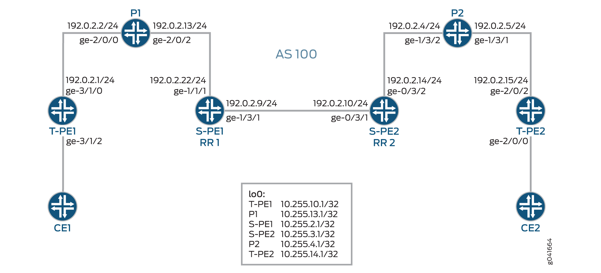
Figure 3 illustrates an inter-area MS-PW setup between two remote PE routers—T-PE1 and T-PE2. The Provider (P) routers are P1 and P2, and the S-PE routers are S-PE1 and S-PE2. The MS-PW is established between T-PE1 and T-PE2, and all the devices belong to the same AS—AS 100. Since S-PE1 and S-PE2 belong to the same AS, they act as route reflectors and are also known as RR 1 and RR 2, respectively.
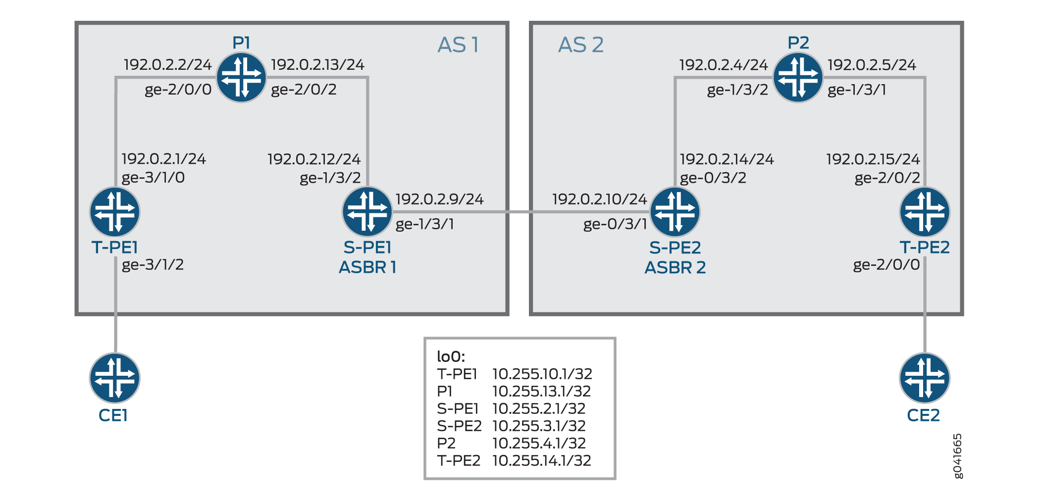
Figure 4 illustrates an inter-AS MS-PW setup. The MS-PW is established between T-PE1 and T-PE2, where T-PE1, P1, and S-PE1 belong to AS 1, and S-PE2, P2, and T-PE2 belong to AS 2. Since S-PE1 and S-PE2 belong to different ASs, they are configured as ASBR routers and are also known as ASBR 1 and ASBR 2, respectively.
The following sections provide information about how an MS-PW is established in an interarea and inter-AS scenario.
Minimum Configuration Requirements on S-PE
In order to dynamically discover both ends of an SS-PW and set up a T-LDP session dynamically, the following is required:
For interarea MS-PW, each S-PE plays both an ABR and BGP route reflector role.
In the interarea case, as seen in Figure 3, the S-PE plays a BGP route reflector role and reflects the BGP-AD route to its client. A BGP-AD route advertised by one T-PE eventually reaches its remote T-PE. Because of the next-hop-self set by each S-PE, the S-PE or T-PE that receives a BGP-AD route can always discover the S-PE that advertises the BGP-AD in its local AS or local area through the BGP next hop.
For inter-AS MS-PW, each S-PE plays either an ASBR or a BGP route reflector role.
In an MS-PW, the two T-PEs initiate a BGP-AD route respectively. When the S-PE receives the BGP-AD route through either the IBGP session with the T-PE or through a regular BGP-RR, it sets the next-hop-self before re-advertising the BGP-AD route to one or more of its EBGP peers in the inter-AS case, as seen in Figure 4.
Each S-PE must set next-hop-self when re-advertising or reflecting a BGP-AD route for the MS-PW.
Active and Passive Role of T-PE
To ensure that the same set of S-PEs are being used for a MS-PW in both directions, the two T-PEs play different roles in terms of FEC 129 signaling. This is to avoid different paths being chosen by T-PE1 and T-PE2 when each S-PE is dynamically selected for an MS-PW.
When an MS-PW is signaled using FEC 129, each T-PE might independently start signaling the MS-PW. The signaling procedure can result in an attempt to set up each direction of the MS-PW through different S-PEs.
To avoid this situation, one of the T-PEs must start the pseudowire signaling (active role), while the other waits to receive the LDP label mapping before sending the respective pseudowire LDP label mapping message (passive role). When the MS-PW path is dynamically placed, the active T-PE (the Source T-PE) and the passive T-PE (the Target T-PE) must be identified before signaling is initiated for a given MS-PW. The determination of which T-PE assumes the active role is done based on the SAII value, where the T-PE that has a larger SAII value plays the active role.
In this example, the SAII values of T-PE1 and T-PE 2 are 800:800:800 and 700:700:700, respectively. Since
T-PE1 has a higher SAII value, it assumes the active role and T-PE2
assumes the passive role.
Directions for Establishing an MS-PW
The directions used by the S-PE for setting up the MS-PW are:
Forwarding direction—From an active T-PE to a passive T-PE.
In this direction, the S-PEs perform a BGP-AD route lookup to determine the next-hop S-PE to send the label mapping message.
Reverse direction—From a passive T-PE to an active T-PE.
In this direction, the S-PEs do not perform a BGP-AD route lookup, because the label mapping messages are received from the T-PEs, and the stitching routes are installed in the S-PEs.
In this example, the MS-PW is established in the forwarding direction from T-PE1 to T-PE2. When the MS-PW is placed from T-PE2 to T-PE1, the MS-PW is established in the reverse direction.
Autodiscovery and Dynamic Selection of S-PE
A new AFI and SAFI value is defined in BGP to support the MS-PWs based on type 2 AII. This new address family supports autodiscovery of S-PEs. This address family must be configured on both the TPEs and SPEs.
It is the responsibility of the Layer 2 VPN component to dynamically select the next S-PE to use along the MS-PW in the forwarding direction.
In the forwarding direction, the selection of the next S-PE is based on the BGP-AD route advertised by the BGP and pseudowire FEC information sent by the LDP. The BGP-AD route is initiated by the passive T-PE (T-PE2) in the reverse direction while the pseudowire FEC information is sent by LDP from the active T-PE (T-PE1) in the forwarding direction.
In the reverse direction, the next S-PE (S-PE2) or the active T-PE (T-PE1) is obtained by looking up the S-PE (S-PE1) that it used to set up the pseudowire in the forwarding direction.
Provisioning a T-PE
To support FEC 129 type 2 AII, the T-PE needs to configure its remote T-PE's IP address, a global ID, and an attachment circuit ID. Explicit paths where a set of S-PEs to use is explicitly specified on a T-PE is not supported. This eliminates the need to provision each S-PE with a type 2 AII.
Stitching an MS-PW
An S-PE performs the following MPLS label operations before forwarding the received label mapping message to the next S-PE:
Pops the MPLS tunnel label.
Pops the VC label.
Pushes a new VC label.
Pushes an MPLS tunnel label used for the next segment.
Establishing an MS-PW
After completing the necessary configuration, an MS-PW is established in the following manner:
The SAII values are exchanged between T-PE1 and T-PE2 using BGP.
T-PE1 assumes the active T-PE role, because it is configured with a higher SAII value. T-PE2 becomes the passive T-PE.
T-PE1 receives the BGP-AD route originated by T-PE2. It compares the AII values obtained from T-PE2 in the received BGP-AD route against the AII values provisioned locally.
If the AII values match, T-PE1 performs a BGP-AD route lookup to elect the first S-PE (S-PE1).
T-PE1 sends an LDP label mapping message to S-PE1.
Using the BGP-AD route originated from T-PE2, and the LDP label mapping message received from T-PE1, S-PE1 selects the next S-PE (S-PE2) in the forwarding direction.
To do this, S-PE1 compares SAII obtained from the BGP-AD route against the TAI from the LDP label mapping message.
If the AII values match, S-PE1 finds S-PE2 through the BGP next hop associated with the BGP-AD route.
The process of selecting S-PE goes on until the last S-PE establishes a T-LDP session with T-PE2. When T-PE2 receives the LDP label mapping message from the last S-PE (S-PE2), it initiates its own label mapping message and sends it back to S-PE2.
When all the label mapping messages are received on S-PE1 and S-PE2, the S-PEs install the stitching routes. Thus, when the MS-PW is established in the reverse direction, the S-PEs need not perform BGP-AD route lookup to determine its next hop as it did in the forwarding direction.
OAM Support for an MS-PW
After the MS-PW is established, the following OAM capabilities can be executed from the T-PE devices:
Ping
End-to-End Connectivity Verification Between T-PEs
If T-PE1, S-PEs, and T-PE2 support Control Word (CW), the pseudowire control plane automatically negotiates the use of the CW. Virtual Circuit Connectivity Verification (VCCV) Control Channel (CC) Type 3 will function correctly whether or not the CW is enabled on the pseudowire. However, VCCV Type 1, which is used for end-to-end verification only, is only supported if the CW is enabled.
The following is a sample:
Ping from T-P1 to T-PE2
user@T-PE1> ping mpls l2vpn fec129 instance instance-name local-id SAII of T-PE1 remote-pe-address address of T-PE2 remote-id TAII of T-PE2
or
user@T-PE1> ping mpls l2vpn fec129 interface CE1-facing interface
Partial Connectivity Verification from T-PE to Any S-PE
To trace part of an MS-PW, the TTL of the pseudowire label can be used to force the VCCV message to pop out at an intermediate node. When the TTL expires, the S-PE can determine that the packet is a VCCV packet either by checking the CW or by checking for a valid IP header with UDP destination port 3502 (if the CW is not in use). The packet should then be diverted to VCCV processing.
If T-PE1 sends a VCCV message with the TTL of the pseudowire label equal to 1, the TTL expires at the S-PE. T-PE1 can thus verify the first segment of the pseudowire.
The VCCV packet is built according to RFC 4379. All the information necessary to build the VCCV LSP ping packet is collected by inspecting the S-PE TLVs. This use of the TTL is subject to the caution expressed in RFC 5085. If a penultimate LSR between S-PEs or between an S-PE and a T-PE manipulates the pseudowire label TTL, the VCCV message might not emerge from the MS-PW at the correct S-PE.
The following is a sample:
Ping from T-PE1 to S-PE
user@T-PE1> ping mpls l2vpn fec129 interface CE1-facing interface bottom-label-ttl segment
The
bottom-label-ttlvalue is 1 for S-PE1 and 2 for S-PE2.The
bottom-label-ttlstatement sets the correct VC label TTL, so the packets are popped to the correct SS-PW for VCCV processing.
Note:Junos OS supports VCCV Type 1 and Type 3 for the MS-PW OAM capability. VCCV Type 2 is not supported.
Traceroute
Traceroute tests each S-PE along the path of the MS-PW in a single operation similar to LSP trace. This operation is able to determine the actual data path of the MS-PW, and is used for dynamically signaled MS-PWs.
user@T-PE1> traceroute mpls l2vpn fec129 interface CE1-facing interface
Bidirectional Forwarding Detection
Bidirectional Forwarding Detection (BFD) is a detection protocol designed to provide fast forwarding path failure detection times for all media types, encapsulations, topologies, and routing protocols. In addition to fast forwarding path failure detection, BFD provides a consistent failure detection method for network administrators. The router or switch can be configured to log a system log (syslog) message when BFD goes down.
user@T-PE1> show bfd session extensive
Configuration
Configuring an Interarea MS-PW
CLI Quick Configuration
To quickly configure this example, copy the
following commands, paste them into a text file, remove any line breaks,
change any details necessary to match your network configuration,
and then copy and paste the commands into the CLI at the [edit] hierarchy level.
T-PE1
set interfaces ge-3/1/0 unit 0 family inet address 192.0.2.1/24
set interfaces ge-3/1/0 unit 0 family mpls
set interfaces ge-3/1/2 encapsulation ethernet-ccc
set interfaces ge-3/1/2 unit 0
set interfaces lo0 unit 0 family inet address 10.255.10.1/32 primary
set routing-options autonomous-system 100
set protocols mpls interface all
set protocols mpls interface fxp0.0 disable
set protocols bgp family l2vpn auto-discovery-mspw
set protocols bgp group mspw type internal
set protocols bgp group mspw local-address 10.255.10.1
set protocols bgp group mspw neighbor 10.255.2.1
set protocols ospf area 0.0.0.0 interface lo0.0
set protocols ospf area 0.0.0.0 interface all
set protocols ospf area 0.0.0.0 interface fxp0.0 disable
set protocols ldp interface all
set protocols ldp interface fxp0.0 disable
set protocols ldp interface lo0.0
set routing-instances ms-pw instance-type l2vpn
set routing-instances ms-pw interface ge-3/1/2.0
set routing-instances ms-pw route-distinguisher 10.10.10.10:15
set routing-instances ms-pw l2vpn-id l2vpn-id:100:15
set routing-instances ms-pw vrf-target target:100:115
set routing-instances ms-pw protocols l2vpn site CE1 source-attachment-identifier 800:800:800
set routing-instances ms-pw protocols l2vpn site CE1 interface ge-3/1/2.0 target-attachment-identifier 700:700:700
set routing-instances ms-pw protocols l2vpn pseudowire-status-tlv
set routing-instances ms-pw protocols l2vpn oam bfd-liveness-detection minimum-interval 300
P1
set interfaces ge-2/0/0 unit 0 family inet address 192.0.2.2/24
set interfaces ge-2/0/0 unit 0 family mpls
set interfaces ge-2/0/2 unit 0 family inet address 192.0.2.13/24
set interfaces ge-2/0/2 unit 0 family mpls
set interfaces lo0 unit 0 family inet address 10.255.13.1/32 primary
set routing-options autonomous-system 100
set protocols mpls interface all
set protocols mpls interface fxp0.0 disable
set protocols ospf area 0.0.0.0 interface lo0.0
set protocols ospf area 0.0.0.0 interface all
set protocols ospf area 0.0.0.0 interface fxp0.0 disable
set protocols ldp interface all
set protocols ldp interface fxp0.0 disable
set protocols ldp interface lo0.0
S-PE1 (RR 1)
set interfaces ge-1/3/1 unit 0 family inet address 192.0.2.9/24
set interfaces ge-1/3/1 unit 0 family mpls
set interfaces ge-1/3/2 unit 0 family inet address 192.0.2.22/24
set interfaces ge-1/3/2 unit 0 family mpls
set interfaces lo0 unit 0 family inet address 10.255.2.1/32 primary
set routing-options autonomous-system 100
set protocols mpls interface all
set protocols mpls interface fxp0.0 disable
set protocols bgp family l2vpn auto-discovery-mspw
set protocols bgp group mspw type internal
set protocols bgp group mspw local-address 10.255.2.1
set protocols bgp group mspw export next-hop-self
set protocols bgp group mspw cluster 203.0.113.0
set protocols bgp group mspw neighbor 10.255.10.1
set protocols bgp group mspw neighbor 10.255.3.1
set protocols ospf area 0.0.0.0 interface lo0.0
set protocols ospf area 0.0.0.0 interface all
set protocols ospf area 0.0.0.0 interface fxp0.0 disable
set protocols ldp interface all
set protocols ldp interface fxp0.0 disable
set protocols ldp interface lo0.0
set policy-options policy-statement next-hop-self then next-hop self
set policy-options policy-statement send-inet0 from protocol bgp
set policy-options policy-statement send-inet0 then accept
S-PE2 (RR 2)
set interfaces ge-0/3/1 unit 0 family inet address 192.0.2.10/24
set interfaces ge-0/3/1 unit 0 family mpls
set interfaces ge-0/3/2 unit 0 family inet address 192.0.2.14/24
set interfaces ge-0/3/2 unit 0 family mpls
set interfaces lo0 unit 0 family inet address 10.255.3.1/32 primary
set protocols mpls interface all
set protocols mpls interface fxp0.0 disable
set protocols bgp family l2vpn auto-discovery-mspw
set protocols bgp group mspw type internal
set protocols bgp group mspw local-address 10.255.3.1
set protocols bgp group mspw export next-hop-self
set protocols bgp group mspw cluster 198.51.100.0
set protocols bgp group mspw neighbor 10.255.2.1
set protocols bgp group mspw neighbor 10.255.14.1
set protocols bgp group int type internal
set protocols bgp group int local-address 10.255.3.1
set protocols bgp group int neighbor 10.255.2.1
set protocols ospf area 0.0.0.0 interface all
set protocols ospf area 0.0.0.0 interface lo0.0
set protocols ospf area 0.0.0.0 interface fxp0.0 disable
set protocols ldp interface all
set protocols ldp interface fxp0.0 disable
set protocols ldp interface lo0.0
set policy-options policy-statement next-hop-self then next-hop self
set policy-options policy-statement send-inet0 from protocol bgp
set policy-options policy-statement send-inet0 then accept
P2
set interfaces ge-1/3/1 unit 0 family inet address 192.0.2.5/24
set interfaces ge-1/3/1 unit 0 family mpls
set interfaces ge-1/3/2 unit 0 family inet address 192.0.2.4/24
set interfaces ge-1/3/2 unit 0 family mpls
set interfaces lo0 unit 0 family inet address 10.255.4.1/32 primary
set routing-options autonomous-system 100
set protocols mpls interface all
set protocols mpls interface fxp0.0 disable
set protocols ospf area 0.0.0.0 interface all
set protocols ospf area 0.0.0.0 interface lo0.0
set protocols ospf area 0.0.0.0 interface fxp0.0 disable
set protocols ldp interface all
set protocols ldp interface fxp0.0 disable
set protocols ldp interface lo0.0
T-PE2
set interfaces ge-2/0/0 encapsulation ethernet-ccc
set interfaces ge-2/0/0 unit 0
set interfaces ge-2/0/2 unit 0 family inet address 192.0.2.15/24
set interfaces ge-2/0/2 unit 0 family mpls
set interfaces lo0 unit 0 family inet address 10.255.14.1/32 primary
set routing-options autonomous-system 100
set protocols mpls interface all
set protocols mpls interface fxp0.0 disable
set protocols bgp family l2vpn auto-discovery-mspw
set protocols bgp group mspw type internal
set protocols bgp group mspw local-address 10.255.14.1
set protocols bgp group mspw neighbor 10.255.3.1
set protocols ospf area 0.0.0.0 interface all
set protocols ospf area 0.0.0.0 interface fxp0.0 disable
set protocols ospf area 0.0.0.0 interface lo0.0 passive
set protocols ldp interface all
set protocols ldp interface fxp0.0 disable
set protocols ldp interface lo0.0
set routing-instances ms-pw instance-type l2vpn
set routing-instances ms-pw interface ge-2/0/0.0
set routing-instances ms-pw route-distinguisher 10.10.10.10:15
set routing-instances ms-pw l2vpn-id l2vpn-id:100:15
set routing-instances ms-pw vrf-target target:100:115
set routing-instances ms-pw protocols l2vpn site CE2 source-attachment-identifier 700:700:700
set routing-instances ms-pw protocols l2vpn site CE2 interface ge-2/0/0.0 target-attachment-identifier 800:800:800
set routing-instances ms-pw protocols l2vpn pseudowire-status-tlv
set routing-instances ms-pw protocols l2vpn oam bfd-liveness-detection minimum-interval 300
Step-by-Step Procedure
The following example requires you to navigate various levels in the configuration hierarchy. For information about navigating the CLI, see Using the CLI Editor in Configuration Mode.
To configure T-PE1 in the interarea scenario:
Repeat this procedure for the T-PE2 device in the MPLS domain, after modifying the appropriate interface names, addresses, and other parameters.
Configure the T-PE1 interfaces.
[edit interfaces]user@T-PE1# set ge-3/1/0 unit 0 family inet address 192.0.2.1/24 user@T-PE1# set ge-3/1/0 unit 0 family mpls user@T-PE1# set ge-3/1/2 encapsulation ethernet-ccc user@T-PE1# set ge-3/1/2 unit 0 user@T-PE1# set lo0 unit 0 family inet address 10.255.10.1/32 primarySet the autonomous system number.
[edit routing-options]user@T-PE1# set autonomous-system 100Enable MPLS on all the interfaces of T-PE1, excluding the management interface.
[edit protocols]user@T-PE1# set mpls interface all user@T-PE1# set mpls interface fxp0.0 disableEnable autodiscovery of intermediate S-PEs that make up the MS-PW using BGP.
[edit protocols]user@T-PE1# set bgp family l2vpn auto-discovery-mspwConfigure the BGP group for T-PE1.
[edit protocols]user@T-PE1# set bgp group mspw type internalAssign local and neighbor addresses to the mspw group for T-PE1 to peer with S-PE1.
[edit protocols]user@T-PE1# set bgp group mspw local-address 10.255.10.1 user@T-PE1# set bgp group mspw neighbor 10.255.2.1Configure OSPF on all the interfaces of T-PE1, excluding the management interface.
[edit protocols]
user@T-PE1# set ospf area 0.0.0.0 interface lo0.0
user@T-PE1# set ospf area 0.0.0.0 interface all
user@T-PE1# set ospf area 0.0.0.0 interface fxp0.0 disable
Configure LDP on all the interfaces of T-PE1, excluding the management interface.
[edit protocols]
user@T-PE1# set ldp interface all
user@T-PE1# set ldp interface fxp0.0 disable
user@T-PE1# set ldp interface lo0.0
Configure the Layer 2 VPN routing instance on T-PE1.
[edit routing-instances]
user@T-PE1# set ms-pw instance-type l2vpn
Assign the interface name for the mspw routing instance.
[edit routing-instances]
user@T-PE1# set ms-pw interface ge-3/1/2.0
Configure the route distinguisher for the mspw routing instance.
[edit routing-instances]
user@T-PE1# set ms-pw route-distinguisher 10.10.10.10:15
Configure the Layer 2 VPN ID community for FEC 129 MS-PW.
[edit routing-instances]
user@T-PE1# set ms-pw l2vpn-id l2vpn-id:100:15
Configure a VPN routing and forwarding (VRF) target for the mspw routing instance.
[edit routing-instances]
user@T-PE1# set ms-pw vrf-target target:100:115
Configure the source attachment identifier (SAI) value using Layer 2 VPN as the routing protocol for the mspw routing instance.
[edit routing-instances]
user@T-PE1# set ms-pw protocols l2vpn site CE1 source-attachment-identifier 800:800:800
Assign the interface name that connects the CE1 site to the VPN, and configure the target attachment identifier (TAI) value using Layer 2 VPN as the routing protocol for the mspw routing instance.
[edit routing-instances]
user@T-PE1# set ms-pw protocols l2vpn site CE1 interface ge-3/1/2.0 target-attachment-identifier 700:700:700
(Optional) Configure T-PE1 to send MS-PW status TLVs.
[edit routing-instances]
user@T-PE1# set ms-pw protocols l2vpn pseudowire-status-tlv
(Optional) Configure OAM capabilities for the VPN.
[edit routing-instances]
user@T-PE1# set ms-pw protocols l2vpn oam bfd-liveness-detection minimum-interval 300
Step-by-Step Procedure
The following example requires you to navigate various levels in the configuration hierarchy. For information about navigating the CLI, see Using the CLI Editor in Configuration Mode.
To configure S-PE1 (RR 1) in the interarea scenario:
Repeat this procedure for the S-PE2 (RR 2) device in the MPLS domain, after modifying the appropriate interface names, addresses, and other parameters.
Configure the S-PE1 interfaces.
[edit interfaces]user@S-PE1# set ge-1/3/1 unit 0 family inet address 192.0.2.9/24 user@S-PE1# set ge-1/3/1 unit 0 family mpls user@S-PE1# set ge-1/3/2 unit 0 family inet address 192.0.2.22/24 user@S-PE1# set ge-1/3/2 unit 0 family mpls user@S-PE1# set lo0 unit 0 family inet address 10.255.2.1/32 primarySet the autonomous system number.
[edit routing-options]user@S-PE1# set autonomous-system 100Enable MPLS on all the interfaces of T-PE1, excluding the management interface.
[edit protocols]user@S-PE1# set mpls interface all user@S-PE1# set mpls interface fxp0.0 disableEnable autodiscovery of S-PE using BGP.
[edit protocols]user@S-PE1# set bgp family l2vpn auto-discovery-mspwConfigure the BGP group for S-PE1.
[edit protocols]user@S-PE1# set bgp group mspw type internalConfigure S-PE1 to act as a route reflector.
[edit protocols]user@S-PE1# set bgp group mspw export next-hop-self user@S-PE1# set bgp group mspw cluster 203.0.113.0Assign local and neighbor addresses to the mspw group for S-PE1 to peer with T-PE1 and S-PE2.
[edit protocols]user@S-PE1# set bgp group mspw local-address 10.255.2.1 user@S-PE1# set bgp group mspw neighbor 10.255.10.1 (to T-PE1) user@S-PE1# set bgp group mspw neighbor 10.255.3.1 (to S-PE2)Configure OSPF on all the interfaces of S-PE1, excluding the management interface.
[edit protocols]
user@S-PE1# set ospf area 0.0.0.0 interface all
user@S-PE1# set ospf area 0.0.0.0 interface fxp0.0 disable
user@S-PE1# set ospf area 0.0.0.0 interface lo0.0
Configure LDP on all the interfaces of S-PE1, excluding the management interface.
[edit protocols]
user@S-PE1# set ldp interface all
user@S-PE1# set ldp interface fxp0.0 disable
user@S-PE1# set ldp interface lo0.0
Define the policy for enabling next-hop-self and accepting BGP traffic on S-PE1.
[edit policy-options]
user@S-PE1# set policy-statement next-hop-self then next-hop self
user@S-PE1# set policy-statement send-inet0 from protocol bgp
user@S-PE1# set policy-statement send-inet0 then accept
Results
From configuration mode, confirm your configuration
by entering the show interfaces, show protocols, show routing-instances, show routing-options, and show policy-options commands. If the output does
not display the intended configuration, repeat the instructions in
this example to correct the configuration.
T-PE1
user@T-PE1# show interfaces
ge-3/1/0 {
    unit 0 {
        family inet {
            address 192.0.2.1/24;
        }
        family mpls;
    }
}
ge-3/1/2 {
    encapsulation ethernet-ccc;
    unit 0;
}
lo0 {
    unit 0 {
        family inet {
            address 10.255.10.1/32 {
                primary;
            }
        }
    }
}
user@T-PE1# show routing-options
autonomous-system 100;
user@T-PE1# show protocols
mpls {
    interface all;
    interface fxp0.0 {
        disable;
    }
}
bgp {
    family l2vpn {
        auto-discovery-mspw;
    }
    group mspw {
        type internal;
        local-address 10.255.10.1;
        neighbor 10.255.2.1;
    }
}
ospf {
    area 0.0.0.0 {
        interface all;
        interface fxp0.0 {
            disable;
        }
        interface lo0.0;
    }
}
ldp {
    interface all;
    interface fxp0.0 {
        disable;
    }
    interface lo0.0;
}
user@T-PE1# show routing-instances
ms-pw {
    instance-type l2vpn;
    interface ge-3/1/2.0;
    route-distinguisher 10.10.10.10:15;
    l2vpn-id l2vpn-id:100:15;
    vrf-target target:100:115;
    protocols {
        l2vpn {
            site CE1 {
                source-attachment-identifier 800:800:800;
                interface ge-3/1/2.0 {
                    target-attachment-identifier 700:700:700;
                }
            }
            pseudowire-status-tlv;
            oam {
                bfd-liveness-detection {
                    minimum-interval 300;
                }
            }
        }
    }
}
S-PE1 (RR 1)
user@S-PE1# show interfaces
ge-1/3/1 {
    unit 0 {
        family inet {
            address 192.0.2.9/24;
        }
        family mpls;
    }
}
ge-1/3/2 {
    unit 0 {
        family inet {
            address 192.0.2.22/24;
        }
        family mpls;
    }
}
lo0 {
    unit 0 {
        family inet {
            address 10.255.2.1/32 {
                primary;
            }
        }
    }
}
user@S-PE1# show routing-options
autonomous-system 100;
user@S-PE1# show protocols
mpls {
    interface all;
    interface fxp0.0 {
        disable;
    }
}
bgp {
    family l2vpn {
        auto-discovery-mspw;
    }
    group mspw {
        type internal;
        local-address 10.255.2.1;
        export next-hop-self;
        cluster 203.0.113.0;
        neighbor 10.255.10.1;
        neighbor 10.255.3.1;
    }
}
ospf {
    area 0.0.0.0 {
        interface lo0.0;
        interface all;
        interface fxp0.0 {
            disable;
        }
    }
}
ldp {
    interface all;
    interface fxp0.0 {
        disable;
    }
    interface lo0.0;
}
user@S-PE1# show policy-options
policy-statement next-hop-self {
    then {
        next-hop self;
    }
}
policy-statement send-inet0 {
    from protocol bgp;
    then accept;
}
If you are done configuring the device, enter commit from configuration mode.
Configuring an Inter-AS MS-PW
CLI Quick Configuration
To quickly configure this example, copy the
following commands, paste them into a text file, remove any line breaks,
change any details necessary to match your network configuration,
and then copy and paste the commands into the CLI at the [edit] hierarchy level.
T-PE1
set interfaces ge-3/1/0 unit 0 family inet address 192.0.2.1/24
set interfaces ge-3/1/0 unit 0 family mpls
set interfaces ge-3/1/2 encapsulation ethernet-ccc
set interfaces ge-3/1/2 unit 0
set interfaces lo0 unit 0 family inet address 10.255.10.1/32 primary
set routing-options autonomous-system 1
set protocols mpls interface all
set protocols mpls interface fxp0.0 disable
set protocols bgp family l2vpn auto-discovery-mspw
set protocols bgp group mspw type internal
set protocols bgp group mspw local-address 10.255.10.1
set protocols bgp group mspw neighbor 10.255.2.1
set protocols ospf area 0.0.0.0 interface lo0.0
set protocols ospf area 0.0.0.0 interface all
set protocols ospf area 0.0.0.0 interface fxp0.0 disable
set protocols ldp interface all
set protocols ldp interface fxp0.0 disable
set protocols ldp interface lo0.0
set routing-instances ms-pw instance-type l2vpn
set routing-instances ms-pw interface ge-3/1/2.0
set routing-instances ms-pw route-distinguisher 10.10.10.10:15
set routing-instances ms-pw l2vpn-id l2vpn-id:100:15
set routing-instances ms-pw vrf-target target:100:115
set routing-instances ms-pw protocols l2vpn site CE1 source-attachment-identifier 800:800:800
set routing-instances ms-pw protocols l2vpn site CE1 interface ge-3/1/2.0 target-attachment-identifier 700:700:700
set routing-instances ms-pw protocols l2vpn pseudowire-status-tlv
set routing-instances ms-pw protocols l2vpn oam bfd-liveness-detection minimum-interval 300
P1
set interfaces ge-2/0/0 unit 0 family inet address 192.0.2.2/24
set interfaces ge-2/0/0 unit 0 family mpls
set interfaces ge-2/0/2 unit 0 family inet address 192.0.2.13/24
set interfaces ge-2/0/2 unit 0 family mpls
set interfaces lo0 unit 0 family inet address 10.255.13.1/32 primary
set routing-options autonomous-system 1
set protocols mpls interface all
set protocols mpls interface fxp0.0 disable
set protocols ospf area 0.0.0.0 interface lo0.0
set protocols ospf area 0.0.0.0 interface all
set protocols ospf area 0.0.0.0 interface fxp0.0 disable
set protocols ldp interface all
set protocols ldp interface fxp0.0 disable
set protocols ldp interface lo0.0
S-PE1 (ASBR 1)
set interfaces ge-1/3/1 unit 0 family inet address 192.0.2.9/24
set interfaces ge-1/3/1 unit 0 family mpls
set interfaces ge-1/3/2 unit 0 family inet address 192.0.2.22/24
set interfaces ge-1/3/2 unit 0 family mpls
set interfaces lo0 unit 0 family inet address 10.255.2.1/32 primary
set routing-options autonomous-system 1
set protocols mpls interface all
set protocols mpls interface fxp0.0 disable
set protocols bgp family l2vpn auto-discovery-mspw
set protocols bgp group to_T-PE1 type internal
set protocols bgp group to_T-PE1 local-address 10.255.2.1
set protocols bgp group to_T-PE1 export next-hop-self
set protocols bgp group to_T-PE1 neighbor 10.255.10.1
set protocols bgp group to_S-PE2 type external
set protocols bgp group to_S-PE2 local-address 10.255.2.1
set protocols bgp group to_S-PE2 peer-as 2
set protocols bgp group to_S-PE2 neighbor 10.255.3.1 multihop ttl 1
set protocols ospf area 0.0.0.0 interface lo0.0 passive
set protocols ospf area 0.0.0.0 interface all
set protocols ospf area 0.0.0.0 interface fxp0.0 disable
set protocols ldp interface all
set protocols ldp interface fxp0.0 disable
set protocols ldp interface lo0.0
set policy-options policy-statement next-hop-self then next-hop self
S-PE2 (ASBR 2)
set interfaces ge-0/3/1 unit 0 family inet address 192.0.2.10/24
set interfaces ge-0/3/1 unit 0 family mpls
set interfaces ge-0/3/2 unit 0 family inet address 192.0.2.14/24
set interfaces ge-0/3/2 unit 0 family mpls
set interfaces lo0 unit 0 family inet address 10.255.3.1/32 primary
set routing-options autonomous-system 2
set protocols mpls interface all
set protocols mpls interface fxp0.0 disable
set protocols bgp family l2vpn auto-discovery-mspw
set protocols bgp group to_T-PE2 type internal
set protocols bgp group to_T-PE2 local-address 10.255.3.1
set protocols bgp group to_T-PE2 export next-hop-self
set protocols bgp group to_T-PE2 neighbor 10.255.14.1
set protocols bgp group to_S-PE1 type external
set protocols bgp group to_S-PE1 local-address 10.255.3.1
set protocols bgp group to_S-PE1 peer-as 1
set protocols bgp group to_S-PE1 neighbor 10.255.2.1 multihop ttl 1
set protocols ospf area 0.0.0.0 interface all
set protocols ospf area 0.0.0.0 interface lo0.0
set protocols ospf area 0.0.0.0 interface fxp0.0 disable
set protocols ldp interface all
set protocols ldp interface fxp0.0 disable
set protocols ldp interface lo0.0
set policy-options policy-statement next-hop-self then next-hop self
P2
set interfaces ge-1/3/1 unit 0 family inet address 192.0.2.5/24
set interfaces ge-1/3/1 unit 0 family mpls
set interfaces ge-1/3/2 unit 0 family inet address 192.0.2.4/24
set interfaces ge-1/3/2 unit 0 family mpls
set interfaces lo0 unit 0 family inet address 10.255.4.1/32 primary
set routing-options autonomous-system 2
set protocols mpls interface all
set protocols mpls interface fxp0.0 disable
set protocols ospf area 0.0.0.0 interface all
set protocols ospf area 0.0.0.0 interface lo0.0
set protocols ospf area 0.0.0.0 interface fxp0.0 disable
set protocols ldp interface all
set protocols ldp interface fxp0.0 disable
set protocols ldp interface lo0.0
T-PE2
set interfaces ge-2/0/0 encapsulation ethernet-ccc
set interfaces ge-2/0/0 unit 0
set interfaces ge-2/0/2 unit 0 family inet address 192.0.2.15/24
set interfaces ge-2/0/2 unit 0 family mpls
set interfaces lo0 unit 0 family inet address 10.255.14.1/32 primary
set routing-options autonomous-system 2
set protocols mpls interface all
set protocols mpls interface fxp0.0 disable
set protocols bgp family l2vpn auto-discovery-mspw
set protocols bgp group mspw type internal
set protocols bgp group mspw local-address 10.255.14.1
set protocols bgp group mspw neighbor 10.255.3.1
set protocols ospf area 0.0.0.0 interface all
set protocols ospf area 0.0.0.0 interface fxp0.0 disable
set protocols ospf area 0.0.0.0 interface lo0.0 passive
set protocols ldp interface all
set protocols ldp interface fxp0.0 disable
set protocols ldp interface lo0.0
set routing-instances ms-pw instance-type l2vpn
set routing-instances ms-pw interface ge-2/0/0.0
set routing-instances ms-pw route-distinguisher 10.10.10.10:15
set routing-instances ms-pw l2vpn-id l2vpn-id:100:15
set routing-instances ms-pw vrf-target target:100:115
set routing-instances ms-pw protocols l2vpn site CE2 source-attachment-identifier 700:700:700
set routing-instances ms-pw protocols l2vpn site CE2 interface ge-2/0/0.0 target-attachment-identifier 800:800:800
set routing-instances ms-pw protocols l2vpn pseudowire-status-tlv
set routing-instances ms-pw protocols l2vpn oam bfd-liveness-detection minimum-interval 300
Step-by-Step Procedure
The following example requires you to navigate various levels in the configuration hierarchy. For information about navigating the CLI, see Using the CLI Editor in Configuration Mode.
To configure the T-PE1 router in the inter-AS scenario:
Repeat this procedure for the T-PE2 device in the MPLS domain, after modifying the appropriate interface names, addresses, and other parameters.
Configure the T-PE1 interfaces.
[edit interfaces]user@T-PE1# set ge-3/1/0 unit 0 family inet address 192.0.2.1/24 user@T-PE1# set ge-3/1/0 unit 0 family mpls user@T-PE1# set ge-3/1/2 encapsulation ethernet-ccc user@T-PE1# set ge-3/1/2 unit 0 user@T-PE1# set lo0 unit 0 family inet address 10.255.10.1/32 primarySet the autonomous system number.
[edit routing-options]user@T-PE1# set autonomous-system 1Enable MPLS on all the interfaces of T-PE1, excluding the management interface.
[edit protocols]user@T-PE1# set mpls interface all user@T-PE1# set mpls interface fxp0.0 disableEnable autodiscovery of intermediate S-PEs that make up the MS-PW using BGP.
[edit protocols]user@T-PE1# set bgp family l2vpn auto-discovery-mspwConfigure the BGP group for T-PE1.
[edit protocols]user@T-PE1# set bgp group mspw type internalAssign local and neighbor addresses to the mspw group for T-PE1 to peer with S-PE1.
[edit protocols]user@T-PE1# set bgp group mspw local-address 10.255.10.1 user@T-PE1# set bgp group mspw neighbor 10.255.2.1Configure OSPF on all the interfaces of T-PE1, excluding the management interface.
[edit protocols]
user@T-PE1# set ospf area 0.0.0.0 interface lo0.0
user@T-PE1# set ospf area 0.0.0.0 interface all
user@T-PE1# set ospf area 0.0.0.0 interface fxp0.0 disable
Configure LDP on all the interfaces of T-PE1, excluding the management interface.
[edit protocols]
user@T-PE1# set ldp interface all
user@T-PE1# set ldp interface fxp0.0 disable
user@T-PE1# set ldp interface lo0.0
Configure the Layer 2 VPN routing instance on T-PE1.
[edit routing-instances]
user@T-PE1# set ms-pw instance-type l2vpn
Assign the interface name for the mspw routing instance.
[edit routing-instances]
user@T-PE1# set ms-pw interface ge-3/1/2.0
Configure the route distinguisher for the mspw routing instance.
[edit routing-instances]
user@T-PE1# set ms-pw route-distinguisher 10.10.10.10:15
Configure the Layer 2 VPN ID community for FEC 129 MS-PW.
[edit routing-instances]
user@T-PE1# set ms-pw l2vpn-id l2vpn-id:100:15
Configure a VPN routing and forwarding (VRF) target for the mspw routing instance.
[edit routing-instances]
user@T-PE1# set ms-pw vrf-target target:100:115
Configure the source attachment identifier (SAI) value using Layer 2 VPN as the routing protocol for the mspw routing instance.
[edit routing-instances]
user@T-PE1# set ms-pw protocols l2vpn site CE1 source-attachment-identifier 800:800:800
Assign the interface name that connects the CE1 site to the VPN, and configure the target attachment identifier (TAI) value using Layer 2 VPN as the routing protocol for the mspw routing instance.
[edit routing-instances]
user@T-PE1# set ms-pw protocols l2vpn site CE1 interface ge-3/1/2.0 target-attachment-identifier 700:700:700
(Optional) Configure T-PE1 to send MS-PW status TLVs.
[edit routing-instances]
user@T-PE1# set ms-pw protocols l2vpn pseudowire-status-tlv
(Optional) Configure OAM capabilities for the VPN.
[edit routing-instances]
user@T-PE1# set ms-pw protocols l2vpn oam bfd-liveness-detection minimum-interval 300
Step-by-Step Procedure
The following example requires you to navigate various levels in the configuration hierarchy. For information about navigating the CLI, see Using the CLI Editor in Configuration Mode.
To configure S-PE1 (ASBR 1) in the inter-AS scenario:
Repeat this procedure for the S-PE2 (ASBR 2) device in the MPLS domain, after modifying the appropriate interface names, addresses, and other parameters.
Configure S-PE1 (ASBR 1) interfaces.
[edit interfaces]user@S-PE1# set ge-1/3/1 unit 0 family inet address 192.0.2.9/24 user@S-PE1# set ge-1/3/1 unit 0 family mpls user@S-PE1# set ge-1/3/2 unit 0 family inet address 192.0.2.22/24 user@S-PE1# set ge-1/3/2 unit 0 family mpls user@S-PE1# set lo0 unit 0 family inet address 10.255.2.1/32 primarySet the autonomous system number.
[edit routing-options]user@S-PE1# set autonomous-system 1Enable MPLS on all the interfaces of S-PE1 (ASBR 1), excluding the management interface.
[edit protocols]user@S-PE1# set mpls interface all user@S-PE1# set mpls interface fxp0.0 disableEnable autodiscovery of S-PE using BGP.
[edit protocols]user@S-PE1# set bgp family l2vpn auto-discovery-mspwConfigure the IBGP group for S-PE1 (ASBR 1) to peer with T-PE1.
[edit protocols]user@S-PE1# set bgp group to_T-PE1 type internalConfigure the IBGP group parameters.
[edit protocols]user@S-PE1# set bgp group to_T-PE1 local-address 10.255.2.1 user@S-PE1# set bgp group to_T-PE1 export next-hop-self user@S-PE1# set bgp group to_T-PE1 neighbor 10.255.10.1Configure the EBGP group for S-PE1 (ASBR 1) to peer with S-PE2 (ASBR 2).
[edit protocols]user@S-PE1# set bgp group to_S-PE2 type externalConfigure the EBGP group parameters.
[edit protocols]user@S-PE1# set bgp group to_S-PE2 local-address 10.255.2.1 user@S-PE1# set bgp group to_S-PE2 peer-as 2 user@S-PE1# set bgp group to_S-PE2 neighbor 10.255.3.1 multihop ttl 1Configure OSPF on all the interfaces of S-PE1 (ASBR 1), excluding the management interface.
[edit protocols]
user@S-PE1# set ospf area 0.0.0.0 interface all
user@S-PE1# set ospf area 0.0.0.0 interface fxp0.0 disable
user@S-PE1# set ospf area 0.0.0.0 interface lo0.0 passive
Configure LDP on all the interfaces of S-PE1 (ASBR 1), excluding the management interface.
[edit protocols]
user@S-PE1# set ldp interface all
user@S-PE1# set ldp interface fxp0.0 disable
user@S-PE1# set ldp interface lo0.0
Define the policy for enabling next-hop-self on S-PE1 (ASBR 1).
[edit policy-options]
user@S-PE1# set policy-statement next-hop-self then next-hop self
Results
From configuration mode, confirm your configuration
by entering the show interfaces, show protocols, show routing-instances, show routing-options, and show policy-options commands. If the output does
not display the intended configuration, repeat the instructions in
this example to correct the configuration.
T-PE1
user@T-PE1# show interfaces
ge-3/1/0 {
    unit 0 {
        family inet {
            address 192.0.2.1/24;
        }
        family mpls;
    }
}
ge-3/1/2 {
    encapsulation ethernet-ccc;
    unit 0;
}
lo0 {
    unit 0 {
        family inet {
            address 10.255.10.1/32 {
                primary;
            }
        }
    }
}
user@T-PE1# show routing-options
autonomous-system 1;
user@T-PE1# show protocols
mpls {
    interface all;
    interface fxp0.0 {
        disable;
    }
}
bgp {
    family l2vpn {
        auto-discovery-mspw;
    }
    group mspw {
        type internal;
        local-address 10.255.10.1;
        neighbor 10.255.2.1;
    }
}
ospf {
    area 0.0.0.0 {
        interface all;
        interface fxp0.0 {
            disable;
        }
        interface lo0.0;
    }
}
ldp {
    interface all;
    interface fxp0.0 {
        disable;
    }
    interface lo0.0;
}
user@T-PE1# show routing-instances
ms-pw {
    instance-type l2vpn;
    interface ge-3/1/2.0;
    route-distinguisher 10.10.10.10:15;
    l2vpn-id l2vpn-id:100:15;
    vrf-target target:100:115;
    protocols {
        l2vpn {
            site CE1 {
                source-attachment-identifier 800:800:800;
                interface ge-3/1/2.0 {
                    target-attachment-identifier 700:700:700;
                }
            }
            pseudowire-status-tlv;
            oam {
                bfd-liveness-detection {
                    minimum-interval 300;
                }
            }
        }
    }
}
S-PE1 (RR 1)
user@S-PE1# show interfaces
ge-1/3/1 {
    unit 0 {
        family inet {
            address 192.0.2.9/24;
        }
        family mpls;
    }
}
ge-1/3/2 {
    unit 0 {
        family inet {
            address 192.0.2.22/24;
        }
        family mpls;
    }
}
lo0 {
    unit 0 {
        family inet {
            address 10.255.2.1/32 {
                primary;
            }
        }
    }
}
user@T-PE1# show routing-options
autonomous-system 1;
user@S-PE1# show protocols
mpls {
    interface all;
    interface fxp0.0 {
        disable;
    }
}
bgp {
    family l2vpn {
        auto-discovery-mspw;
    }
    group to_T-PE1 {
        type internal;
        local-address 10.255.2.1;
        export next-hop-self;
        neighbor 10.255.10.1;
    }
    group to_S-PE2 {
        type external;
        local-address 10.255.2.1;
        peer-as 2;
        neighbor 10.255.3.1 {
            multihop {
                ttl 1;
            }
        }
    }
}
ospf {
    area 0.0.0.0 {
        interface lo0.0 {
            passive;
        }
        interface all;
        interface fxp0.0 {
            disable;
        }
    }
}
ldp {
    interface all;
    interface fxp0.0 {
        disable;
    }
    interface lo0.0;
}
user@T-PE1# show policy-options
policy-statement next-hop-self {
    then {
        next-hop self;
    }
}
If you are done configuring the device, enter commit from configuration mode.
Verification
Confirm that the configuration is working properly.
- Verifying the Routes
- Verifying the LDP Database
- Checking the MS-PW Connections on T-PE1
- Checking the MS-PW Connections on S-PE1
- Checking the MS-PW Connections on S-PE2
- Checking the MS-PW Connections on T-PE2
Verifying the Routes
Purpose
Verify that the expected routes are learned.
Action
From operational mode, run the show route command for the bgp.l2vpn.1, ldp.l2vpn.1, mpls.0, and ms-pw.l2vpn.1 routing tables.
From operational mode, run the show route table
bgp.l2vpn.1 command.
user@T-PE1> show route table bgp.l2vpn.1
bgp.l2vpn.1: 1 destinations, 1 routes (1 active, 0 holddown, 0 hidden)
+ = Active Route, - = Last Active, * = Both

10.10.10.10:15:700:0.0.2.188:700/160 AD2
                   *[BGP/170] 16:13:11, localpref 100, from 10.255.2.1
                      AS path: 2 I, validation-state: unverified
                    > to 203.0.113.2 via ge-3/1/0.0, Push 300016
From operational mode, run the show route table
ldp.l2vpn.1 command.
user@T-PE1> show route table ldp.l2vpn.1
ldp.l2vpn.1: 1 destinations, 1 routes (1 active, 0 holddown, 0 hidden)
+ = Active Route, - = Last Active, * = Both

10.255.2.1:CtrlWord:5:100:15:700:0.0.2.188:700:800:0.0.3.32:800/304 PW2
                   *[LDP/9] 16:21:27
                      Discard
From operational mode, run the show route table
mpls.0 command.
user@T-PE1> show route table mpls.0
mpls.0: 12 destinations, 12 routes (12 active, 0 holddown, 0 hidden)
+ = Active Route, - = Last Active, * = Both

0                  *[MPLS/0] 1w6d 00:28:26, metric 1
                      Receive
1                  *[MPLS/0] 1w6d 00:28:26, metric 1
                      Receive
2                  *[MPLS/0] 1w6d 00:28:26, metric 1
                      Receive
13                 *[MPLS/0] 1w6d 00:28:26, metric 1
                      Receive
299920             *[LDP/9] 1w5d 01:26:08, metric 1
                    > to 203.0.113.2 via ge-3/1/0.0, Pop
299920(S=0)        *[LDP/9] 1w5d 01:26:08, metric 1
                    > to 203.0.113.2 via ge-3/1/0.0, Pop
299936             *[LDP/9] 1w5d 01:26:08, metric 1
                    > to 203.0.113.2 via ge-3/1/0.0, Swap 300016
300096             *[LDP/9] 16:22:35, metric 1
                    > to 203.0.113.2 via ge-3/1/0.0, Swap 300128
300112             *[LDP/9] 16:22:35, metric 1
                    > to 203.0.113.2 via ge-3/1/0.0, Swap 300144
300128             *[LDP/9] 16:22:35, metric 1
                    > to 203.0.113.2 via ge-3/1/0.0, Swap 300160
300144             *[L2VPN/7] 16:22:33
                    > via ge-3/1/2.0, Pop       Offset: 4
ge-3/1/2.0         *[L2VPN/7] 16:22:33, metric2 1
                    > to 203.0.113.2 via ge-3/1/0.0, Push 300176, Push 300016(top) Offset: 252
From operational mode, run the show route table
ms-pw.l2vpn.1 command.
user@T-PE1> show route table ms-pw.l2vpn.1
ms-pw.l2vpn.1: 4 destinations, 4 routes (4 active, 0 holddown, 0 hidden)
+ = Active Route, - = Last Active, * = Both

10.10.10.10:15:700:0.0.2.188:700/160 AD2
                   *[BGP/170] 16:23:27, localpref 100, from 10.255.2.1
                      AS path: 2 I, validation-state: unverified
                    > to 203.0.113.2 via ge-3/1/0.0, Push 300016
10.10.10.10:15:800:0.0.3.32:800/160 AD2
                   *[L2VPN/170] 1w5d 23:25:19, metric2 1
                      Indirect
10.255.2.1:CtrlWord:5:100:15:700:0.0.2.188:700:800:0.0.3.32:800/304 PW2
                   *[LDP/9] 16:23:25
                      Discard
10.255.2.1:CtrlWord:5:100:15:800:0.0.3.32:800:700:0.0.2.188:700/304 PW2
                   *[L2VPN/7] 16:23:27, metric2 1
                    > to 203.0.113.2 via ge-3/1/0.0, Push 300016
Meaning
The output shows all the learned routes, including the autodiscovery (AD) routes.
The AD2 prefix format is RD:SAII-type2, where:
RDis the route distinguisher value.SAII-type2is the type 2 source attachment identifier value.
The PW2 prefix format is Neighbor_Addr:C:PWtype:l2vpn-id:SAII-type2:TAII-type2, where:
Neighbor_Addris the loopback address of neighboring S-PE device.Cindicates if Control Word (CW) is enabled or not.CisCtrlWordif CW is set.CisNoCtrlWordif CW is not set.
PWtypeindicates the type of the pseudowire.PWtypeis4if it is in Ethernet tagged mode.PWtypeis5if it is Ethernet only.
l2vpn-idis the Layer 2 VPN ID for the MS-PW routing instance.SAII-type2is the type 2 source attachment identifier value.TAII-type2is the type 2 target attachment identifier value.
Verifying the LDP Database
Purpose
Verify the MS-PW labels received by T-PE1 from S-PE1 and sent from T-PE1 to S-PE1.
Action
From operational mode, run the show ldp database command.
user@T-PE1> show ldp database
Input label database, 10.255.10.1:0--10.255.2.1:0
  Label     Prefix
      3      10.255.2.1/32
 300112      10.255.3.1/32
 300128      10.255.4.1/32
 299968      10.255.10.1/32
 299904      10.255.13.1/32
 300144      10.255.14.1/32
 300176      FEC129 CtrlWord ETHERNET 000a0064:0000000f 000002bc:000002bc:000002bc 00000320:00000320:00000320

Output label database, 10.255.10.1:0--10.255.2.1:0
  Label     Prefix
 299936      10.255.2.1/32
 300096      10.255.3.1/32
 300112      10.255.4.1/32
      3      10.255.10.1/32
 299920      10.255.13.1/32
 300128      10.255.14.1/32
 300144      FEC129 CtrlWord ETHERNET 000a0064:0000000f 00000320:00000320:00000320 000002bc:000002bc:000002bc

Input label database, 10.255.10.1:0--10.255.13.1:0
  Label     Prefix
 300016      10.255.2.1/32
 300128      10.255.3.1/32
 300144      10.255.4.1/32
 300080      10.255.10.1/32
      3      10.255.13.1/32
 300160      10.255.14.1/32

Output label database, 10.255.10.1:0--10.255.13.1:0
  Label     Prefix
 299936      10.255.2.1/32
 300096      10.255.3.1/32
 300112      10.255.4.1/32
      3      10.255.10.1/32
 299920      10.255.13.1/32
 300128      10.255.14.1/32
Meaning
The labels with FEC129 prefix are related
to the MS-PW.
Checking the MS-PW Connections on T-PE1
Purpose
Make sure that all of the FEC 129 MS-PW connections come up correctly.
Action
From operational mode, run the show l2vpn connections
extensive command.
user@T-PE1> show l2vpn connections extensive
Layer-2 VPN connections:

Legend for connection status (St)
EI -- encapsulation invalid      NC -- interface encapsulation not CCC/TCC/VPLS
EM -- encapsulation mismatch     WE -- interface and instance encaps not same
VC-Dn -- Virtual circuit down    NP -- interface hardware not present
CM -- control-word mismatch      -> -- only outbound connection is up
CN -- circuit not provisioned    <- -- only inbound connection is up
OR -- out of range               Up -- operational
OL -- no outgoing label          Dn -- down
LD -- local site signaled down   CF -- call admission control failure
RD -- remote site signaled down  SC -- local and remote site ID collision
LN -- local site not designated  LM -- local site ID not minimum designated
RN -- remote site not designated RM -- remote site ID not minimum designated
XX -- unknown connection status  IL -- no incoming label
MM -- MTU mismatch               MI -- Mesh-Group ID not available
BK -- Backup connection          ST -- Standby connection
PF -- Profile parse failure      PB -- Profile busy
RS -- remote site standby        SN -- Static Neighbor
LB -- Local site not best-site   RB -- Remote site not best-site
VM -- VLAN ID mismatch

Legend for interface status
Up -- operational
Dn -- down

Instance: ms-pw
  L2vpn-id: 100:15
    Number of local interfaces: 1
    Number of local interfaces up: 1
    ge-3/1/2.0
  Local source-attachment-id: 800:0.0.3.32:800 (CE1)
    Target-attachment-id      Type  St     Time last up          # Up trans
    700:0.0.2.188:700         rmt   Up     Sep 18 01:10:55 2013           1
      Remote PE: 10.255.2.1, Negotiated control-word: Yes (Null)
      Incoming label: 300048, Outgoing label: 300016
      Negotiated PW status TLV: Yes
      local PW status code: 0x00000000, Neighbor PW status code: 0x00000000
      Local interface: ge-3/1/2.0, Status: Up, Encapsulation: ETHERNET
      Pseudowire Switching Points :
        Local address          Remote address        Status
        10.255.2.1             10.255.3.1            forwarding
        10.255.3.1             10.255.14.1           forwarding
    Connection History:
        Sep 18 01:10:55 2013  status update timer
        Sep 18 01:10:55 2013  PE route changed
        Sep 18 01:10:55 2013  Out lbl Update                    300016
        Sep 18 01:10:55 2013  In lbl Update                     300048
        Sep 18 01:10:55 2013  loc intf up                   ge-3/1/2.0
Check the following fields in the output to verify that MS-PW is established between the T-PE devices:
Target-attachment-id—Check if the TAI value is the SAI value of T-PE2.Remote PE—Check if the T-PE2 loopback address is listed.Negotiated PW status TLV—Ensure that the value isYes.Pseudowire Switching Points—Check if the switching points are listed from S-PE1 to S-PE2 and from S-PE2 to T-PE2.
Meaning
MS-PW is established between T-PE1 and T-PE2 in the forwarding direction.
Checking the MS-PW Connections on S-PE1
Purpose
Make sure that all of the FEC 129 MS-PW connections come up correctly for the mspw routing instance.
Action
From operational mode, run the show l2vpn connections
instance __MSPW__ extensive command.
user@S-PE1> show l2vpn connections instance __MSPW__ extensive
Layer-2 VPN connections:

Legend for connection status (St)
EI -- encapsulation invalid      NC -- interface encapsulation not CCC/TCC/VPLS
EM -- encapsulation mismatch     WE -- interface and instance encaps not same
VC-Dn -- Virtual circuit down    NP -- interface hardware not present
CM -- control-word mismatch      -> -- only outbound connection is up
CN -- circuit not provisioned    <- -- only inbound connection is up
OR -- out of range               Up -- operational
OL -- no outgoing label          Dn -- down
LD -- local site signaled down   CF -- call admission control failure
RD -- remote site signaled down  SC -- local and remote site ID collision
LN -- local site not designated  LM -- local site ID not minimum designated
RN -- remote site not designated RM -- remote site ID not minimum designated
XX -- unknown connection status  IL -- no incoming label
MM -- MTU mismatch               MI -- Mesh-Group ID not available
BK -- Backup connection          ST -- Standby connection
PF -- Profile parse failure      PB -- Profile busy
RS -- remote site standby        SN -- Static Neighbor
LB -- Local site not best-site   RB -- Remote site not best-site
VM -- VLAN ID mismatch

Legend for interface status
Up -- operational
Dn -- down

Instance: __MSPW__
  L2vpn-id: 100:15
  Local source-attachment-id: 700:0.0.2.188:700
    Target-attachment-id      Type  St     Time last up          # Up trans
    800:0.0.3.32:800          rmt   Up     Sep 18 01:17:38 2013           1
      Remote PE: 10.255.10.1, Negotiated control-word: Yes (Null), Encapsulation: ETHERNET
      Incoming label: 300016, Outgoing label: 300048
      Negotiated PW status TLV: Yes
      local PW status code: 0x00000000, Neighbor PW status code: 0x00000000
  Local source-attachment-id: 800:0.0.3.32:800
    Target-attachment-id      Type  St     Time last up          # Up trans
    700:0.0.2.188:700         rmt   Up     Sep 18 01:17:38 2013           1
      Remote PE: 10.255.3.1, Negotiated control-word: Yes (Null), Encapsulation: ETHERNET
      Incoming label: 300000, Outgoing label: 300064
      Negotiated PW status TLV: Yes
      local PW status code: 0x00000000, Neighbor PW status code: 0x00000000
      Pseudowire Switching Points :
        Local address          Remote address        Status
        10.255.3.1             10.255.14.1           forwarding
Check the following fields in the output to verify that MS-PW is established between the T-PE devices:
Target-attachment-id—Check if the TAI value is the SAI value of T-PE2.Remote PE—Check if the T-PE1 and S-PE2 loopback addresses are listed.Negotiated PW status TLV—Ensure that the value isYes.Pseudowire Switching Points—Check if the switching points are listed from S-PE2 to T-PE2.
Meaning
MS-PW is established between T-PE1 and T-PE2 in the forwarding direction.
Checking the MS-PW Connections on S-PE2
Purpose
Make sure that all of the FEC 129 MS-PW connections come up correctly for the mspw routing instance.
Action
From operational mode, run the show l2vpn connections
instance __MSPW__ extensive command.
user@S-PE2> show l2vpn connections instance __MSPW__ extensive
Layer-2 VPN connections:

Legend for connection status (St)
EI -- encapsulation invalid      NC -- interface encapsulation not CCC/TCC/VPLS
EM -- encapsulation mismatch     WE -- interface and instance encaps not same
VC-Dn -- Virtual circuit down    NP -- interface hardware not present
CM -- control-word mismatch      -> -- only outbound connection is up
CN -- circuit not provisioned    <- -- only inbound connection is up
OR -- out of range               Up -- operational
OL -- no outgoing label          Dn -- down
LD -- local site signaled down   CF -- call admission control failure
RD -- remote site signaled down  SC -- local and remote site ID collision
LN -- local site not designated  LM -- local site ID not minimum designated
RN -- remote site not designated RM -- remote site ID not minimum designated
XX -- unknown connection status  IL -- no incoming label
MM -- MTU mismatch               MI -- Mesh-Group ID not available
BK -- Backup connection          ST -- Standby connection
PF -- Profile parse failure      PB -- Profile busy
RS -- remote site standby        SN -- Static Neighbor
LB -- Local site not best-site   RB -- Remote site not best-site
VM -- VLAN ID mismatch

Legend for interface status
Up -- operational
Dn -- down

Instance: __MSPW__
  L2vpn-id: 100:15
  Local source-attachment-id: 700:0.0.2.188:700
    Target-attachment-id      Type  St     Time last up          # Up trans
    800:0.0.3.32:800          rmt   Up     Sep 18 00:58:55 2013           1
      Remote PE: 10.255.2.1, Negotiated control-word: Yes (Null), Encapsulation: ETHERNET
      Incoming label: 300064, Outgoing label: 300000
      Negotiated PW status TLV: Yes
      local PW status code: 0x00000000, Neighbor PW status code: 0x00000000
      Pseudowire Switching Points :
        Local address          Remote address        Status
        10.255.2.1             10.255.10.1           forwarding
  Local source-attachment-id: 800:0.0.3.32:800
    Target-attachment-id      Type  St     Time last up          # Up trans
    700:0.0.2.188:700         rmt   Up     Sep 18 00:58:55 2013           1
      Remote PE: 10.255.14.1, Negotiated control-word: Yes (Null), Encapsulation: ETHERNET
      Incoming label: 300048, Outgoing label: 300112
      Negotiated PW status TLV: Yes
      local PW status code: 0x00000000, Neighbor PW status code: 0x00000000
Check the following fields in the output to verify that MS-PW is established between the T-PE devices:
Target-attachment-id—Check if the TAI value is the SAI value of T-PE1.Remote PE—Check if the S-PE1 and T-PE2 loopback addresses are listed.Negotiated PW status TLV—Ensure that the value isYes.Pseudowire Switching Points—Check if the switching points are listed from S-PE1 to T-PE1.
Meaning
MS-PW is established between T-PE1 and T-PE2 in the reverse direction.
Checking the MS-PW Connections on T-PE2
Purpose
Make sure that all of the FEC 129 MS-PW connections come up correctly.
Action
From operational mode, run the show l2vpn connections
extensive command.
user@T-PE2> show l2vpn connections extensive
Layer-2 VPN connections:

Legend for connection status (St)
EI -- encapsulation invalid      NC -- interface encapsulation not CCC/TCC/VPLS
EM -- encapsulation mismatch     WE -- interface and instance encaps not same
VC-Dn -- Virtual circuit down    NP -- interface hardware not present
CM -- control-word mismatch      -> -- only outbound connection is up
CN -- circuit not provisioned    <- -- only inbound connection is up
OR -- out of range               Up -- operational
OL -- no outgoing label          Dn -- down
LD -- local site signaled down   CF -- call admission control failure
RD -- remote site signaled down  SC -- local and remote site ID collision
LN -- local site not designated  LM -- local site ID not minimum designated
RN -- remote site not designated RM -- remote site ID not minimum designated
XX -- unknown connection status  IL -- no incoming label
MM -- MTU mismatch               MI -- Mesh-Group ID not available
BK -- Backup connection          ST -- Standby connection
PF -- Profile parse failure      PB -- Profile busy
RS -- remote site standby        SN -- Static Neighbor
LB -- Local site not best-site   RB -- Remote site not best-site
VM -- VLAN ID mismatch

Legend for interface status
Up -- operational
Dn -- down

Instance: ms-pw
  L2vpn-id: 100:15
    Number of local interfaces: 1
    Number of local interfaces up: 1
    ge-2/0/0.0
  Local source-attachment-id: 700:0.0.2.188:700 (CE2)
    Target-attachment-id      Type  St     Time last up          # Up trans
    800:0.0.3.32:800          rmt   Up     Sep 18 01:35:21 2013           1
      Remote PE: 10.255.3.1, Negotiated control-word: Yes (Null)
      Incoming label: 300112, Outgoing label: 300048
      Negotiated PW status TLV: Yes
      local PW status code: 0x00000000, Neighbor PW status code: 0x00000000
      Local interface: ge-2/0/0.0, Status: Up, Encapsulation: ETHERNET
      Pseudowire Switching Points :
        Local address          Remote address        Status
        10.255.3.1             10.255.2.1            forwarding
        10.255.2.1             10.255.10.1           forwarding
    Connection History:
        Sep 18 01:35:21 2013  status update timer
        Sep 18 01:35:21 2013  PE route changed
        Sep 18 01:35:21 2013  Out lbl Update                    300048
        Sep 18 01:35:21 2013  In lbl Update                     300112
        Sep 18 01:35:21 2013  loc intf up                   ge-2/0/0.0
Check the following fields in the output to verify that MS-PW is established between the T-PE devices:
Target-attachment-id—Check if the TAI value is the SAI value of T-PE1.Remote PE—Check if the T-PE1 loopback address is listed.Negotiated PW status TLV—Ensure that the value isYes.Pseudowire Switching Points—Check if the switching points are listed from S-PE2 to S-PE1 and from S-PE1 to T-PE1.
Meaning
MS-PW is established between T-PE1 and T-PE2 in the reverse direction.
Troubleshooting
To troubleshoot the MS-PW connection, see:
Ping
Problem
How to check the connectivity between the T-PE devices and between a T-PE device and an intermediary device.
Solution
Verify that T-PE1 can ping T-PE2. The ping mpls l2vpn fec129 command accepts SAIs and
TAIs as integers or IP addresses and also allows you to use the CE-facing
interface instead of the other parameters (instance, local-id, remote-id, remote-pe-address).
Checking Connectivity Between T-PE1 and
T-PE2
user@T-PE1> ping mpls l2vpn fec129 instance FEC129-VPWS local-id 800:800:800 remote-pe-address 10.255.14.1 remote-id 700:700:700
!!!!!
--- lsping statistics ---
5 packets transmitted, 5 packets received, 0% packet loss
user@T-PE1> ping mpls l2vpn fec129 interface ge-3/1/2
!!!!!
--- lsping statistics ---
5 packets transmitted, 5 packets received, 0% packet loss
Checking Connectivity Between T-PE1 and
S-PE2
user@T-PE1> ping mpls l2vpn fec129 interface ge-3/1/2 bottom-label-ttl 2
!!!!!
--- lsping statistics ---
5 packets transmitted, 5 packets received, 0% packet loss
Bidirectional Forwarding Detection
Problem
How to use BFD to troubleshoot the MS-PW connection from the T-PE device.
Solution
From operational mode, verify the show bfd session
extensive command output.
user@T-PE1> show bfd session extensive

                                                  Detect   Transmit
Address                  State     Interface      Time     Interval  Multiplier
198.51.100.7                Up        ge-3/1/0.0     0.900     0.300        3
 Client FEC129-OAM, TX interval 0.300, RX interval 0.300
 Session up time 03:12:42
 Local diagnostic None, remote diagnostic None
 Remote state Up, version 1
 Replicated
 Session type: VCCV BFD
 Min async interval 0.300, min slow interval 1.000
 Adaptive async TX interval 0.300, RX interval 0.300
 Local min TX interval 0.300, minimum RX interval 0.300, multiplier 3
 Remote min TX interval 0.300, min RX interval 0.300, multiplier 3
 Local discriminator 19, remote discriminator 19
 Echo mode disabled/inactive
 Remote is control-plane independent
 L2vpn-id 100:15, Local-id 800:0.0.3.32:800, Remote-id 700:0.0.2.188:700
  Session ID: 0x103

1 sessions, 1 clients
Cumulative transmit rate 3.3 pps, cumulative receive rate 3.3 pps
Traceroute
Problem
How to verify that MS-PW was established.
Solution
From operational mode, verify traceroute output.
user@T-PE1> traceroute mpls l2vpn fec129 interface interface
Probe options: ttl 64, retries 3, exp 7

  ttl    Label  Protocol    Address          Previous Hop     Probe Status
    1           FEC129      10.255.10.1         (null)           Success

    2           FEC129      10.255.2.1       10.255.10.1         Success

    3           FEC129      10.255.3.1       10.255.2.1          Success

    4           FEC129      10.255.14.1      10.255.2.1          Egress

    Path 1 via ge-3/1/2 destination 198.51.100.0
MPLS Stitching For Virtual Machine Connection
By using MPLS, the stitching feature of Junos OS provides connectivity between virtual machines that reside either on opposite sides of data center routers or in different data centers. An external controller, programmed in the data-plane, assigns MPLS labels to both virtual machines and servers. Then, the signaled MPLS labels are used between the data center routers, generating static link switched paths (LSPs), resolved over either BGP labeled unicast, RSVP or LDP, to provide the routes dictated by the labels.
- When Would I Use Stitching?
- How Does MPLS Stitching Work?
- How Do I Configure Stitching?
- Which Switches Support Stitching?
- Q&A
When Would I Use Stitching?
There are several ways to connect virtual machines. One option when you have virtual machines on opposite sides of a router (or different data centers) is to use MPLS stitching. A typical topology for using MPLS stitching is shown in Figure 5.

The above topology consists of the following MPLS layers: VMs | Servers | ToRs | Router ...... Router | ToRs | Servers | VMs
The label on the left is the top of the label stack.
How Does MPLS Stitching Work?
With stitching, the MPLS static allocation of labels demultiplexes incoming traffic onto any device/entity in the next layer in the direction of traffic flow. Essentially, there is a label hierarchy that picks up labels for the correct top-of-rack switch, server, and virtual machine that receives traffic. Static label assignments are done between the top-of-rack switches and the virtual machines.
For example, imagine that traffic is sent from VM1 to VM3 in Figure 5. When traffic exits Server1, its label stack is L1 | L2 | L3 where:
L1 represents the egress top-of-rack switch ToR1.
L2 represents the physical server, Server2, towards which the egress-side ToR will forward the traffic.
L3: represents the virtual machine on Server2 to which the Server2 should deliver the traffic.
Traffic arriving at ToR1 needs to be sent to ToR2. Since ToR1 and ToR2 are not directly connected, traffic must flow from ToR1 to ToR2 using label-switching starting on the outermost (top) label. Stitching has been added to static-LSP functionality to SWAP L1 to a l-BGP label that ToR2 advertises to ToR1. The label stack now must contain another label at the top to enable forwarding of the labeled packets between ToR1 and ToR2. An L-Top label is added if L-BGP is resolved over RSVP/LDP. If static LSP is resolved over L-BGP, then the top label is swapped with the L-BGP label and there is no L-Top label. When the traffic exits ToR1, the stack is: L-top | L-BGP | L2 | L3.
Traffic from ToR1 to ToR2 is then label switched over any signaled LSP.
When traffic arrives at ToR2, the top label is removed with PHP (popped) and the label stack becomes L-BGP | L2 | L3. Since L-BGP is a implicit null label, ToR2 pops the static LSP label L2 that corresponds to the egress server and then forwards the packet to the egress server using the static-LSP configuration on ToR2, which corresponds to a single-hop implicit-NULL LSP.
The outgoing stack becomes L3 and the next-hop is the egress server Server2.
When traffic arrives at the egress server Server2, Server2 pops L3 and delivers the packet to VM3.
How Do I Configure Stitching?
The new keyword stitch has been added under transit to resolve the remote next-hop. For example, instead
of set protocols mpls static-label-switched-path static-to-ToR2
transit 1000000 next-hop 10.9.82.47, a top-of-rack switch redirects
packets to another top-of-rack switch with set protocols mpls
static-label-switched-path static-to-ToR2 transit 1000000 stitch. The show mpls static-lsp command has been extended to show the LSP state as 'InProgress'
whenever the LSP is waiting for protocol next-hop resolution by resolver.
See the complete example for stitching at Using MPLS Stitching with BGP to Connect Virtual Machines for more information.
Which Switches Support Stitching?
See Feature Explorer for the list of switches that support the MPLS Stitching For Virtual Machine Connections feature.
Q&A
Q: Is link and node protection for the next-hop provided by MPLS stitching?A: Link and node protection for the next-hop of transit LSP stitched to L-BGP LSP are not needed. That is provided by L-BGP LSP.
TDM Pseudowires Overview
A TDM pseudowire acts as Layer 2 circuit or service for T1 and E1 circuit signals across an MPLS packet-switched network. On ACX Series routers, you configure a TDM pseudowire with Structure-Agnostic Time Division Multiplexing (TDM) over Packet (SAToP) on the ACX Series built-in channelized T1 and E1 interfaces. When you configure a TDM pseudowire, the network between the customer edge (CE) routers appears transparent to the CE routers, making it seem that the CE routers are directly connected. With the SAToP configuration on the provider edge (PE) router’s T1 and E1 interfaces, the interworking function (IWF) forms a payload (frame) that contains the CE router’s T1 and E1 Layer 1 data and control word. This data is transported to the remote PE over the pseudowire. The remote PE removes all the Layer 2 and MPLS headers added in the network cloud and forwards the control word and the Layer 1 data to the remote IWF, which in turn forwards the data to the remote CE router.
Example: TDM Pseudowire Base Configuration
Requirements
The following is a list of the hardware and software requirements for this configuration.
One ACX Series router
Junos OS Release 12.2 or later
Overview of a TDM Pseudowire Base Configuration
The configuration shown here is the base configuration of an TDM pseudowire with T1 framing on an ACX Series router. This configuration is for one provider edge router. To complete the TDM pseudowire configuration, you need to repeat this configuration on an other provider edge router in the Multiprotocol Label Switched (MPLS) network.
Configuring an TDM Pseudowire
Procedure
CLI Quick Configuration
To quickly configure this example, copy the
following commands, paste them in a text file, remove any line breaks,
change any details necessary to match your network configuration,
and then copy and paste the commands into the CLI at the [edit] hierarchy level:
set chassis fpc 0 pic 0 framing t1
set interfaces ct1-0/0/0 no-partition interface-type t1
set interfaces t1-0/0/0 encapsulation satop
set interfaces t1-0/0/0 unit 0
set interfaces ge-0/2/0 unit 0 family inet address 20.1.1.2/24
set interfaces ge-0/2/0 unit 0 family mpls
set interfaces lo0 unit 0 family inet address 70.1.1.1/32
set protocols rsvp interface ge-0/2/0.0
set protocols mpls no-cspf
set protocols mpls label-switched-path PE1-to-PE2 to 40.1.1.1
set protocols mpls interface ge-0/2/0.0
set protocols ospf traffic-engineering
set protocols ospf area 0.0.0.0 interface ge-0/2/0.0
set protocols ospf area 0.0.0.0 interface lo0.0 passive
set protocols ldp interface ge-0/2/0.0
set protocols ldp interface lo0.0
set protocols l2circuit neighbor 40.1.1.1 interface t1-0/0/0.0 virtual-circuit-id 1
To configure a TDM pseudowire with E1 framing, include
the e1 statement at the [edit chassis fpc 0 pic 0
framing] hierarchy level instead of the t1 statement
shown in this example.
Step-by-Step Procedure
Configure the framing format:
[edit]
user@host# edit chassis
[edit chassis]
user@host# set fpc 0 pic 0 framing t1
Create a T1 interface on a channelized T1 interface (
ct1) and enable full channelization with theno-partitionstatement. On the logical T1 interface, set the Structure-Agnostic TDM over Packet (SAToP) encapsulation mode.[edit] user@host# edit interfaces [edit interfaces] user@host# set ct1-0/0/0 no-partition interface-type t1 user@host# set t1-0/0/0 encapsulation satop user@host# set t1-0/0/0 unit 0
Create a Gigabit Ethernet interface and enable MPLS on that interface. Create the loopback (
lo0) interface:[edit interfaces] user@host# set ge-0/2/0 unit 0 family inet address 20.1.1.2/24 user@host# set ge-0/2/0 unit 0 family mpls user@host# set lo0 unit 0 family inet address 70.1.1.1/32
Enable the MPLS and RSVP protocols on the MPLS interface—
ge-0/2/0.0:[edit] user@host# edit protocols [edit protocols] user@host# set rsvp interface ge-0/2/0.0 user@host# set mpls interface ge-0/2/0.0
Configure LDP. If you configure RSVP for a pseudowire, you must also configure LDP:
[edit protocols]
user@host# set ldp interface ge-0/2/0.0
user@host# set ldp interface lo0.0
Configure a point-to-point label-switched path (LSP) and disable constrained-path LSP computation:
[edit protocols]
user@host# set mpls label-switched-path PE1-to-PE2 to 40.1.1.1
user@host# set mpls no-cspf
Configure OSPF and enable traffic engineering on the MPLS interface—
ge-0/2/0.0, and on the loopback (lo0) interface:[edit protocols] user@host# set ospf traffic-engineering user@host# set ospf area 0.0.0.0 interface ge-0/2/0.0 user@host# set ospf area 0.0.0.0 interface lo0.0 passive
Uniquely identify a Layer 2 circuit for the TDM pseudowire:
[edit protocols]
user@host#  set l2circuit neighbor 40.1.1.1 interface t1-0/0/0.0 virtual-circuit-id 1
Results
[edit]
user@host# show
chassis {
    fpc 0 {
        pic 0 {
            framing t1;
        }
    }
}
interfaces {
    ct1-0/0/0 {
        no-partition interface-type t1;
    }
    t1-0/0/0 {
        encapsulation satop;
        unit 0;
    }
    ge-0/2/0 {
        unit 0 {
            family inet {
                address 20.1.1.2/24;
            }
            family mpls;
        }
    }
    lo0 {
        unit 0 {
            family inet {
                address 70.1.1.1/32;
            }
        }
    }
}
protocols {
    rsvp {
        interface ge-0/2/0.0;
    }
    mpls {
        no-cspf;
        label-switched-path PE1-to-PE2 {
            to 40.1.1.1;
        }
        interface ge-0/2/0.0;
    }
    ospf {
        traffic-engineering;
        area 0.0.0.0 {
            interface ge-0/2/0.0;
            interface lo0.0 {
                passive;
            }
        }
    }
    ldp {
        interface ge-0/2/0.0;
        interface lo0.0;
    }
    l2circuit {
        neighbor 40.1.1.1 {
            interface t1-0/0/0.0 {
                virtual-circuit-id 1;
            }
        }
    }
}
Configuring Load Balancing for Ethernet Pseudowires
You can configure load balancing for IPv4 traffic over Layer 2 Ethernet pseudowires. You can also configure load balancing for Ethernet pseudowires based on IP information. The option to include IP information in the hash key provides support for Ethernet circuit cross-connect (CCC) connections.
This feature is supported only on M120, M320, MX Series, and T Series routers.
To configure load balancing for IPv4 traffic over Layer 2
Ethernet pseudowires, include the ether-pseudowire statement
at the [edit forwarding-options hash-key family mpls payload] hierarchy level:
[edit forwarding-options]
hash-key {
    family mpls {
        (label-1 | no-labels);
        payload {
            ether-pseudowire;
        }
    }
}
You must also configure either the label-1 or
the no-labels statement at the [edit forwarding-options
hash-key family mpls] hierarchy level.
You can also configure load balancing for Ethernet pseudowires
based on IP information. This functionality provides support for load
balancing for Ethernet cross-circuit connect (CCC) connections. To
include IP information in the hash key, include the ip statement
at the [edit forwarding-options hash-key family mpls payload] hierarchy level:
[edit forwarding-options]
hash-key {
    family mpls {
        (label-1 | no-labels);
        payload {
            ip;
        }
    }
}
You must also configure either the label-1 or no-labels statement at the [edit forwarding-options hash-key
family mpls] hierarchy level.
You can configure load balancing for IPv4 traffic over Ethernet
pseudowires to include only Layer 3 IP information in the hash
key. To include only Layer 3 IP information, include the layer-3-only option at the [edit forwarding-options family
mpls hash-key payload ip] hierarchy level:
[edit forwarding-options]
hash-key {
    family mpls {
        (label-1 | no-labels);
        payload {
            ip {
                layer-3-only;
            }
        }
    }
}
You must also configure either the label-1 or no-labels statement at the [edit forwarding-options hash-key
family mpls] hierarchy level.
Configuring Load Balancing Based on MAC Addresses
The hash key mechanism for load-balancing uses Layer 2 media
access control (MAC) information such as frame source and destination
address. To load-balance traffic based on Layer 2 MAC information,
include the family multiservice statement at the [edit forwarding-options
hash-key] hierarchy level:
family multiservice {
    destination-mac;
    source-mac;
}
To include the destination-address MAC information in the hash key, include the destination-mac option. To include the source-address MAC information in the hash key, include the source-mac option.
Any packets that have the same source and destination address will be sent over the same path.
You can configure per-packet load balancing to optimize VPLS traffic flows across multiple paths.
Aggregated Ethernet member links will now use the physical MAC address as the source MAC address in 802.3ah OAM packets.
ACX Series routers do not support VPLS.
Change History Table
Feature support is determined by the platform and release you are using. Use Feature Explorer to determine if a feature is supported on your platform.