ON THIS PAGE
Configuring BGP to Gather Interprovider and Carrier-of-Carriers VPNs Statistics
VLAN CCC Encapsulation on Transport Side of Pseudowire Client Logical Interfaces Overview
Configuring an MPLS-Based VLAN CCC Using the Connection Method (CLI Procedure)
Configuring an MPLS-Based VLAN CCC Using a Layer 2 VPN (CLI Procedure)
CCC, TCC, and Ethernet Over MPLS Configuration
TCC and Layer 2.5 Switching Overview
Translational cross-connect (TCC) allows you to forward traffic between a variety of Layer 2 protocols or circuits. It is similar to its predecessor, CCC. However, while CCC requires the same Layer 2 encapsulations on both sides of a router (such as Point-to-Point Protocol [PPP] or Frame Relay-to-Frame Relay), TCC lets you connect different types of Layer 2 protocols interchangeably. With TCC, combinations such as PPP-to-ATM and Ethernet-to-Frame Relay cross-connections are possible. Also, TCC can be used to create Layer 2.5 VPNs and Layer 2.5 circuits.
Consider a sample topology (Figure 1) in which you can configure a full-duplex Layer 2.5 translational cross-connect between Router A and Router C, using a Juniper Networks router, Router B, as the TCC interface. In this topology, Router B strips all PPP encapsulation data from frames arriving from Router A and adds ATM encapsulation data before the frames are sent to Router C. All Layer 2 negotiations are terminated at the interconnecting router (Router B).

TCC functionality is different from standard Layer 2 switching. TCC only swaps Layer 2 headers. No other processing, such as header checksums, time-to-live (TTL) decrementing, or protocol handling, is performed. Currently, TCC is supported in IPv4, ISO, and MPLS.
Ethernet TCC is supported on interfaces that carry IPv4 traffic only. For 8-port, 12-port, and 48-port Fast Ethernet PICs, TCC and extended VLAN CCC are not supported. For 4-port Gigabit Ethernet PICs, extended VLAN CCC and extended VLAN TCC are not supported.
Configuring VLAN TCC Encapsulation
VLAN TCC encapsulation allows circuits to have different media on either side of the forwarding path. VLAN TCC encapsulation supports TPID 0x8100 only. You must include configuration statements at the logical and physical interface hierarchy levels.
Starting in Junos OS Release 20.1R1, aggregated Ethernet interfaces support VLAN translational cross-connect (TCC) encapsulation. For configuring VLAN TCC encapsulation, you must have the member links of aggregated Ethernet with VLAN TCC encapsulation supported hardware.
MX series routers does not perform any external commit check for member links of aggregated interfaces for the VLAN TCC encapsulation supported hardware.
To configure VLAN TCC encapsulation, include the encapsulation statement and specify the vlan-tcc option:
[edit interfaces interface-name unit logical-unit-number]
encapsulation vlan-tcc;
You can include this statement at the following hierarchy levels:
[edit interfaces interface-name unit logical-unit-number ][edit logical-systems logical-system-name interfaces interface-name unit logical-unit-number]
Additionally, configure the logical interface by including the proxy and remote statements:
proxy {
    inet-address;
}
remote {
    (inet-address | mac-address);
}
You can include these statements at the following hierarchy levels:
[edit interfaces interface-name unit logical-unit-number family tcc][edit logical-systems logical-system-name interfaces interface-name unit logical-unit-number family tcc]
The proxy address is the IP address of the non-Ethernet TCC neighbor for which the TCC router is acting as a proxy.
The remote address is the IP or MAC address of the remote router.
The remote statement provides ARP capability from the TCC
switching router to the Ethernet neighbor. The MAC address is the
physical Layer 2 address of the Ethernet neighbor.
When VLAN TCC encapsulation is configured on the logical interface,
you also must specify flexible Ethernet services on the physical interface.
To specify flexible Ethernet services, include the encapsulation statement at the [edit interfaces interface-name] hierarchy level and specify the flexible-ethernet-services option:
[edit interfaces interface-name]
encapsulation flexible-ethernet-services;
Extended VLAN TCC encapsulation supports TPIDs 0x8100 and 0x9901. Extended VLAN TCC is specified at the physical interface level. When configured, all units on that interface must use VLAN TCC encapsulation, and no explicit configuration is needed on logical interfaces.
One-port Gigabit Ethernet, 2-port Gigabit Ethernet, and 4-port
Fast Ethernet PICs with VLAN tagging enabled can use VLAN TCC encapsulation.
To configure the encapsulation on a physical interface, include the encapsulation statement at the [edit interfaces interface-name] hierarchy level and specify the extended-vlan-tcc option:
[edit interfaces interface-name]
encapsulation extended-vlan-tcc;
For VLAN TCC encapsulation, all VLAN IDs from 1 through 1024 are valid. VLAN ID 0 is reserved for tagging the priority of frames.
Extended VLAN TCC is not supported on 4-port Gigabit Ethernet PICs.
Configuring TCC Interface Switching
To configure a full-duplex Layer 2.5 translation cross-connect between two routers (A and C), you can configure a Juniper Networks router (Router B) as the TCC interface. Ethernet TCC encapsulation provides an Ethernet wide area circuit for interconnecting IP traffic. Consider the topology in Figure 2 where the Router A-to-Router B circuit is PPP, and the Router B-to-Router C circuit accepts packets carrying standard TPID values.

If traffic flows from Router A to Router C, the Junos OS strips all PPP encapsulation data from incoming packets and adds Ethernet encapsulation data before forwarding the packets. If traffic flows from Router C to Router A, the Junos OS strips all Ethernet encapsulation data from incoming packets and adds PPP encapsulation data before forwarding the packets.
To configure the router as the translational cross-connect interface:
To verify the TCC connection, use the show connections command on TCC router.
CCC Overview
Circuit cross-connect (CCC) allows you to configure transparent connections between two circuits, where a circuit can be a Frame Relay data-link connection identifier (DLCI), an Asynchronous Transfer Mode (ATM) virtual circuit (VC), a Point-to-Point Protocol (PPP) interface, a Cisco High-Level Data Link Control (HDLC) interface, or an MPLS label-switched path (LSP). Using CCC, packets from the source circuit are delivered to the destination circuit with, at most, the Layer 2 address being changed. No other processing—such as header checksums, time-to-live (TTL) decrementing, or protocol processing—is done.
The QFX10000 Series switches do not support ATM virtual circuits.
CCC circuits fall into two categories: logical interfaces, which include DLCIs, VCs, virtual local area network (VLAN) IDs, PPP and Cisco HDLC interfaces, and LSPs. The two circuit categories provide three types of cross-connect:
Layer 2 switching—Cross-connects between logical interfaces provide what is essentially Layer 2 switching. The interfaces that you connect must be of the same type.
MPLS tunneling—Cross-connects between interfaces and LSPs allow you to connect two distant interface circuits of the same type by creating MPLS tunnels that use LSPs as the conduit.
LSP stitching—Cross-connects between LSPs provide a way to “stitch” together two label-switched paths, including paths that fall in two different traffic engineering database areas.
For Layer 2 switching and MPLS tunneling, the cross-connect is bidirectional, so packets received on the first interface are transmitted out the second interface, and those received on the second interface are transmitted out the first. For LSP stitching, the cross-connect is unidirectional.
Understanding Carrier-of-Carriers VPNs
The customer of a VPN service provider might be a service provider for the end customer. The following are the two main types of carrier-of-carriers VPNs (as described in RFC 4364:
Internet Service Provider as the Customer—The VPN customer is an ISP that uses the VPN service provider’s network to connect its geographically disparate regional networks. The customer does not have to configure MPLS within its regional networks.
VPN Service Provider as the Customer—The VPN customer is itself a VPN service provider offering VPN service to its customers. The carrier-of-carriers VPN service customer relies on the backbone VPN service provider for inter-site connectivity. The customer VPN service provider is required to run MPLS within its regional networks.
Figure 3 illustrates the network architecture used for a carrier-of-carriers VPN service.
This topic covers the following:
Internet Service Provider as the Customer
In this type of carrier-of-carriers VPN configuration, ISP A configures its network to provide Internet service to ISP B. ISP B provides the connection to the customer wanting Internet service, but the actual Internet service is provided by ISP A.
This type of carrier-of-carriers VPN configuration has the following characteristics:
The carrier-of-carriers VPN service customer (ISP B) does not need to configure MPLS on its network.
The carrier-of-carriers VPN service provider (ISP A) must configure MPLS on its network.
MPLS must also be configured on the CE routers and PE routers connected together in the carrier-of-carriers VPN service customer’s and carrier-of-carriers VPN service provider’s networks.
VPN Service Provider as the Customer
A VPN service provider can have customers that are themselves VPN service providers. In this type of configuration, also called a hierarchical or recursive VPN, the customer VPN service provider’s VPN-IPv4 routes are considered external routes, and the backbone VPN service provider does not import them into its VRF table. The backbone VPN service provider imports only the customer VPN service provider’s internal routes into its VRF table.
The similarities and differences between interprovider and carrier-of-carriers VPNs are shown in Table 1.
Feature |
ISP Customer |
VPN Service Provider Customer |
|---|---|---|
Customer edge device |
AS border router |
PE router |
IBGP sessions |
Carry IPv4 routes |
Carry external VPN-IPv4 routes with associated labels |
Forwarding within the customer network |
MPLS is optional |
MPLS is required |
Support for VPN service as the customer is supported on QFX10000 switches starting with Junos OS Release 17.1R1.
Understanding Interprovider and Carrier-of-Carriers VPNs
All interprovider and carrier-of-carriers VPNs share the following characteristics:
Each interprovider or carrier-of-carriers VPN customer must distinguish between internal and external customer routes.
Internal customer routes must be maintained by the VPN service provider in its PE routers.
External customer routes are carried only by the customer’s routing platforms, not by the VPN service provider’s routing platforms.
The key difference between interprovider and carrier-of-carriers VPNs is whether the customer sites belong to the same AS or to separate ASs:
Interprovider VPNs—The customer sites belong to different ASs. You need to configure EBGP to exchange the customer’s external routes.
Understanding Carrier-of-Carriers VPNs—The customer sites belong to the same AS. You need to configure IBGP to exchange the customer’s external routes.
In general, each service provider in a VPN hierarchy is required to maintain its own internal routes in its P routers, and the internal routes of its customers in its PE routers. By recursively applying this rule, it is possible to create a hierarchy of VPNs.
The following are definitions of the types of PE routers specific to interprovider and carrier-of-carriers VPNs:
The AS border router is located at the AS border and handles traffic leaving and entering the AS.
The end PE router is the PE router in the customer VPN; it is connected to the CE router at the end customer’s site.
Configuring BGP to Gather Interprovider and Carrier-of-Carriers VPNs Statistics
You can configure BGP to gather traffic statistics for interprovider and carrier-of-carriers VPNs.
To configure BGP to gather traffic statistics for interprovider
and carrier-of-carriers VPNs, include the traffic-statistics statement:
traffic-statistics {
    file filename <world-readable | no-world-readable>;
    interval seconds;
}
For a list of the hierarchy levels at which you can include this statement, see the summary section for this statement.
Traffic statistics for interprovider and carrier-of-carriers VPNs are available only for IPv4. IPv6 is not supported.
If you do not specify a filename, the statistics are not written
to a file. However, if you have included the traffic-statistics statement in the BGP configuration, the statistics are still available
and can be accessed by means of the show bgp group traffic-statistics group-name command.
To account for traffic from each customer separately, separate
labels must be advertised for the same prefix to the peer routers
in different groups. To enable separate traffic accounting, you need
to include the per-group-label statement in the configuration
for each BGP group. By including this statement, statistics are collected
and displayed that account for traffic sent by the peers of the specified
BGP group.
If you configure the statement at the [edit protocols bgp
family inet] hierarchy level, rather than configuring it for
a specific BGP group, then the traffic statistics are shared with
all BGP groups configured with the traffic-statistics statement
but not configured with the per-group-label statement.
To account for traffic from each customer separately, include
the per-group-label statement in the configuration for
each BGP group:
per-group-label;
For a list of the hierarchy levels at which you can include this statement, see the summary section for this statement.
The following shows a sample of the output to the traffic statistics file:
Dec 19 10:39:54 Statistics for BGP group ext2 (Index 1) NLRI inet-labeled-unicast
Dec 19 10:39:54  FEC               Packets         Bytes   EgressAS   FECLabel
Dec 19 10:39:54 10.255.245.55            0             0          I     100160
Dec 19 10:39:54 10.255.245.57            0             0          I     100112
Dec 19 10:39:54 192.0.2.1                0             0         25     100080
Dec 19 10:39:54 192.0.2.2                0             0         25     100080
Dec 19 10:39:54 192.0.2.3              109          9592         25     100048
Dec 19 10:39:54 192.0.2.4              109          9592         25     100048
Dec 19 10:39:54 192.168.25.0             0             0          I     100064
Dec 19 10:39:54  Dec 19 10:39:54, read statistics for 5 FECs in 00:00:00 seconds (10 queries) for BGP group ext2 (Index 1) NLRI inet-labeled-unicast
Configuring an MPLS-Based VLAN CCC Using a Layer 2 Circuit
You can configure an 802.1Q VLAN as an MPLS-based Layer 2 circuit on the switch to interconnect multiple customer sites with Layer 2 technology.
This topic describes configuring provider edge (PE) switches in an MPLS network using a circuit cross-connect (CCC) on a tagged VLAN interface (802.1Q VLAN) rather than a simple interface.
You do not need to make any changes to existing provider switches in your MPLS network to support this type of configuration. For information on configuring provider switches, see Configuring MPLS on Provider Switches.
You can send any kind of traffic over a CCC, including nonstandard bridge protocol data units (BPDUs) generated by other vendors’ equipment.
If you configure a physical interface as VLAN-tagged and with the vlan-ccc encapsulation, you cannot configure the associated logical interfaces with the inet family. Doing so could cause the logical interfaces to drop packets.
To configure a PE switch with a VLAN CCC and an MPLS-based Layer 2 circuit:
When you have completed configuring one PE switch, follow the same procedures to configure the other PE switch.
For EX Series switches, you must use the same type of switch for the other PE switch.
VLAN CCC Encapsulation on Transport Side of Pseudowire Client Logical Interfaces Overview
Currently, Junos OS does not allow the same VLAN ID to
be configured on more than one logical interface under the same pseudowire
client physical interface. To support vlan-ccc encapsulation
on transport pseudowire service (PS) interface on the provider edge
(PE) device, this restriction is removed and you can configure the
same VLAN ID on more than one logical interface.
The primary reason to configure vlan-ccc on the transport
PS interface is interoperability with the existing access and aggregate
devices in the network. Currently, Junos OS supports ethernet-ccc encapsulation on the transport PS interface. Typically, while establishing
a pseudowire connection, the access device initiates a VLAN-based
pseudowire (also known as VLAN-tagged mode), and a PE router signals
the Ethernet mode VLAN back to the access device. For this type of
pseudowire connection to be established, you can use the ignore-encapsulation-mismatch statement. However, the Junos OS device (access device) might not
support the ignore-encapsulation-mismatch statement and,
as a result, the pseudowire connection is not formed. When the ignore-encapsulation-mismatch statement is not supported on
the access device, you can configure vlan-ccc between the
nodes to form a pseudowire connection.
The forwarding data path is not changed with the new vlan-ccc encapsulation on the transport PS interface and the behavior similar
to that when the ethernet-ccc encapsulation is configured
on the transport PS interface. The transport PS interface either encapsulates
or de-encapsulate the outer Layer 2 header and MPLS headers on the
transmitted or received packets on the WAN port. Inner Ethernet or
VLAN headers of the packet are handled on pseudowire client service
logical interfaces. You must configure pseudowire client service logical
interfaces with appropriate VLAN IDs or VLAN tags.
The following sections provides details, along with a sample configuration, about pseudowire configuration from both access and aggregation nodes.
Pseudowire Configuration from Access Node
These pseudowires are set up using VLANs from the access node for customer devices attached to the Layer 2 circuit configured on access and PE routers with customer VLANs (C-VLANs). The ingress traffic (from the access node side) on the PE router is single VLAN tagged (inner Ethernet header), and thus the service logical interfaces must be configured with the same VLAN IDs corresponding to the C-VLAN IDs attached to the access node.
Figure 4 provides the details of a transport PS interface from an access node (access node).
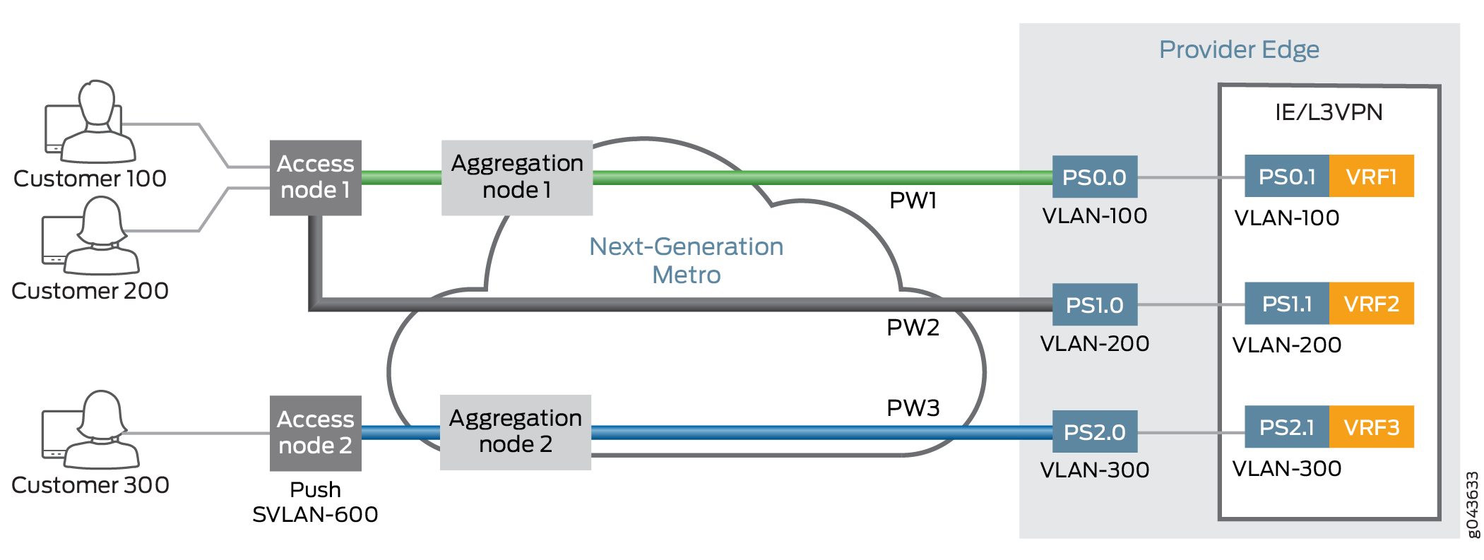
The following example shows the configuration of a pseudowire client logical interface configuration on a PE router from an access node:
interfaces {
    ps0 {
        anchor-point lt-3;
        unit 0 {
            encapsulation VLAN-ccc;
            VLAN ID 100;
        }
        unit 1 {
            VLAN ID 100;
            family inet;
        }
    }
}
Pseudowire Configuration from Aggregation Node
In this case, the aggregation node processes a stacked VLAN (also known as Q-in-Q). The pseudowire originates from aggregation node and terminates on a PE router. The aggregation node pushes the service VLAN (S-VLAN) tag, and the PE router is expected to operate on two VLAN tags—the outer VLAN tag corresponds to an S-VLAN and the inner VLAN tag corresponds to a C-VLAN. The VLAN ID configured on the transport PS interface at the PE router must match the VLAN tag of the S-VLAN. On the pseudowire client service logical interface, the outer VLAN tag must be configured to match the S-VLAN and the inner VLAN tag must be configured to match the C-VLAN.
Figure 5 provides the details of a transport PS interface from an aggregation node.
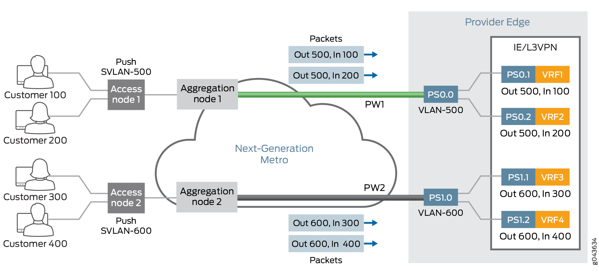
The following example shows the configuration of a pseudowire client logical interface configuration on a PE router from an aggregation node:
interfaces {
    ps0 {
        anchor-point lt-3;
        unit 0 {
            encapsulation VLAN-ccc;
            VLAN ID 500;
        }
        unit 1 {
            VLAN tags  {
                outer 500;
                inner 100;
            }
        }
        unit 2 {
            VLAN tags  {
                outer 500;
                inner 200;
            }
        }
    }
}
Transmitting Nonstandard BPDUs
CCC protocol (and Layer 2 Circuit and Layer 2 VPN) configurations can transmit nonstandard bridge protocol data units (BPDUs) generated by other vendors’ equipment. This is the default behavior on all supported PICs and requires no additional configuration.
The following PICs are supported on M320 and T Series routers:
1-port Gigabit Ethernet PIC
2-port Gigabit Ethernet PIC
4-port Gigabit Ethernet PIC
10-port Gigabit Ethernet PIC
TCC Overview
Translational cross-connect (TCC) is a switching concept that enables you to establish interconnections between a variety of Layer 2 protocols or circuits. It is similar to CCC. However, whereas CCC requires the same Layer 2 encapsulations on each side of a Juniper Networks router (such as PPP-to-PPP or Frame Relay-to-Frame Relay), TCC enables you to connect different types of Layer 2 protocols interchangeably. When you use TCC, combinations such as PPP-to-ATM (see Figure 6) and Ethernet-to-Frame Relay connections are possible.
The Layer 2 circuits and encapsulation types that can be interconnected by TCC are:
-
Ethernet
-
Extended VLANs
-
PPP
-
HDLC
-
ATM
-
Frame Relay
TCC works by removing the Layer 2 header when frames enter the router and adding a different Layer 2 header on the frames before they leave the router. In Figure 6, the PPP encapsulation is stripped from the frames arriving at Router B, and the ATM encapsulation is added before the frames are sent to Router C.
Note that all control traffic is terminated at the interconnecting router (Router B). Examples of traffic controllers include the Link Control Protocol (LCP) and the Network Control Protocol (NCP) for PPP, keepalives for HDLC, and Local Management Interface (LMI) for Frame Relay.
TCC functionality is different from standard Layer 2 switching. TCC only swaps Layer 2 headers. No other processing, such as header checksums, TTL decrementing, or protocol handling is performed. TCC is supported for IPv4 only.
Address Resolution Protocol (APR) packet policing on TCC Ethernet interfaces is effective for releases 10.4 and onwards.
You can configure TCC for interface switching and for Layer 2 VPNs. For more information about using TCC for virtual private networks (VPNs), see the Junos OS VPNs Library for Routing Devices.
Configuring Layer 2 Switching Cross-Connects Using CCC
Layer 2 switching cross-connects join logical interfaces to form what is essentially Layer 2 switching. The interfaces that you connect must be of the same type.
Figure 7 illustrates a Layer 2 switching cross-connect. In this topology, Router A and Router C have Frame Relay connections to Router B, which is a Juniper Networks router. Circuit cross-connect (CCC) allows you to configure Router B to act as a Frame Relay (Layer 2) switch.
To configure Router B to act as a Frame Relay switch, you configure a circuit from Router A to Router C that passes through Router B, effectively configuring Router B as a Frame Relay switch with respect to these routers. This configuration allows Router B to transparently switch packets (frames) between Router A and Router C without regard to the packets’ contents or the Layer 3 protocols. The only processing that Router B performs is to translate DLCI 600 to 750.
If the Router A–to–Router B and Router B–to–Router C circuits were PPP, for example, the Link Control Protocol and Network Control Protocol exchanges occur between Router A and Router C. These messages are handled transparently by Router B, allowing Router A and Router C to use various PPP options (such as header or address compression and authentication) that Router B might not support. Similarly, Router A and Router C exchange keepalives, providing circuit-to-circuit connectivity status.
You can configure Layer 2 switching cross-connects on PPP, Cisco HDLC, Frame Relay, Ethernet, and ATM circuits. In a single cross-connect, only like interfaces can be connected.
To configure Layer 2 switching cross-connects, you must configure the following on the router that is acting as the switch (Router B in Figure 7):
- Configuring the CCC Encapsulation for Layer 2 Switching Cross-Connects
- Configuring the CCC Connection for Layer 2 Switching Cross-Connects
- Configuring MPLS for Layer 2 Switching Cross-Connects
- Example: Configuring a Layer 2 Switching Cross-Connect
- Configuring Layer 2 Switching Cross-Connect on ACX5440
Configuring the CCC Encapsulation for Layer 2 Switching Cross-Connects
To configure Layer 2 switching cross-connects, configure the CCC encapsulation on the router that is acting as the switch (Router B in Figure 7).
You cannot configure families on CCC interfaces; that is, you
cannot include the family statement at the [edit interfaces interface-name unit logical-unit-number] hierarchy level.
For instructions for configuring the encapsulation for Layer 2 switching cross-connects, see the following sections:
- Configuring ATM Encapsulation for Layer 2 Switching Cross-Connects
- Configuring Ethernet Encapsulation for Layer 2 Switching Cross-Connects
- Configuring Ethernet VLAN Encapsulation for Layer 2 Switching Cross-Connects
- Configuring Aggregated Ethernet Encapsulation for Layer 2 Switching Cross-Connects
- Configuring Frame Relay Encapsulation for Layer 2 Switching Cross-Connects
- Configuring PPP and Cisco HDLC Encapsulation for Layer 2 Switching Cross-Connects
Configuring ATM Encapsulation for Layer 2 Switching Cross-Connects
For ATM circuits, specify the encapsulation when configuring the virtual circuit (VC). Configure each VC as a circuit or a regular logical interface by including the following statements:
at-fpc/pic/port {
    atm-options {
        vpi vpi-identifier maximum-vcs maximum-vcs;
    }
    unit logical-unit-number {
        encapsulation encapsulation-type;
        point-to-point; # Default interface type
        vci vpi-identifier.vci-identifier;
    }
}
You can include these statements at the following hierarchy levels:
[edit interfaces][edit logical-systems logical-system-name interfaces]
Configuring Ethernet Encapsulation for Layer 2 Switching Cross-Connects
For Ethernet circuits, specify ethernet-ccc in the encapsulation statement. This statement configures the entire
physical device. For these circuits to work, you must also configure
a logical interface (unit 0).
Ethernet interfaces with standard Tag Protocol Identifier (TPID)
tagging can use Ethernet CCC encapsulation. On M Series Multiservice
Edge Routers, except the M320, one-port Gigabit Ethernet, two-port
Gigabit Ethernet, four-port Gigabit Ethernet, and four-port Fast Ethernet
PICs can use Ethernet CCC encapsulation. On T Series Core Routers
and M320 routers, one-port Gigabit Ethernet and two-port Gigabit Ethernet
PICs installed in FPC2 can use Ethernet CCC encapsulation. When you
use this encapsulation type, you can configure the ccc family
only.
fe-fpc/pic/port {
    encapsulation ethernet-ccc;
    unit 0;
}
You can include these statements at the following hierarchy levels:
[edit interfaces][edit logical-systems logical-system-name interfaces]
Configuring Ethernet VLAN Encapsulation for Layer 2 Switching Cross-Connects
An Ethernet virtual LAN (VLAN) circuit can be configured using
either the vlan-ccc or extended-vlan-ccc encapsulation.
If you configure the extended-vlan-ccc encapsulation on
the physical interface, you cannot configure the inet family
on the logical interfaces. Only the ccc family is allowed.
If you configure the vlan-ccc encapsulation on the physical
interface, both the inet and ccc families are
supported on the logical interfaces. Ethernet interfaces in VLAN mode
can have multiple logical interfaces.
For encapsulation type vlan-ccc, VLAN IDs from 512
through 4094 are reserved for CCC VLANs. For the extended-vlan-ccc encapsulation type, all VLAN IDs 1 and higher are valid. VLAN ID
0 is reserved for tagging the priority of frames.
Some vendors use the proprietary TPIDs 0x9100 and 0x9901 to
encapsulate a VLAN-tagged packet into a VLAN-CCC tunnel to interconnect
a geographically separated metro Ethernet network. By configuring
the extended-vlan-ccc encapsulation type, a Juniper Networks
router can accept all three TPIDs (0x8100, 0x9100, and 0x9901).
Configure an Ethernet VLAN circuit with the vlan-ccc encapsulation as follows:
interfaces {
    type-fpc/pic/port {
        vlan-tagging;
        encapsulation vlan-ccc;
        unit logical-unit-number {
            encapsulation vlan-ccc;
            vlan-id vlan-id;
        }
    }
}
You can configure these statements at the following hierarchy levels:
[edit interfaces][edit logical-systems logical-system-name interfaces]
Configure an Ethernet VLAN circuit with the extended-vlan-ccc encapsulation statement as follows:
interfaces {
    type-fpc/pic/port {
        vlan-tagging;
        encapsulation extended-vlan-ccc;
        unit logical-unit-number {
            vlan-id vlan-id;
            family ccc;
        }
    }
}
You can configure these statements at the following hierarchy levels:
[edit interfaces][edit logical-systems logical-system-name interfaces]
Whether you configure the encapsulation as vlan-ccc or extended-vlan-ccc, you must enable VLAN tagging by
including the vlan-tagging statement.
Configuring Aggregated Ethernet Encapsulation for Layer 2 Switching Cross-Connects
You can configure aggregated Ethernet interfaces for CCC connections and for Layer 2 virtual private networks (VPNs).
Aggregated Ethernet interfaces configured with VLAN tagging
can be configured with multiple logical interfaces. The only encapsulation
available for aggregated Ethernet logical interfaces is vlan-ccc. When you configure the vlan-id statement, you are limited
to VLAN IDs 512 through 4094.
Aggregated Ethernet interfaces configured without VLAN tagging
can be configured only with the ethernet-ccc encapsulation.
All untagged Ethernet packets received are forwarded based on the
CCC parameters.
To configure aggregated Ethernet interfaces for CCC connections,
include the ae0 statement at the [edit interfaces] hierarchy level:
[edit interfaces]
ae0 {
    encapsulation (ethernet-ccc | extended-vlan-ccc | vlan-ccc);
    vlan-tagging;
    aggregated-ether-options {
        minimum-links links;
        link-speed speed;
    }
    unit logical-unit-number {
        encapsulation vlan-ccc;
        vlan-id identifier;
        family ccc;
    }
}
Be aware of the following limitations when configuring CCC connections over aggregated Ethernet interfaces:
If you configured load balancing between child links, be aware that a different hash key is used to distribute packets among the child links. Standard aggregated interfaces have family inet configured. An IP version 4 (IPv4) hash key (based on the Layer 3 information) is used to distribute packets among the child links. A CCC connection over an aggregated Ethernet interface has family ccc configured instead. Instead of an IPv4 hash key, an MPLS hash key (based on the destination media access control [MAC] address) is used to distributed packets among the child links.
The extended-vlan-ccc encapsulation is not supported on the 12-port Fast Ethernet PIC and the 48-port Fast Ethernet PIC.
The Junos OS does not support the Link Aggregation Control Protocol (LACP) when an aggregated interface is configured as a VLAN (with vlan-ccc encapsulation). LACP can be configured only when the aggregated interface is configured with the ethernet-ccc encapsulation.
For more information about how to configure aggregated Ethernet interfaces, see the Junos OS Network Interfaces Library for Routing Devices.
Configuring Frame Relay Encapsulation for Layer 2 Switching Cross-Connects
For Frame Relay circuits, specify the encapsulation when configuring the DLCI. Configure each DLCI as a circuit or a regular logical interface. The DLCI for regular interfaces must be from 1 through 511. For CCC interfaces, it must be from 512 through 4094.
interfaces {
    type-fpc/pic/port {
        unit logical-unit-number {
            dlci dlci-identifier;
            encapsulation encapsulation-type;
            point-to-point; # Default interface type
        }
    }
}
You can configure these statements at the following hierarchy levels:
[edit interfaces][edit logical-systems logical-system-name interfaces]
Configuring PPP and Cisco HDLC Encapsulation for Layer 2 Switching Cross-Connects
For PPP and Cisco HDLC circuits, specify the encapsulation in
the encapsulation statement. This statement configures
the entire physical device. For these circuits to work, you must configure
a logical interface (unit 0).
interfaces type-fpc/pic/port {
    encapsulation encapsulation-type;
    unit 0;
}
You can configure these statements at the following hierarchy levels:
[edit interfaces type-fpc/pic/port][edit logical-systems logical-system-name interfaces type-fpc/pic/port]
Configuring the CCC Connection for Layer 2 Switching Cross-Connects
To configure Layer 2 switching cross-connects, define the
connection between the two circuits by including the interface-switch statement. You configure this connection on the router that is acting
as the switch (Router B in Figure 7). The
connection joins the interface that comes from the circuit’s
source to the interface that leads to the circuit’s destination.
When you specify the interface names, include the logical portion
of the name, which corresponds to the logical unit number. The cross-connect
is bidirectional, so packets received on the first interface are transmitted
out the second interface, and those received on the second interface
are transmitted out the first.
interface-switch connection-name {
    interface interface-name.unit-number;
    interface interface-name.unit-number;
}
You can include this statement at the following hierarchy levels:
[edit protocols connections][edit logical-systems logical-system-name protocols connections]
Configuring MPLS for Layer 2 Switching Cross-Connects
For Layer 2 switching cross-connects to work, you must enable MPLS on the router by including at least the following statements. This minimum configuration enables MPLS on a logical interface for the switching cross-connect.
Include the family mpls statement:
family mpls;
You can configure this statement at the following hierarchy levels:
[edit interfaces interface-name unit logical-unit-number][edit logical-systems logical-system-name interfaces interface-name unit logical-unit-number]
You can then specify this logical interface in the MPLS protocol configuration:
mpls {
    interface interface-name; # Required to enable MPLS on the interface
}
You can configure these statements at the following hierarchy levels:
[edit protocols][edit logical-systems logical-system-name protocols]
Example: Configuring a Layer 2 Switching Cross-Connect
Configure a full-duplex Layer 2 switching cross-connect between Router A and Router C, using a Juniper Networks router, Router B, as the virtual switch. See the topology in Figure 8 and Figure 9.
[edit]
interfaces {
    so-1/0/0 {
        encapsulation frame-relay-ccc;
        unit 1 {
            point-to-point;
            encapsulation frame-relay-ccc;
            dlci 600;
        }
    }
    so-2/0/0 {
        encapsulation frame-relay-ccc;
        unit 2 {
            point-to-point;
            encapsulation frame-relay-ccc;
            dlci 750;
        }
    }
}
protocols {
    connections {
        interface-switch router-a-to-router-c {
            interface so-1/0/0.1;
            interface so-2/0/0.2;
        }
    }
    mpls {
        interface all;
    }
}
[edit]
interfaces {
    ge-2/1/0 {
        vlan-tagging;
        encapsulation vlan-ccc;
        unit 0 {
            encapsulation vlan-ccc;
            vlan-id 600;
        }
    }
    ge-2/2/0 {
        vlan-tagging;
        encapsulation vlan-ccc;
        unit 0 {
            encapsulation vlan-ccc;
            vlan-id 600;
        }
        unit 1 {
            family inet {
                vlan-id 1;
                address 10.9.200.1/24;
            }
        }
    }
}
protocols {
    mpls {
        interface all;
    }
    connections {
        interface-switch layer2-sw {
            interface ge-2/1/0.0;
            interface ge-2/2/0.0;
        }
    }
}
Configuring Layer 2 Switching Cross-Connect on ACX5440
Starting in Junos OS Release 19.3R1, you can leverage the hardware support available for cross-connects on the ACX5448 device with the Layer 2 local switching functionality using certain models. With this support, you can provide the EVP and Ethernet Virtual Private Line (EVPL) services..
Local-switching with the following forwarding models are supported:
VLAN-CCC (logical interface-level local-switching) without any map.
VLAN-CCC (logical interface-level local-switching) with the following vlan-maps:
Push 0x8100.pushVLAN (QinQ type)
Swap 0x8100.swapVLAN
Aggregated Ethernet (AE) static interfaces.
AE interfaces with LACP, load-balance all active mode.
Local-switching end-interface support for AE or LAG interface (one non-AE interface and other AE interface).
Local-switching both interface as AE or LAG interfaces.
To enable Layer 2 local switching on the ACX5448 device, you can use the existing configuration statements for Layer 2 circuits. For example,
[edit protocols l2circuit]
local-switching {
    interface interface1 {
        end-interface interface3;
        ignore-encapsulation-mismatch;
        ignore-mtu-mismatch;
    }
}
Configuring MPLS LSP Tunnel Cross-Connects Using CCC
MPLS tunnel cross-connects between interfaces and LSPs allow you to connect two distant interface circuits of the same type by creating MPLS tunnels that use LSPs as the conduit. The topology in Figure 10 illustrates an MPLS LSP tunnel cross-connect. In this topology, two separate networks, in this case ATM access networks, are connected through an IP backbone. CCC allows you to establish an LSP tunnel between the two domains. With LSP tunneling, you tunnel the ATM traffic from one network across a SONET backbone to the second network by using an MPLS LSP.
When traffic from Router A (VC 234) reaches Router B, it is encapsulated and placed into an LSP, which is sent through the backbone to Router C. At Router C, the label is removed, and the packets are placed onto the ATM permanent virtual circuit (PVC) (VC 591) and sent to Router D. Similarly, traffic from Router D (VC 591) is sent over an LSP to Router B, then placed on VC 234 to Router A.
You can configure LSP tunnel cross-connect on PPP, Cisco HDLC, Frame Relay, and ATM circuits. In a single cross-connect, only like interfaces can be connected.
When you use MPLS tunnel cross-connects to support IS-IS, you must ensure that the LSP’s maximum transmission unit (MTU) can, at a minimum, accommodate a 1492-octet IS-IS protocol data unit (PDU) in addition to the link-level overhead associated with the technology being connected.
For the tunnel cross-connects to work, the IS-IS frame size on the edge routers (Routers A and D in Figure 11) must be smaller than the LSP’s MTU.
Frame size values do not include the frame check sequence (FCS) or delimiting flags.
To determine the LSP MTU required to support IS-IS, use the following calculation:
IS-IS MTU (minimum 1492, default 1497) + frame overhead + 4 (MPLS shim header) = Minimum LSP MTU
The framing overhead varies based on the encapsulation being used. The following lists the IS-IS encapsulation overhead values for various encapsulations:
ATM
AAL5 multiplex—8 bytes (RFC 1483)
VC multiplex—0 bytes
Frame Relay
Multiprotocol—2 bytes (RFCs 1490 and 2427)
VC multiplex—0 bytes
HDLC—4 bytes
PPP—4 bytes
VLAN—21 bytes (802.3/LLC)
For IS-IS to work over VLAN-CCC, the LSP’s MTU must be at least 1513 bytes (or 1518 for 1497-byte PDUs). If you increase the size of a Fast Ethernet MTU above the default of 1500 bytes, you might need to explicitly configure jumbo frames on intervening equipment.
To modify the MTU, include the mtu statement when
configuring the logical interface family at the [edit interfaces interface-name unit logical-unit-number encapsulation family] hierarchy level.
For more information about setting the MTU, see the Junos OS Network Interfaces Library for Routing Devices.
To configure an LSP tunnel cross-connect, you must configure the following on the interdomain router (Router B in Figure 11):
- Configuring the CCC Encapsulation for LSP Tunnel Cross-Connects
- Configuring the CCC Connection for LSP Tunnel Cross-Connects
- Example: Configuring an LSP Tunnel Cross-Connect
Configuring the CCC Encapsulation for LSP Tunnel Cross-Connects
To configure LSP tunnel cross-connects, you must configure the CCC encapsulation on the ingress and egress routers (Router B and Router C, respectively, in Figure 11).
You cannot configure families on CCC interfaces; that is, you
cannot include the family statement at the [edit interfaces interface-name unit logical-unit-number] hierarchy level.
For PPP or Cisco HDLC circuits, include the encapsulation statement to configure the entire physical device. For these circuits
to work, you must configure logical unit 0 on the interface.
type-fpc/pic/port {
    encapsulation (ppp-ccc | cisco-hdlc-ccc);
    unit 0;
}
You can include these statements at the following hierarchy levels:
[edit interfaces][edit logical-systems logical-system-name interfaces]
For ATM circuits, specify the encapsulation when configuring the VC by including the following statements. For each VC, you configure whether it is a circuit or a regular logical interface.
at-fpc/pic/port {
    atm-options {
        vpi vpi-identifier maximum-vcs maximum-vcs;
    }
    unit logical-unit-number {
        point-to-point; # Default interface type
        encapsulation atm-ccc-vc-mux;
        vci vpi-identifier.vci-identifier;
    }
}
You can include these statements at the following hierarchy levels:
[edit interfaces][edit logical-systems logical-system-name interfaces]
For Frame Relay circuits, include the following statements to specify the encapsulation when configuring the DLCI. For each DLCI, you configure whether it is a circuit or a regular logical interface. The DLCI for regular interfaces must be in the range 1 through 511. For CCC interfaces, it must be in the range 512 through 1022.
type-fpc/pic/port {
    encapsulation frame-relay-ccc;
    unit logical-unit-number {
        point-to-point; # default interface type
        encapsulation frame-relay-ccc;
        dlci dlci-identifier;
    }
}
You can include these statements at the following hierarchy levels:
[edit interfaces][edit logical-systems logical-system-name interfaces]
For more information about the encapsulation statement,
see the Junos OS Network Interfaces Library for Routing Devices.
Configuring the CCC Connection for LSP Tunnel Cross-Connects
To configure LSP tunnel cross-connects, include the remote-interface-switch statement to define the connection between the two circuits on the
ingress and egress routers (Router B and Router C, respectively,
in Figure 11). The connection joins the interface
or LSP that comes from the circuit’s source to the interface
or LSP that leads to the circuit’s destination. When you specify
the interface name, include the logical portion of the name, which
corresponds to the logical unit number. For the cross-connect to be
bidirectional, you must configure cross-connects on two routers.
remote-interface-switch connection-name {
    interface interface-name.unit-number;
    transmit-lsp label-switched-path;
    receive-lsp label-switched-path;
}
You can include these statements at the following hierarchy levels:
[edit protocols connections][edit logical-systems logical-system-name protocols connections]
Example: Configuring an LSP Tunnel Cross-Connect
Configure a full-duplex MPLS LSP tunnel cross-connect from Router A to Router D, passing through Router B and Router C. See the topology in Figure 11.
On Router B:
[edit]
interfaces {
    at-7/1/1 {
        atm-options {
            vpi 1 maximum-vcs 600;
        }
        unit 1 {
            point-to-point; # default interface type
            encapsulation atm-ccc-vc-mux;
            vci 1.234;
        }
    }
}
protocols {
    connections {
        remote-interface-switch router-b-to-router-c {
            interface at-7/1/1.1;
            transmit-lsp lsp1;
            receive-lsp lsp2;
        }
    }
}
On Router C:
[edit]
interfaces {
    at-3/0/0 {
        atm-options {
            vpi 2 maximum-vcs 600;
        }
        unit 2 {
            point-to-point; # default interface type
            encapsulation atm-ccc-vc-mux;
            vci 2.591;
        }
    }
}
protocols {
    connections {
        remote-interface-switch router-b-to-router-c {
            interface at-3/0/0.2;
            transmit-lsp lsp2;
            receive-lsp lsp1;
        }
    }
}
Configuring TCC
This section describes how to configure translational cross-connect (TCC).
To configure TCC, you must perform the following tasks on the router that is acting as the switch:
- Configuring the Encapsulation for Layer 2 Switching TCCs
- Configuring the Connection for Layer 2 Switching TCCs
- Configuring MPLS for Layer 2 Switching TCCs
Configuring the Encapsulation for Layer 2 Switching TCCs
To configure a Layer 2 switching TCC, specify the TCC encapsulation on the desired interfaces of the router that is acting as the switch.
You cannot configure standard protocol families on TCC or CCC interfaces. Only the CCC family is allowed on CCC interfaces, and only the TCC family is allowed on TCC interfaces.
For Ethernet circuits and Ethernet extended VLAN circuits, you must also configure the Address Resolution Protocol (ARP). See Configuring ARP for Ethernet and Ethernet Extended VLAN Encapsulations.
- Configuring PPP and Cisco HDLC Encapsulation for Layer 2 Switching TCCs
- Configuring ATM Encapsulation for Layer 2 Switching TCCs
- Configuring Frame Relay Encapsulation for Layer 2 Switching TCCs
- Configuring Ethernet Encapsulation for Layer 2 Switching TCCs
- Configuring Ethernet Extended VLAN Encapsulation for Layer 2 Switching TCCs
- Configuring ARP for Ethernet and Ethernet Extended VLAN Encapsulations
Configuring PPP and Cisco HDLC Encapsulation for Layer 2 Switching TCCs
For PPP and Cisco HDLC circuits, configure the encapsulation
type for the entire physical device by specifying the appropriate
value for the encapsulation statement. For these circuits
to work, you must also configure the logical interface unit 0.
encapsulation (ppp-tcc | cisco-hdlc-tcc);
unit 0{...}
You can include these statements at the following hierarchy levels:
[edit interfaces interface-name][edit logical-systems logical-system-name interfaces interface-name]
Configuring ATM Encapsulation for Layer 2 Switching TCCs
For ATM circuits, configure the encapsulation type by specifying
the appropriate value for the encapsulation statement in
the virtual circuit (VC) configuration. Specify whether each VC is
a circuit or a regular logical interface.
atm-options {
    vpi vpi-identifier maximum-vcs maximum-vcs;
}
unit logical-unit-number {
    encapsulation (atm-tcc-vc-mux | atm-tcc-snap);
    point-to-point;
    vci vpi-identifier.vci-identifier;
}
You can include these statements at the following hierarchy levels:
[edit interfaces at-fpc/pic/port][edit logical-systems logical-system-name interfaces at-fpc/pic/port]
Configuring Frame Relay Encapsulation for Layer 2 Switching TCCs
For Frame Relay circuits, configure the encapsulation type by
specifying the value frame-relay-tcc for the encapsulation statement when configuring the data-link connection identifier (DLCI).
You configure each DLCI as a circuit or a regular logical interface.
The DLCI for regular interfaces must be in the range from 1 through
511, but for TCC and CCC interfaces it must be in the range from 512
through 1022.
encapsulation frame-relay-tcc;
unit logical-unit-number {
    dlci dlci-identifier;
    encapsulation frame-relay-tcc;
    point-to-point;
}
You can include these statements at the following hierarchy levels:
[edit interfaces interface-name][edit logical-systems logical-system-name interfaces interface-name]
Configuring Ethernet Encapsulation for Layer 2 Switching TCCs
For Ethernet TCC circuits, configuring the encapsulation type
for the entire physical device by specifying the value ethernet-tcc for the encapsulation statement.
You must also specify static values for a remote address and
a proxy address at the [edit interfaces interface-name unit unit-number family tcc] or [edit logical-systems logical-system-name interfaces interface-name unit unit-number family
tcc] hierarchy level.
The remote address is associated with the TCC switching router’s
Ethernet neighbor; in the remote statement you must specify
both the IP address and the media access control (MAC) address of
the Ethernet neighbor. The proxy address is associated with the TCC
router’s other neighbor connected by the unlike link; in the proxy statement you must specify the IP address of the non-Ethernet
neighbor.
You can configure Ethernet TCC encapsulation for the interfaces on 1-port Gigabit Ethernet, 2-port Gigabit Ethernet, 4-port Fast Ethernet, and 4-port Gigabit Ethernet PICs.
encapsulation ethernet-tcc;
unit logical-unit-number {
    family tcc {
        proxy {
            inet-address ip-address;
        }
        remote {
            inet-address ip-address;
            mac-address mac-address;
        }
    }
}
You can include these statements at the following hierarchy levels:
[edit interfaces (fe | ge)-fpc/pic/port][edit logical-systems logical-system-name interfaces (fe | ge)-fpc/pic/port]
For Ethernet circuits, you must also configure the Address Resolution Protocol (ARP). See Configuring ARP for Ethernet and Ethernet Extended VLAN Encapsulations.
Configuring Ethernet Extended VLAN Encapsulation for Layer 2 Switching TCCs
For Ethernet extended VLAN circuits, configure the encapsulation
type for the entire physical device by specifying the value extended-vlan-tcc for the encapsulation statement.
You must also enable VLAN tagging. Ethernet interfaces in VLAN
mode can have multiple logical interfaces. With encapsulation type extended-vlan-tcc, all VLAN IDs from 0 through 4094 are valid,
up to a maximum of 1024 VLANs. As with Ethernet circuits, you must
also specify a proxy address and a remote address at the [edit
interfaces interface-name unit logical-unit-number family tcc] or [edit logical-systems logical-system-name interfaces interface-name unit unit-number family tcc] hierarchy level (see Configuring Ethernet Encapsulation for Layer 2 Switching
TCCs).
encapsulation extended-vlan-tcc;
vlan-tagging;
unit logical-unit-number {
    vlan-id identifier;
    family tcc;
    proxy {
        inet-address ip-address;
    }
    remote {
        inet-address ip-address;
        mac-address mac-address;
    }
}
You can configure these statements at the following hierarchy levels:
[edit interfaces interface-name][edit logical-systems logical-system-name interfaces interface-name]
For Ethernet extended VLAN circuits, you must also configure the Address Resolution Protocol (ARP). See Configuring ARP for Ethernet and Ethernet Extended VLAN Encapsulations.
Configuring ARP for Ethernet and Ethernet Extended VLAN Encapsulations
For Ethernet and Ethernet extended VLAN circuits with TCC encapsulation, you must also configure ARP. Because TCC simply removes one Layer 2 header and adds another, the default form of dynamic ARP is not supported; you must configure static ARP.
Because remote and proxy addresses are specified on the router
performing TCC switching, you must apply the static ARP statement
to the Ethernet-type interfaces of the routers that connect to the
TCC-switched router. The arp statement must specify the
IP address and the MAC address of the remotely connected neighbor
by use of the unlike Layer 2 protocol on the far side of the
TCC switching router.
arp ip-address mac mac-address;
You can include this statement at the following hierarchy levels:
[edit interfaces interface-name unit logical-unit-number family inet address ip-address][edit logical-systems logical-system-name interfaces interface-name unit logical-unit-number family inet address ip-address]
Configuring the Connection for Layer 2 Switching TCCs
You must configure the connection between the two circuits of the Layer 2 switching TCC on the router acting as the switch. The connection joins the interface coming from the circuit’s source to the interface leading to the circuit’s destination. When you specify the interface names, include the logical portion of the name, which corresponds to the logical unit number. The cross-connect is bidirectional, so packets received on the first interface are transmitted from the second interface, and those received on the second interface are transmitted from the first.
To configure a connection for a local interface switch, include the following statements:
interface-switch connection-name {
    interface interface-name.unit-number;
}
lsp-switch connection-name {
    transmit-lsp lsp-number;
    receive-lsp lsp-number;
}
You can include these statements at the following hierarchy levels:
[edit protocols connections][edit logical-systems logical-system-name protocols connections]
To configure a connection for a remote interface switch, include the following statements:
remote-interface-switch connection-name {
    interface interface-name.unit-number;
    interface interface-name.unit-number;
    transmit-lsp lsp-number;
    receive-lsp lsp-number;
}
You can include these statements at the following hierarchy levels:
[edit protocols connections][edit logical-systems logical-system-name protocols connections]
Configuring MPLS for Layer 2 Switching TCCs
For a Layer 2 switching TCC to work, you must enable MPLS on the router by including at least the following statements. This minimum configuration enables MPLS on a logical interface for the switching cross-connect.
Include the family mpls statement:
family mpls;
You can configure this statement at the following hierarchy levels:
[edit interfaces interface-name unit logical-unit-number][edit logical-systems logical-system-name interfaces interface-name unit logical-unit-number]
You can then specify this logical interface in the MPLS protocol configuration:
mpls {
    interface interface-name; # Required to enable MPLS on the interface
}
You can configure these statements at the following hierarchy levels:
[edit protocols][edit logical-systems logical-system-name protocols]
MPLS LSP link protection does not support TCC.
CCC and TCC Graceful Restart
CCC and TCC graceful restart allows Layer 2 connections
between customer edge (CE) routers to restart gracefully. These Layer
2 connections are configured with the remote-interface-switch or lsp-switch statements. Because these CCC and TCC connections
have an implicit dependency on RSVP LSPs, graceful restart for CCC
and TCC uses the RSVP graceful restart capabilities.
RSVP graceful restart must be enabled on the PE routers and P routers to enable graceful restart for CCC and TCC. Also, because RSVP is used as the signaling protocol for signaling label information, the neighboring router must use helper mode to assist with the RSVP restart procedures.
Figure 12 illustrates how graceful restart might work on a CCC connection between two CE routers.
PE Router A is the ingress for the transmit LSP from PE Router A to PE Router B and the egress for the receive LSP from PE Router B to PE Router A. With RSVP graceful restart enabled on all the PE and P routers, the following occurs when PE router A restarts:
-
PE Router A preserves the forwarding state associated with the CCC routes (those from CCC to MPLS and from MPLS to CCC).
-
Traffic flows without disruption from CE router to CE router.
-
After the restart, PE Router A preserves the label for the LSP for which PE Router A is the egress (the receive LSP, for example). The transmit LSP from PE Router A to PE Router B can derive new label mappings, but should not cause any traffic disruption.
Configuring CCC and TCC Graceful Restart
To enable CCC and TCC graceful restart, include the graceful-restart statement:
graceful-restart;
You can include this statement at the following hierarchy levels:
[edit routing-options][edit logical-systems logical-system-name routing-options]
Configuring an MPLS-Based VLAN CCC Using the Connection Method (CLI Procedure)
You can configure an 802.1Q VLAN as an MPLS-based connection using EX8200 and EX4500 switches to interconnect multiple customer sites with Layer 2 technology.
This topic describes configuring provider edge (PE) switches in an MPLS network using a circuit cross-connect (CCC) on a tagged VLAN interface (802.1Q VLAN) rather than a simple interface.
You do not need to make any changes to existing provider switches in your MPLS network to support this type of configuration. For information on configuring provider switches, see Configuring MPLS on EX8200 and EX4500 Provider Switches.
You can send any kind of traffic over a CCC, including nonstandard bridge protocol data units (BPDUs) generated by other vendors’ equipment.
If you configure a physical interface as VLAN-tagged and with the vlan-ccc encapsulation, you cannot configure the associated logical interfaces with the inet family. Doing so could cause the logical interfaces to drop packets.
To configure a PE switch with a VLAN CCC and an MPLS-based connections:
Configuring CCC Switching for Point-to-Multipoint LSPs
You can configure circuit cross-connect (CCC) between two circuits to switch traffic from interfaces to point-to-multipoint LSPs. This feature is useful for handling multicast or broadcast traffic (for example, a digital video stream).
To configure CCC switching for point-to-multipoint LSPs, you do the following:
On the ingress provider edge (PE) router, you configure CCC to switch traffic from an incoming interface to a point-to-multipoint LSP.
On the egress PE, you configure CCC to switch traffic from an incoming point-to-multipoint LSP to an outgoing interface.
The CCC connection for point-to-multipoint LSPs is unidirectional.
For more information about point-to-multipoint LSPs, see Point-to-Multipoint LSPs Overview.
To configure a CCC connection for a point-to-multipoint LSP, complete the steps in the following sections:
- Configuring the Point-to-Multipoint LSP Switch on Ingress PE Routers
- Configuring Local Receivers on a Point-to-Multipoint CCC LSP Switch on Ingress PE Routers
- Configuring the Point-to-Multipoint LSP Switch on Egress PE Routers
Configuring the Point-to-Multipoint LSP Switch on Ingress PE Routers
To configure the ingress PE router with a CCC switch for a point-to-multipoint
LSP, include the p2mp-transmit-switch statement:
p2mp-transmit-switch switch-name {
    input-interface input-interface-name.unit-number;
    transmit-p2mp-lsp transmitting-lsp;
}
You can include the p2mp-transmit-switch statement
at the following hierarchy levels:
[edit protocols connections][edit logical-systems logical-system-name protocols connections]
switch-name specifies the name
of the ingress CCC switch.
input-interface input-interface-name.unit-number specifies the name of the
ingress interface.
transmit-p2mp-lsp transmitting-lsp specifies the name of the transmitting point-to-multipoint
LSP.
Configuring Local Receivers on a Point-to-Multipoint CCC LSP Switch on Ingress PE Routers
In addition to configuring an incoming CCC interface to a point-to-multipoint LSP on an ingress PE router, you can also configure CCC to switch traffic on an incoming CCC interface to one or more outgoing CCC interfaces by configuring output interfaces as local receivers.
To configure output interfaces, include the output-interface statement at the [edit protocols connections p2mp-transmit-switch p2mp-transmit-switch-name] hierarchy level.
[edit protocols connections]
p2mp-transmit-switch pc-ccc {
    input-interface fe-1/3/1.0;
    transmit-p2mp-lsp myp2mp;
    output-interface [fe-1/3/2.0 fe-1/3/3.0];
}
You can configure one or more output interfaces as local receivers on the ingress PE router using this statement.
Use the show connections p2mp-transmit-switch (extensive
| history | status), show route ccc <interface-name> (detail | extensive), and show route forwarding-table
ccc <interface-name> (detail | extensive) commands to view details of the local receiving interfaces on the
ingress PE router.
Configuring the Point-to-Multipoint LSP Switch on Egress PE Routers
To configure the CCC switch for a point-to-multipoint LSP on
the egress PE router, include the p2mp-receive-switch statement.
p2mp-receive-switch switch-name {
    output-interface [ output-interface-name.unit-number ];
    receive-p2mp-lsp receptive-lsp;
}
You can include this statement at the following hierarchy levels:
[edit protocols connections][edit logical-systems logical-system-name protocols connections]
switch-name specifies the name
of the egress CCC switch.
output-interface [ output-interface-name.unit-number ] specifies the name of one
or more egress interfaces.
receive-p2mp-lsp receptive-lsp specifies the name of the receptive point-to-multipoint LSP.
Configuring an MPLS-Based VLAN CCC Using a Layer 2 VPN (CLI Procedure)
You can configure an 802.1Q VLAN as an MPLS-based Layer 2 virtual private network (VPN) using EX8200 and EX4500 switches to interconnect multiple customer sites with Layer 2 technology.
This topic describes configuring provider edge (PE) switches in an MPLS network using a circuit cross-connect (CCC) on a tagged VLAN interface (802.1Q VLAN) rather than a simple interface.
You do not need to make any changes to existing provider switches in your MPLS network to support this type of configuration. For information on configuring provider switches, see Configuring MPLS on EX8200 and EX4500 Provider Switches.
You can send any kind of traffic over a CCC, including nonstandard bridge protocol data units (BPDUs) generated by other vendors’ equipment.
If you configure a physical interface as VLAN-tagged and with the vlan-ccc encapsulation, you cannot configure the associated logical interfaces with the inet family. Doing so could cause the logical interfaces to drop packets.
To configure a PE switch with a VLAN CCC and an MPLS-based Layer 2 VPN:
When you have completed configuring one PE switch, follow the same procedures to configure the other PE switch.
You must use the same type of switch for the other PE switch. You cannot use an EX8200 as one PE switch and use an EX3200 or EX4200 as the other PE switch.
Understanding Ethernet-over-MPLS (L2 Circuit)
Ethernet-over-MPLS allows sending Layer 2 (L2) Ethernet frames transparently over MPLS. Ethernet-over-MPLS uses a tunneling mechanism for Ethernet traffic through an MPLS-enabled Layer 3 core. It encapsulates Ethernet protocol data units (PDUs) inside MPLS packets and forwards the packets, using label stacking, across the MPLS network This technology has applications in service provider, enterprise and data center environments. For disaster recovery purposes, data centers are hosted in multiple sites that are geographically distant and interconnected using a WAN network.
A Layer 2 circuit is similar to a circuit cross-connect (CCC), except that multiple Layer 2 circuits can be transported over a single label-switched path (LSP) tunnel between two provider edge (PE) routers. In contrast, each CCC requires a dedicated LSP.
Ethernet-over-MPLS in Data Centers
For disaster recovery purposes, data centers are hosted in multiple sites that are geographically distant and interconnected using a WAN network. These data centers require L2 connectivity between them for the following reasons:
To replicate the storage over Fiber Channel IP (FCIP). FCIP works only on the same broadcast domain.
To run a dynamic routing protocol between the sites.
To support High Availability clusters that interconnect the nodes hosted in the various data centers.
See Also
Configuring Ethernet over MPLS (Layer 2 Circuit)
To implement Ethernet over MPLS, you must configure a Layer 2 circuit on the provider edge (PE) switches. No special configuration is required on the customer edge (CE) switches. The provider switches require MPLS and LDP to be configured on the interfaces that will be receiving and transmitting MPLS packets.
A Layer 2 circuit is similar to a circuit cross-connect (CCC), except that multiple Layer 2 circuits can be transported over a single label-switched path (LSP) tunnel between two PE switches. In contrast, each CCC requires a dedicated LSP.
This topic describes how to configure the PE switches to support Ethernet over MPLS. You must configure interfaces and protocols on both the local PE (PE1) and the remote PE (PE2) switches. The interface configuration varies depending upon whether the Layer 2 circuit is port-based or VLAN-based.
Starting in Junos OS Release 20.3R1, support for Layer 2 circuit to provide Layer 2 VPN and VPWS with LDP signaling.
Figure 13 shows an example of a Layer 2 circuit configuration.
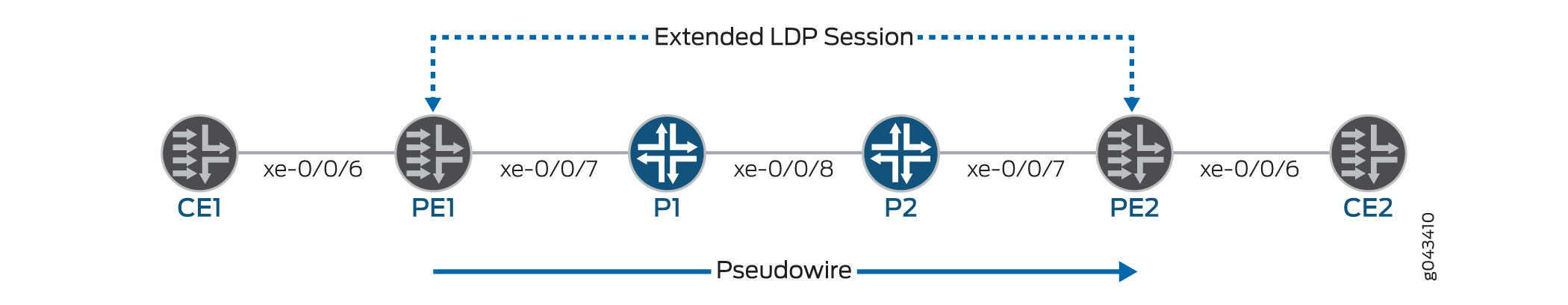
This topic refers to the local PE switch as PE1 and the remote PE switch as PE2. It also uses interface names rather than variables to help clarify the connections between the switches. The loopback addresses of the switches are configured as follows:
-
PE1: 10.127.1.1
-
PE2: 10.127.1.2
On QFX Series and EX4600 switches, the Layer 2 circuit CE facing interface does not support AE interfaces.
- Configuring the Local PE Switch for Port-Based Layer 2 Circuit (Pseudo-wire)
- Configuring the Remote PE Switch for Port-Based Layer 2 Circuit (Pseudo-wire)
- Configuring the Local PE Switch for VLAN-Based Layer 2 Circuit
- Configuring the Remote PE Switch for VLAN-Based Layer 2 Circuit
Configuring the Local PE Switch for Port-Based Layer 2 Circuit (Pseudo-wire)
Configure MPLS networks with an MTU (maximum transmission unit) that is at least 12 bytes larger than the largest frame size that will be transported by the LSPs. If the size of a encapsulated packet on the ingress LSR exceeds the LSP MTU, that packet is dropped. If an egress LSR receives a packet on a VC LSP with a length (after the label stack and sequencing control word have been popped) that exceeds the MTU of the destination layer 2 interface, that packet is also dropped.
To configure the local PE switch (PE1) for a port-based layer 2 circuit (pseudo-wire):
Configuring the Remote PE Switch for Port-Based Layer 2 Circuit (Pseudo-wire)
To configure the remote PE switch (PE2) for a port-based layer 2 circuit:
Configuring the Local PE Switch for VLAN-Based Layer 2 Circuit
To configure the local PE switch (PE1) for a VLAN-based layer 2 circuit:
Configuring the Remote PE Switch for VLAN-Based Layer 2 Circuit
To configure the remote PE switch (PE2) for a VLAN-based layer 2 circuit:
Change History Table
Feature support is determined by the platform and release you are using. Use Feature Explorer to determine if a feature is supported on your platform.