Basic LSP Configuration
Configuring LSP Metrics
The LSP metric is used to indicate the ease or difficulty of sending traffic over a particular LSP. Lower LSP metric values (lower cost) increase the likelihood of an LSP being used. Conversely, high LSP metric values (higher cost) decrease the likelihood of an LSP being used.
The LSP metric can be specified dynamically by the router or explicitly by the user as described in the following sections:
- Configuring Dynamic LSP Metrics
- Configuring Static LSP Metrics
- Configuring RSVP LSP Conditional Metrics
- Preserve the IGP Metric in RSVP LSP Routes
Configuring Dynamic LSP Metrics
If no specific metric is configured, an LSP attempts to track the IGP metric toward
the same destination (the to address of the LSP). IGP includes
OSPF, IS-IS, Routing Information Protocol (RIP), and static routes. BGP and other
RSVP or LDP routes are excluded.
For example, if the OSPF metric toward a router is 20, all LSPs toward that router automatically inherit metric 20. If the OSPF toward a router later changes to a different value, all LSP metrics change accordingly. If there are no IGP routes toward the router, the LSP raises its metric to 65,535.
Note that in this case, the LSP metric is completely determined by IGP; it bears no relationship to the actual path the LSP is currently traversing. If LSP reroutes (such as through reoptimization), its metric does not change, and thus it remains transparent to users. Dynamic metric is the default behavior; no configuration is required.
Configuring Static LSP Metrics
You can manually assign a fixed metric value to an LSP. Once configured with the
metric statement, the LSP metric is fixed and cannot
change:
metric number;
You can include this statement at the following hierarchy levels:
-
[edit protocols mpls label-switched-path lsp-name] -
[edit protocols mpls static-label-switched-path lsp-name] -
[edit logical-systems logical-system-name protocols mpls label-switched-path lsp-name] -
[edit logical-systems logical-system-name
                            protocols mpls static-label-switched-path
                            lsp-name]
The LSP metric has several uses:
-
When there are parallel LSPs with the same egress router, the metrics are compared to determine which LSP has the lowest metric value (the lowest cost) and therefore the preferred path to the destination. If the metrics are the same, the traffic is shared.
Adjusting the metric values can force traffic to prefer some LSPs over others, regardless of the underlying IGP metric.
-
When an IGP shortcut is enabled (see Using Labeled-Switched Paths to Augment SPF to Compute IGP Shortcuts), an IGP route might be installed in the routing table with an LSP as the next hop, if the LSP is on the shortest path to the destination. In this case, the LSP metric is added to the other IGP metrics to determine the total path metric. For example, if an LSP whose ingress router is X and egress router is Y is on the shortest path to destination Z, the LSP metric is added to the metric for the IGP route from Y to Z to determine the total cost of the path. If several LSPs are potential next hops, the total metrics of the paths are compared to determine which path is preferred (that is, has the lowest total metric). Or, IGP paths and LSPs leading to the same destination could be compared by means of the metric value to determine which path is preferred.
By adjusting the LSP metric, you can force traffic to prefer LSPs, prefer the IGP path, or share the load among them.
-
If router X and Y are BGP peers and if there is an LSP between them, the LSP metric represents the total cost to reach Y from X. If for any reason the LSP reroutes, the underlying path cost might change significantly, but X’s cost to reach Y remains the same (the LSP metric), which allows X to report through a BGP multiple exit discriminator (MED) a stable metric to downstream neighbors. As long as Y remains reachable through the LSP, no changes are visible to downstream BGP neighbors.
It is possible to configure IS-IS to ignore the configured LSP metric by including
the ignore-lsp-metrics statement at the [edit protocols
isis traffic-engineering shortcuts] hierarchy level. This statement
removes the mutual dependency between IS-IS and MPLS for path computation. For more
information, see the Junos OS Routing Protocols Library for Routing Devices.
Configuring RSVP LSP Conditional Metrics
Conditional metric provides the capability to use different metric values conditionally for local statically configured label-switched paths (LSPs). The conditional metrics are based on the dynamically changing IGP metric. Junos OS changes the LSP metric to the configured conditional metric that corresponds to the highest threshold reached by the IGP metric. If there are no matching conditions, the LSP uses the IGP metric of the route. You can configure up to four conditional metrics for an LSP and they will be in sorted order.
If you configure the track-igp-metric statement with the conditional
metric configuration, Junos OS uses the IGP metric of the installed routes to
evaluate the configured conditional metric. You cannot configure static metric along
with conditional metric.
Preserve the IGP Metric in RSVP LSP Routes
When you use the conditional-metric statement to configure RSVP
LSPs, the resulting metric might be different from the actual IGP metric for the
LSP destination. RSVP programs the LSP ingress route with this conditional metric as
the route’s metric. But in certain situations, there may be a need to preserve the
actual IGP metric used by conditional metric for later use, such as calculating the
BGP MED value.
Use the include-igp-metric statement in conjunction with the
conditional-metric statement to include the IGP metric
information in the RSVP route.
Run the show route protocol rsvp extensive command to view the
updated actual IGP cost.
This is only applicable to RSVP routes using the conditional metric. RSVP routes that use dynamic IGP include the IGP metric by default.
For more information, see the include-igp-metric configuration statement.
Configuring a Text Description for LSPs
You can provide a textual description for an LSP by enclosing any descriptive text that
includes spaces within quotation marks (" "). The descriptive text you include is displayed in
the detail output of the show mpls lsp or the show mpls
container-lsp command.
Adding a text description for an LSP has no effect on the operation of the LSP. The LSP text description can be no more than 80 characters in length.
To provide a textual description for an LSP, include the description
statement at any of the following hierarchy levels:
-
[edit protocols mpls label-switched-path lsp-name] -
[edit protocols mpls container-label-switched-path lsp-name] -
[edit protocols mpls static-label-switched-path lsp-name] -
[edit logical-systems logical-system-name protocols mpls label-switched-path lsp-name] -
[edit logical-systems logical-system-name protocols mpls static-label-switched-path
            lsp-name]
Before you begin:
-
Configure the device interfaces.
-
Configure the device for network communication.
-
Enable MPLS on the device interfaces.
-
Configure an LSP in the MPLS domain.
To add a text description for an LSP:
-
Enter any text describing the LSP.
[edit protocols mpls lsp lsp-name]
user@host# set description text
For example:
[edit protocols mpls lsp LSP1]
user@host# set description “Connecting remote device”
-
Verify and commit the configuration.
For example:
[edit protocols mpls lsp]
user@host# set protocols mpls label-switched-path LSP1 to 10.1.1.1
user@host# set protocols mpls label-switched-path LSP1 description "Connecting remote device"
user@host# set protocols mpls interface ge-1/0/8.0
[edit]
user@host# commit
commit complete
-
View the description of an LSP using the
show mpls lsp detailorshow mpls container-lsp detailcommand, depending on the type of LSP configured.user@host> show mpls lsp detail Ingress LSP: 1 sessions 10.1.1.1 From: 0.0.0.0, State: Up, ActiveRoute: 1, LSPname: LSP1 Description: Connecting remote device ActivePath: (none) LSPtype: Static Configured, Penultimate hop popping LoadBalance: Random Encoding type: Packet, Switching type: Packet, GPID: IPv4 Primary State: Up Priorities: 7 0 SmartOptimizeTimer: 180 No computed ERO. Total 1 displayed, Up 1, Down 0 Egress LSP: 0 sessions Total 0 displayed, Up 0, Down 0 Transit LSP: 0 sessions Total 0 displayed, Up 0, Down 0
Configuring MPLS Soft Preemption
Soft preemption attempts to establish a new path for a preempted LSP before tearing down the original LSP. The default behavior is to tear down a preempted LSP first, signal a new path, and then reestablish the LSP over the new path. In the interval between when the path is taken down and the new LSP is established, any traffic attempting to use the LSP is lost. Soft preemption prevents this type of traffic loss. The trade-off is that during the time when an LSP is being soft preempted, two LSPs with their corresponding bandwidth requirements are used until the original path is torn down.
MPLS soft preemption is useful for network maintenance. For example, you can move all LSPs away from a particular interface, then take the interface down for maintenance without interrupting traffic. MPLS soft preemption is described in detail in RFC 5712, MPLS Traffic Engineering Soft Preemption.
Soft preemption is a property of the LSP and is disabled by
default. You configure it at the ingress of an LSP by including the soft-preemption statement:
soft-preemption;
You can include this statement at the following hierarchy levels:
[edit protocols mpls label-switched-path lsp-name][edit logical-systems logical-system-name protocols mpls label-switched-path lsp-name]
You can also configure a timer for soft preemption. The timer designates the length of time the router should wait before initiating a hard preemption of the LSP. At the end of the time specified, the LSP is torn down and resignaled. The soft-preemption cleanup timer has a default value of 30 seconds; the range of permissible values is 0 through 180 seconds. A value of 0 means that soft preemption is disabled. The soft-preemption cleanup timer is global for all LSPs.
Configure the timer by including the cleanup-timer statement:
cleanup-timer seconds;
You can include this statement at the following hierarchy levels:
[edit protocols rsvp preemption soft-preemption][edit logical-systems logical-system-name protocols rsvp preemption soft-preemption]
Soft preemption cannot be configured on LSPs for which fast reroute has been configured. The configuration fails to commit. However, you can enable soft preemption in conjunction with node and link protection.
The counter value for SoftPreemptionCnt initializes with a value of 0 (zero), visible in the command show rsvp interface detail output.
Configuring Priority and Preemption for LSPs
When there is insufficient bandwidth to establish a more important LSP, you might want to tear down a less important existing LSP to free the bandwidth. You do this by preempting the existing LSP.
Whether an LSP can be preempted is determined by two properties associated with the LSP:
Setup priority—Determines whether a new LSP that preempts an existing LSP can be established. For preemption to occur, the setup priority of the new LSP must be higher than that of the existing LSP. Also, the act of preempting the existing LSP must produce sufficient bandwidth to support the new LSP. That is, preemption occurs only if the new LSP can be set up successfully.
Reservation priority—Determines the degree to which an LSP holds on to its session reservation after the LSP has been set up successfully. When the reservation priority is high, the existing LSP is less likely to give up its reservation, and hence it is unlikely that the LSP can be preempted.
You cannot configure an LSP with a high setup priority and a low reservation priority, because permanent preemption loops might result if two LSPs are allowed to preempt each other. You must configure the reservation priority to be higher than or equal to the setup priority.
The setup priority also defines the relative importance of LSPs on the same ingress router. When the software starts, when a new LSP is established, or during fault recovery, the setup priority determines the order in which LSPs are serviced. Higher-priority LSPs tend to be established first and hence enjoy more optimal path selection.
To configure the LSP’s preemption properties, include
the priority statement:
priority setup-priority reservation-priority;
For a list of hierarchy levels at which you can include this statement, see the statement summary section for this statement.
Both setup-priority and reservation-priority can be a value from
0 through 7. The value 0 corresponds to the highest priority, and
the value 7 to the lowest. By default, an LSP has a setup priority
of 7 (that is, it cannot preempt any other LSPs) and a reservation
priority of 0 (that is, other LSPs cannot preempt it). These defaults
are such that preemption does not happen. When you are configuring
these values, the setup priority should always be less than or equal
to the hold priority.
Configuring Administrative Groups for LSPs
Administrative groups, also known as link coloring or resource class, are manually assigned attributes that describe the “color” of links, such that links with the same color conceptually belong to the same class. You can use administrative groups to implement a variety of policy-based LSP setups.
Administrative groups are meaningful only when constrained-path LSP computation is enabled.
You can assign up to 32 names and values (in the range 0 through 31), which define a series of names and their corresponding values. The administrative names and values must be identical across all routers within a single domain.
The administrative value is distinct from the priority.
You configure the priority for an LSP using the priority statement. See Configuring Priority
and Preemption for LSPs.
To configure administrative groups, follow these steps:
Define multiple levels of service quality by including the
admin-groupsstatement:admin-groups { group-name group-value; }
You can include this statement at the following hierarchy levels:
[edit protocols mpls][edit logical-systems logical-system-name protocols mpls]
The following configuration example illustrates how you might configure a set of administrative names and values for a domain:
[edit protocols mpls]
admin-groups {
    gold 1;
    silver 2;
    copper 3;
    best-effort 4;
}
Define the administrative groups to which an interface belongs. You can assign multiple groups to an interface. Include the
interfacestatement:interface interface-name { admin-group [ group-names ]; }
You can include this statement at the following hierarchy levels:
[edit protocols mpls][edit logical-systems logical-system-name protocols mpls]
If you do not include the
admin-groupstatement, an interface does not belong to any group.IGPs use the group information to build link-state packets, which are then flooded throughout the network, providing information to all nodes in the network. At any router, the IGP topology, as well as administrative groups of all the links, is available.
Changing the interface’s administrative group affects only new LSPs. Existing LSPs on the interface are not preempted or recomputed to keep the network stable. If LSPs need to be removed because of a group change, issue the
clear rsvp sessioncommand.Note:When configuring administrative groups and extended administrative groups together for a link, both the types of administrative groups must be configured on the interface.
Configure an administrative group constraint for each LSP or for each primary or secondary LSP path. Include the
label-switched-pathstatement:label-switched-path lsp-name { to address; ... admin-group { exclude [ group-names ]; include-all [ group-names ]; include-any [ group-names ]; } primary path-name { admin-group { exclude [ group-names ]; include-all [ group-names ]; include-any [ group-names ]; } } secondary path-name { admin-group { exclude [ group-names ]; include-all [ group-names ]; include-any [ group-names ]; } } }
You can include the
label-switched-pathstatement at the following hierarchy levels:[edit protocols mpls][edit logical-systems logical-system-name protocols mpls]
If you omit the
include-all,include-any, orexcludestatements, the path computation proceeds unchanged. The path computation is based on the constrained-path LSP computation. For information about how the constrained-path LSP computation is calculated, see How CSPF Selects a Path.Note:Changing the LSP’s administrative group causes an immediate recomputation of the route; therefore, the LSP might be rerouted.
Configuring Extended Administrative Groups for LSPs
In MPLS traffic engineering, a link can be configured with a set of administrative groups (also known as colors or resource classes). Administrative groups are carried in the interior gateway protocol (IGP) (OSPFv2 and IS-IS) as a 32-bit value assigned to each link. Juniper Networks routers normally interpret this 32-bit value as a bit mask with each bit representing a group, limiting each network to a total of 32 distinct administrative groups (value range 0 through 31).
You configure extended administrative groups, represented by a 32-bit value, expanding the number of administrative groups supported in the network beyond just 32. The original range of values available for administrative groups is still supported for backwards compatibility.
The extended administrative groups configuration accepts a set of interfaces with a corresponding set of extended administrative group names. It converts the names into a set of 32-bit values and propagates this information into the IGP. The extended administrative group values are global and must be identically configured on all the supported routers participating in the network. The domain-wide extended administrative groups database, learned from other routers through IGP flooding, is used by Constrained Shortest Path First (CSPF) for path computation.
The following procedure describes how to configure extended administrative groups:
When configuring administrative groups and extended administrative groups together for a link, both the types of administrative groups must be configured on the interface.
Configuring Preference Values for LSPs
As an option, you can configure multiple LSPs between the same pair of ingress and egress routers. This is useful for balancing the load among the LSPs because all LSPs, by default, have the same preference level. To prefer one LSP over another, set different preference levels for individual LSPs. The LSP with the lowest preference value is used. The default preference for RSVP LSPs is 7 and for LDP LSPs is 9. These preference values are lower (more preferred) than all learned routes except direct interface routes.
To change the default preference value, include the preference statement:
preference preference;
For a list of hierarchy levels at which you can include this statement, see the statement summary section for this statement.
Disabling Path Route Recording by LSPs
The Junos implementation of RSVP supports the Record Route object,
which allows an LSP to actively record the routers through which it
transits. You can use this information for troubleshooting and to
prevent routing loops. By default, path route information is recorded.
To disable recording, include the no-record statement:
no-record;
For a list of hierarchy levels at which you can include the record and no-record statements, see the statement
summary section for the statement.
Achieving a Make-Before-Break, Hitless Switchover for LSPs
Adaptive label-switched paths (LSPs) might need to establish a new LSP instance and transfer traffic from an old LSP instance onto the new LSP instance before tearing down the old one. This type of configuration is referred to as a make before break (MBB).
RSVP-TE is a protocol used to establish LSPs in MPLS networks. The Junos OS implementation of RSVP-TE to achieve a hitless (no traffic loss) MBB switchover has relied on configuring the timer values in the following configuration statements:
optimize-switchover-delay—Amount of time to wait before switching to the new LSP instance.optimize-hold-dead-delay—Amount of time to wait after switchover and before deletion of the old LSP instance.
Both the optimize-switchover-delay and optimize-hold-dead-delay statements apply to all LSPs that
use the make-before-break behavior for LSP setup and teardown, not
just for LSPs for which the optimize-timer statement has
also been configured. The following MPLS features cause LSPs to be
set up and torn down using make-before-break behavior:
Adaptive LSPs
Automatic bandwidth allocation
BFD for LSPs
Graceful Routing Engine switchover
Link and node protection
Nonstop active routing
Optimized LSPs
Point-to-multipoint (P2MP) LSPs
Soft preemption
Standby secondary paths
Both the optimize-switchover-delay and optimize-hold-dead-delay statements when configured add an artificial delay to the MBB process.
The value of the optimize-switchover-delay statement varies
with the size of the Explicit Route Objects (EROs). An ERO is an extension
to RSVP that allows an RSVP PATH message to traverse an explicit sequence
of routers that is independent of conventional shortest-path IP routing.
The value of the optimize-switchover-delay statement also
depends on the CPU load on each of the routers on the path. Customers
set the optimize-switchover-delay statement by trial and
error.
The value of the optimize-hold-dead-delay statement
depends on how fast the ingress router moves all application prefixes
to point to the new LSP. This is determined by the Packet Forwarding
Engine load, which can vary from platform to platform. Customers have
to set the optimize-hold-dead-delay statement by trial
and error.
However, as of Release 15.1, Junos OS is able to achieve a hitless MBB switchover without configuring the artificial delays that such timer values introduce.
This topic summarizes the three methods of achieving a MBB switchover from an old LSP to a new LSP using Junos OS:
- Specifying the Amount of Time the Router Waits to Switch Over to New Paths
- Specifying the Amount of Time to Delay the Tear Down of Old Paths
- Achieving a Hitless, MBB Switchover Without Artificial Delays
Specifying the Amount of Time the Router Waits to Switch Over to New Paths
To specify the amount of time the router waits to switch over
LSP instances to newly optimized paths, use the optimize-switchover-delay statement. You only need to configure this statement on routers
acting as the ingress for the affected LSPs (you do not need to configure
this statement on transit or egress routers). The timer in this statement
helps to ensure that the new optimized paths have been established
before traffic is switched over from the old paths. This timer can
only by enabled or disabled for all of the LSPs configured on the
router.
To configure the amount of time the router waits to switch over
LSP instances to newly optimized paths, specify the time in seconds
by using the optimize-switchover-delay statement:
optimize-switchover-delay seconds;
You can include this statement at the following hierarchy levels:
[edit protocols mpls][edit logical-systems logical-system-name protocols mpls]
Specifying the Amount of Time to Delay the Tear Down of Old Paths
To specify the amount of time to delay the tear down of old
paths after the router has switched traffic to new optimized paths,
use the optimize-hold-dead-delay statement. You only need
to configure this statement on routers acting as the ingress for the
affected LSPs (you do not need to configure this statement on transit
or egress routers). The timer in this statement helps to ensure that
old paths are not torn down before all routes have been switched over
to the new optimized paths. This timer can be enabled for specific
LSPs or for all of the LSPs configured on the router.
To configure the amount of time in seconds to delay the tear
down of old paths after the router has switched traffic to new optimized
paths, use the optimize-hold-dead-delay statement:
optimize-hold-dead-delay seconds;
For a list of hierarchy levels at which you can include this statement, see the statement summary section for this statement.
Achieving a Hitless, MBB Switchover Without Artificial Delays
As of Junos OS Release 15.1, there is another way to relinquish
the old LSP instances after MBB switchover without relying on the
arbitrary time intervals set up by the optimize-switchover-delay or optimize-hold-dead-delay statement. For example,
if you use the optimize-hold-dead-delay statement, you
configure a time you think it is safe to wait before tearing down
the old LSP instance after MBB. However, some routes might still be
in the process of shifting to the new instance. Tearing down the old
LSP instance prematurely results in one of the transit nodes dropping
the traffic for those routes that have not shifted to the new LSP
instance.
To avoid traffic loss, instead of using the optimize-switchover-delay statement, you can use MPLS-OAM (lsp ping), which confirms that
the LSP data plane is established end-to-end. Instead of using the optimize-hold-dead-delay statement, you can use a feedback
mechanism from the rpd infrastructure that confirms that all prefixes
referring to the old LSP have been switched over. The feedback mechanism
is sourced from the Tag library and relies on the routing protocol
process (rpd) infrastructure to determine when all the routes using
the old LSP instance have fully shifted to the new LSP instance after
MBB switchover.
The feedback mechanism is always in place, and it is optional.
Configure the optimize-adaptive-teardown statement to have
the feedback mechanism used during MBB switchover. This feature is
not supported for RSVP point-to-multipoint (P2MP) LSP instances. Global
configuration of the optimize-adaptive-teardown statement
only affects the point-to-point LSPs that are configured in the system.
You only need to configure the optimize-adaptive-teardown statement on routers acting as the ingress for the affected LSPs
(you do not need to configure this statement on transit or egress
routers). This feedback mechanism ensures that old paths are not torn
down before all routes have been switched over to the new optimized
paths. The global configuration of this configuration statement affects
only the point-to-point LSPs that are configured in the system.
optimize-adaptive-teardown {
    p2p:
}
You can include this statement at the [edit protocols mpls] hierarchy level.
Optimizing Signaled LSPs
Once an LSP has been established, topology or resources changes might, over time, make the path suboptimal. A new path might have become available that is less congested, has a lower metric, and traverses fewer hops. You can configure the router to recompute paths periodically to determine whether a more optimal path has become available.
If reoptimization is enabled, an LSP can be rerouted through different paths by constrained-path recomputations. However, if reoptimization is disabled, the LSP has a fixed path and cannot take advantage of newly available network resources. The LSP is fixed until the next topology change breaks the LSP and forces a recomputation.
Reoptimization is not related to failover. A new path is always computed when topology failures occur that disrupt an established path.
Because of the potential system overhead involved, you need
to carefully control the frequency of reoptimization. Network stability
might suffer when reoptimization is enabled. By default, the optimize-timer statement is set to 0 (that is, it is disabled).
LSP optimization is meaningful only when constrained-path LSP
computation is enabled, which is the default behavior. For more information
about constrained-path LSP computation, see Disabling Constrained-Path LSP Computation. Also, LSP
optimization is only applicable to ingress LSPs, so it is only necessary
to configure the optimize-timer statement on the ingress
router. The transit and egress routers require no specific configuration
to support LSP optimization (other than to have MPLS enabled).
To enable path reoptimization, include the optimize-timer statement:
optimize-timer seconds;
For a list of hierarchy levels at which you can include this statement, see the statement summary section for this statement.
Once you have configured the optimize-timer statement,
the reoptimization timer continues its countdown to the configured
value even if you delete the optimize-timer statement from
the configuration. The next optimization uses the new value. You can
force the Junos OS to use a new value immediately by deleting the
old value, committing the configuration, configuring the new value
for the optimize-timer statement, and then committing the
configuration again.
After reoptimization is run, the result is accepted only if it meets the following criteria:
The new path is not higher in IGP metric. (The metric for the old path is updated during computation, so if a recent link metric changed somewhere along the old path, it is accounted for.)
If the new path has the same IGP metric, it is not more hops away.
The new path does not cause preemption. (This is to reduce the ripple effect of preemption causing more preemption.)
The new path does not worsen congestion overall.
The relative congestion of the new path is determined as follows:
The percentage of available bandwidth on each link traversed by the new path is compared to that for the old path, starting from the most congested links.
For each current (old) path, the software stores the four smallest values for bandwidth availability for the links traversed in ascending order.
The software also stores the four smallest bandwidth availability values for the new path, corresponding to the links traversed in ascending order.
If any of the four new available bandwidth values are smaller than any of the corresponding old bandwidth availability values, the new path has at least one link that is more congested than the link used by the old path. Because using the link would cause more congestion, traffic is not switched to this new path.
If none of the four new available bandwidth values is smaller than the corresponding old bandwidth availability values, the new path is less congested than the old path.
When all the above conditions are met, then:
If the new path has a lower IGP metric, it is accepted.
If the new path has an equal IGP metric and lower hop count, it is accepted.
If you choose
least-fillas a load balancing algorithm, LSPs are load balanced as follows:The LSP is moved to a new path that is utilized at least 10% less than the current path. This might reduce congestion on the current path by only a small amount. For example, if an LSP with 1 MB of bandwidth is moved off a path carrying a minimum of 200 MB, congestion on the original path is reduced by less than 1%.
For
randomormost-fillalgorithms, this rule does not apply.
The following example illustrates how the
least-fillload balancing algorithm works.Figure 1: least-fill Load Balancing Algorithm Example
As shown in Figure 1, there are two potential paths for an LSP to traverse from router A to router H, the odd links from L1 through L13 and the even links from L2 through L14. Currently, the router is using the even links as the active path for the LSP. Each link between the same two routers (for example, router A and router B) has the same bandwidth:
L1, L2 = 10GE
L3, L4 = 1GE
L5, L6 = 1GE
L7, L8 = 1GE
L9, L10 = 1GE
L11, L12 = 10GE
L13, L14 = 10GE
The 1GE links are more likely to be congested. In this example, the odd 1GE links have the following available bandwidth:
L3 = 41%
L5 = 56%
L7 = 66%
L9 = 71%
The even 1GE links have the following available bandwidth:
L4 = 37%
L6 = 52%
L8 = 61%
L10 = 70%
Based on this information, the router would calculate the difference in available bandwidth between the odd links and the even links as follows:
L4 - L3 = 41% - 37% = 4%
L6 - L5 = 56% - 52% = 4%
L8 - L7 = 66% - 61% = 5%
L10 - L9 = 71% - 70% = 1%
The total additional bandwidth available over the odd links is 14% (4% + 4% + 5% + 1%). Since 14% is greater than 10% (the least-fill algorithm minimum threshold), the LSP is moved to the new path over the odd links from the original path using the even links.
Otherwise, the new path is rejected.
You can disable the following reoptimization criteria (a subset of the criteria listed previously):
If the new path has the same IGP metric, it is not more hops away.
The new path does not cause preemption. (This is to reduce the ripple effect of preemption causing more preemption.)
The new path does not worsen congestion overall.
If the new path has an equal IGP metric and lower hop count, it is accepted.
To disable them, either issue the clear mpls lsp optimize-aggressive command or include the optimize-aggressive statement:
optimize-aggressive;
You can include this statement at the following hierarchy levels:
[edit protocols mpls][edit logical-systems logical-system-name protocols mpls]
Including the optimize-aggressive statement in the
configuration causes the reoptimization procedure to be triggered
more often. Paths are rerouted more frequently. It also limits the
reoptimization algorithm to the IGP metric only.
Configuring the Smart Optimize Timer for LSPs
Because of network and router resource constraints, it is typically inadvisable to configure a short interval for the optimize timer. However, under certain circumstances, it might be desirable to reoptimize a path sooner than would normally be provided by the optimize timer.
For example, an LSP is traversing a preferred path that subsequently fails. The LSP is then switched to a less desirable path to reach the same destination. Even if the original path is quickly restored, it could take an excessively long time for the LSP to use it again, because it has to wait for the optimize timer to reoptimize the network paths. For such situations, you might want to configure the smart optimize timer.
When you enable the smart optimize timer, an LSP is switched back to its original path so long as the original path has been restored within 3 minutes of going down. Also, if the original path goes down again within 60 minutes, the smart optimize timer is disabled, and path optimization behaves as it normally does when the optimize timer alone is enabled. This prevents the router from using a flapping link.
The smart optimize timer is dependant on other MPLS features to function properly. For the scenario described here in which an LSP is switched to an alternate path in the event of a failure on the original path, it is assumed that you have configured one or more of the MPLS traffic protection features, including fast reroute, link protection, and standby secondary paths. These features help to ensure that traffic can reach its destination in the event of a failure.
At the least, you must configure a standby secondary path for the smart optimize timer feature to work properly. Fast reroute and link protection are more temporary solutions to a network outage. A secondary path ensures that there is a stable alternate path in the event the primary path fails. If you have not configured any sort of traffic protection for an LSP, the smart optimize timer by itself does not ensure that traffic can reach its destination. For more information about MPLS traffic protection, see MPLS and Traffic Protection.
When a primary path fails and the smart optimize timer switches traffic to the secondary path, the router might continue to use the secondary path even after the primary path has been restored. If the ingress router completes a CSPF calculation, it might determine that the secondary path is the better path.
This might be undesirable if the primary path should be the active path and the secondary path should be used as a backup only. Also, if the secondary path is being used as the active path (even though the primary path has been reestablished) and the secondary path fails, the smart optimize timer feature will not automatically switch traffic back to the primary path. However, you can enable protection for the secondary path by configuring node and link protection or an additional standby secondary path, in which case, the smart optimize timer can be effective.
Specify the time in seconds for the smart optimize timer
using the smart-optimize-timer statement:
You can apply the smart-optimize-timer configuration statement only
if you enable periodic LSP re-optimziation by using the
optimize-timer statement.
smart-optimize-timer seconds;
You can include this statement at the following hierarchy levels:
[edit protocols mpls][edit logical-systems logical-system-name protocols mpls]
Limiting the Number of Hops in LSPs
By default, each LSP can traverse a maximum of 255 hops, including
the ingress and egress routers. To modify this value, include the hop-limit statement:
hop-limit number;
For a list of hierarchy levels at which you can include this statement, see the statement summary section for this statement.
The number of hops can be from 2 through 255. (A path with two hops consists of the ingress and egress routers only.)
Configuring the Bandwidth Value for LSPs
Each LSP has a bandwidth value. This value is included in the sender’s Tspec field in RSVP path setup messages. You can specify a bandwidth value in bits per second. If you configure more bandwidth for an LSP, it should be able to carry a greater volume of traffic. The default bandwidth is 0 bits per second.
A nonzero bandwidth requires that transit and egress routers reserve capacity along the outbound links for the path. The RSVP reservation scheme is used to reserve this capacity. Any failure in bandwidth reservation (such as failures at RSVP policy control or admission control) might cause the LSP setup to fail. If there is insufficient bandwidth on the interfaces for the transit or egress routers, the LSP is not established.
To specify a bandwidth value for a signaled LSP, include
the bandwidth statement:
bandwidth bps;
For a list of hierarchy levels at which you can include this statement, see the statement summary section for this statement.
Automatic Bandwidth Allocation for LSPs
Automatic bandwidth allocation allows an MPLS tunnel to automatically adjust its bandwidth allocation based on the volume of traffic flowing through the tunnel. You can configure an LSP with minimal bandwidth; this feature can dynamically adjust the LSP’s bandwidth allocation based on current traffic patterns. The bandwidth adjustments do not interrupt traffic flow through the tunnel.
You set a sampling interval on an LSP configured with automatic bandwidth allocation. The average bandwidth is monitored during this interval. At the end of the interval, an attempt is made to signal a new path for the LSP with the bandwidth allocation set to the maximum average value for the preceding sampling interval. If the new path is successfully established and the original path is removed, the LSP is switched over to the new path. If a new path is not created, the LSP continues to use its current path until the end of the next sampling interval, when another attempt is made to establish a new path. Note that you can set minimum and maximum bandwidth values for the LSP.
During the automatic bandwidth allocation interval, the router might receive a steady increase in traffic (increasing bandwidth utilization) on an LSP, potentially causing congestion or packet loss. To prevent this, you can define a second trigger to prematurely expire the automatic bandwidth adjustment timer before the end of the current adjustment interval.
Configuring Automatic Bandwidth Allocation for LSPs
Automatic bandwidth allocation allows an MPLS tunnel to automatically adjust its bandwidth allocation based on the volume of traffic flowing through the tunnel. You can configure an LSP with minimal bandwidth, and this feature can dynamically adjust the LSP’s bandwidth allocation based on current traffic patterns. The bandwidth adjustments do not interrupt traffic flow through the tunnel.
At the end of the automatic bandwidth allocation time interval, the current maximum average bandwidth usage is compared with the allocated bandwidth for the LSP. If the LSP needs more bandwidth, an attempt is made to set up a new path where bandwidth is equal to the current maximum average usage. If the attempt is successful, the LSP’s traffic is routed through the new path and the old path is removed. If the attempt fails, the LSP continues to use its current path.
In calculating the value for Max AvgBW (relative
to the ingress LSP), the sample collected during make before break
(MBB) is ignored to prevent inaccurate results. The first sample after
a bandwidth adjustment, or after a change in the LSP ID (regardless
of path change), is also ignored.
If you have configured link and node protection for the LSP and traffic has been switched to the bypass LSP, the automatic bandwidth allocation feature continues to operate and take bandwidth samples from the bypass LSP. For the first bandwidth adjustment cycle, the maximum average bandwidth usage taken from the original link and node-protected LSP is used to resignal the bypass LSP if more bandwidth is needed. (Link and node protection are not supported on QFX Series switches.)
If you have configured fast-reroute for the LSP, you might not be able to use this feature to adjust the bandwidth. Because the LSPs use a fixed filter (FF) reservation style, when a new path is signaled, the bandwidth might be double-counted. Double-counting can prevent a fast-reroute LSP from ever adjusting its bandwidth when automatic bandwidth allocation is enabled. (Fast reroute is not supported on QFX Series switches.)
To configure automatic bandwidth allocation, complete the steps in the following sections:
On the QFX10000 switches, you can only configure automatic
bandwidth allocation at the edit protocols mpls hierarchy
level. Logical systems are not supported.
Configuring Optimized Auto-bandwidth Adjustments for MPLS LSPs
Auto-bandwidth functionality enables the RSVP-TE LSPs, either directly configured or
automatically created using auto-mesh, to re-size based on the traffic rate. The traffic
rate carried on each LSP is measured by periodically collecting samples of the traffic
rate. The frequency of traffic statistics collection is controlled through the
set protocols mpls statistics interval configuration statement. The
re-sizing of the LSPs is called adjustment and the frequency of adjustments is
controlled through the adjust-interval statement. The minimum
configurable value of adjust-interval is one second.
Starting in Junos OS Release 20.4R1, the minimum adjust-interval for an auto-bandwidth adjustment is decreased to 150
seconds if the adjust-threshold-overflow-limit or adjust-threshold-underflow-limit statements cross the configured
overflow or underflow threshold values.
However, the minimum adjust-interval for an auto-bandwidth adjustment is 300 seconds if no overflow or
underflow sample is detected.
In releases earlier than Junos OS Release 20.4R1, the adjust-interval is 300 seconds under overflow or underflow conditions.
With the implementation of auto-bandwidth adjustment optimization,
the auto-bandwidth decreases the bandwidth of the LSP faster.
The ingress label edge router (LER) is able to resize within 150 seconds
because of the reduction in adjust-threshold-overflow-limit, provided the tear down of an old LSP instance post make-before-break
(MBB) is accomplished within 150 seconds.
The requirements for auto-bandwidth optmization are:
Reduce the probability of LSP route change—This is to reduce the probability of LSP route change when an auto-bandwidth adjustment occurs.
Reduce the probability of LSP reroute—This is to reduce the probability of the LSP reroute because of the higher priority LSPs that demand the same resource.
In order to fulfil these requirements, the auto-bandwidth adjustments optimization supports the following:
In-place LSP Bandwidth Update—Enables the ingress label edge router (LER) to re-use the LSP ID when performing bandwidth change on an intra-domain LSP.
Note:In-place LSP bandwidth update is not applicable for an inter-domain LSP.
In certain scenarios, the LSP route next hop carries the LSP bandwidth either directly or indirectly. Even though in-place LSP bandwidth update is supported in these scenarios, the performance improvement from the functionality is limited because of the LSP route change. That is, because of the change in the inet.3 route table after auto-bandwidth (MPLS Tunnel). For example, performance enhancement is limited when you configure either or both the statements:
auto-policingconfigured under MPLS.The option
bandwidthunder the statementload-balanceconfigured under RSVP.
Note:In-place LSP bandwidth update through LSP-ID re-use fails and the ingress LER immediately triggers MBB with a new LSP-ID if:
no-cspfis configured for the LSP.LSP is controlled by the Path Computation Element (PCE).
LSP optimization timer fires.
clear mpls lsp optimize-aggressivecommand is executed.
Per-priority Subscription—In order to utilize the network resources more efficiently, per-priority subscription enables you to configure a lower RSVP subscription percentage for LSPs of lower priorities and higher RSVP subscription percentage for LSPs of higher priorities.
For example, instead of setting RSVP subscription percentage as 90% for LSPs for all priorities, you can configure a lower RSVP subscription percentage (say 75%) for LSPs of lower priorities
Per-priority subscription does not interoperate with Differentiated Services (DiffServ)-aware traffic engineering (TE). Differentiated Services (DiffServ)-aware traffic engineering offers more flexible and statistical sharing of TE link bandwidth than per-priority subscription.
To Configure In-place LSP Auto-bandwidth Resizing:
Verification
From configuration mode, confirm your configuration by entering
the, show protocols show interfaces commands.
If the output does not display the intended configuration, repeat
the instructions in this example to correct the configuration.
    interfaces {
        et-0/0/0:1 {
            unit 0 {
                family {
                    mpls;
                }
            }
        }
        }
protocols {
    mpls {
        label-switched-path lsp1 {
            to 10.2.5.1;
            in-place-lsp-bandwidth-update;
        }
    }
}
To Configure Per-priority Subscription:
Configure RSVP protocol on the interface.
[edit]
user@host# set protocols rsvp interfaceinterface-name
user@host# set protocols rsvp interface et-0/0/0:1.0
Configure the bandwidth subscription value for the interface. It can be a value from 0 through 65,000 percent. The default subscription value is 100 percent.
[edit]
user@host# set protocols rsvp interface interface-name subscription percentage
user@host# set protocols rsvp et-0/0/0:1.0 subscription 11
Configure the subscription priority over the interface.
[edit]
user@host# set protocols rsvp interface interface-name subscription percentage priority
user@host# set protocols rsvp et-0/0/0:1.0 subscription 11 priority 7
Configure the subscription percentage for the priority.
[edit]
user@host# set protocols rsvp interface interface-name subscription percentage priority percentage
user@host# set protocols rsvp et-0/0/0:1.0 subscription 11 priority 7 percent 10
Enter commit from the configuration mode.
Verification
From configuration mode, confirm your configuration by entering
the, show protocols show interfaces commands.
If the output does not display the intended configuration, repeat
the instructions in this example to correct the configuration.
protocols {
    rsvp {
        interface et-0/0/0:1.0 {
            subscription 11{
            priority 7 {
            percent 10;
        }
    }
}
See Also
Configuring Reporting of Automatic Bandwidth Allocation Statistics for LSPs
Automatic bandwidth allocation allows an MPLS tunnel to automatically adjust its bandwidth allocation based on the volume of traffic flowing through the tunnel. You can configure the device to collect statistics related to automatic bandwidth allocation by completing the following steps:
Configuring an LSP Across ASs
You can configure an LSP to traverse multiple areas in
a network by including the inter-domain statement as a
part of the LSP configuration. This statement allows the router to
search for routes in the IGP database. You need to configure this
statement on routers that might be unable to locate a path using intra-domain
CSPF (by looking in the traffic engineering database (TED)). When
you configure inter-area LSPs, the inter-domain statement
is required.
Before you begin:
Configure the device interfaces with family MPLS.
Configure the device router ID and autonomous system number.
Enable MPLS and RSVP on the router and transit interfaces.
Configure your IGP to support traffic engineering.
Set up an LSP from the ingress to the egress router.
To configure an LSP across multiple ASs on the ingress label-switched router (LER):
Damping Advertisement of LSP State Changes
When an LSP changes from being up to being down, or from down to up, this transition takes effect immediately in the router software and hardware. However, when advertising LSPs into IS-IS and OSPF, you may want to damp LSP transitions, thereby not advertising the transition until a certain period of time has transpired (known as the hold time). In this case, if the LSP goes from up to down, the LSP is not advertised as being down until it has remained down for the hold-time period. Transitions from down to up are advertised into IS-IS and OSPF immediately. Note that LSP damping affects only the IS-IS and OSPF advertisements of the LSP; other routing software and hardware react immediately to LSP transitions.
To damp LSP transitions, include the advertisement-hold-time statement:
advertisement-hold-time seconds;
seconds can be a value from
0 through 65,535 seconds. The default is 5 seconds.
You can include this statement at the following hierarchy levels:
[edit protocols mpls][edit logical-systems logical-system-name protocols mpls]
Configuring Corouted Bidirectional LSPs
A corouted bidirectional packet LSP is a combination of two LSPs sharing the same path between a pair of ingress and egress nodes, as shown in Figure 2. It is established using the GMPLS extensions to RSVP-TE. This type of LSP can be used to carry any of the standard types of MPLS-based traffic, including Layer 2 VPNs, Layer 2 circuits, and Layer 3 VPNs. You can configure a single BFD session for the bidirectional LSP (you do not need to configure a BFD session for each LSP in each direction). You can also configure a single standby bidirectional LSP to provide a backup for the primary bidirectional LSP. Corouted bidirectional LSPs are supported for both penultimate hop popping (PHP) and ultimate hop popping (UHP).
High availability is available for bidirectional LSPs. You can enable graceful restart and nonstop active routing. Graceful restart and nonstop active routing are supported when the restarting router is the ingress, egress, or transit router for the bidirectional LSP.
To configure a corouted bidirectional LSP:
Configuring the Entropy Label for LSPs
The insertion of entropy labels for an LSP enables transit routers to load-balance MPLS traffic across ECMP paths or Link Aggregation groups using just the MPLS label stack as a hash input without having to rely on deep packet inspection. Deep packet inspection requires more of the router’s processing power and different routers have differing deep-packet inspection capabilities.
To configure the entropy label for an LSP, complete the following steps:
Transit routers require no configuration. The presence of the entropy label indicates to the transit router to load balance based solely on the MPLS label stack.
Penultimate hop routers pop the entropy label by default.
Example: Configuring an Entropy Label for a BGP Labeled Unicast LSP
This example shows how to configure an entropy label for a BGP labeled unicast to achieve end-to-end load balancing using entropy labels. When an IP packet has multiple paths to reach its destination, Junos OS uses certain fields of the packet headers to hash the packet to a deterministic path. This requires an entropy label, a special load-balancing label that can carry the flow information. LSRs in the core simply use the entropy label as the key to hash the packet to the correct path. An entropy label can be any label value between 16 to 1048575 (regular 20-bit label range). Since this range overlaps with the existing regular label range, a special label called entropy label indicator (ELI) is inserted before the entropy label. ELI is a special label assigned by IANA with the value of 7.
BGP labeled unicasts generally concatenate RSVP or LDP LSPs across multiple IGP areas or multiple autonomous systems. RSVP or LDP entropy labels are popped at the penultimate hop node, together with the RSVP or LDP label. This feature enables the use of entropy labels at the stitching points to bridge the gap between the penultimate hop node and the stitching point, in order to achieve end-to-end entropy label load balancing for BGP traffic.
Requirements
This example uses the following hardware and software components:
-
Seven MX Series routers with MPCs
-
Junos OS Release 15.1 or later running on all the devices
-
Revalidated using Junos OS Relese 22.4
-
Before you configure an entropy label for BGP labeled unicast, make sure you:
-
Configure the device interfaces.
-
Configure OSPF or any other IGP protocol.
-
Configure BGP.
-
Configure RSVP.
-
Configure MPLS.
Overview
When BGP labeled unicasts concatenate RSVP or LDP LSPs across multiple IGP areas or multiple autonomous systems, RSVP or LDP entropy labels are popped at the penultimate hop node, together with the RSVP or LDP label. However, there are no entropy labels at the stitching points, that is, the routers between two areas. Therefore, the routers at the stitching points used the BGP labels to forward packets.
Beginning with Junos OS Release 15.1, you can configure an entropy label for BGP labeled unicast to achieve end-to-end entropy label load balancing. This feature enables the use of an entropy label at the stitching points in order to achieve end-to-end entropy label load balancing for BGP traffic. Junos OS allows the insertion of entropy labels at the BGP labeled unicast LSP ingress.
By default, routers that support entropy labels are configured with the
load-balance-label-capability statement at the [edit
forwarding-options] hierarchy level to signal the labels on a per-LSP
basis. If the peer router is not equipped to handle load-balancing labels, you can
prevent the signaling of entropy label capability by configuring the
no-load-balance-label-capability at the [edit
forwarding-options] hierarchy level.
[edit forwarding-options]user@PE#no-load-balance-label-capability
You can explicitly disable advertising entropy label capability at egress for
routes specified in the policy with the
no-entropy-label-capability option at the [edit
policy-options policy-statement
policy name then] hierarchy level.
[edit policy-options policy-statement policy-name then]user@PE#no-entropy-label-capability
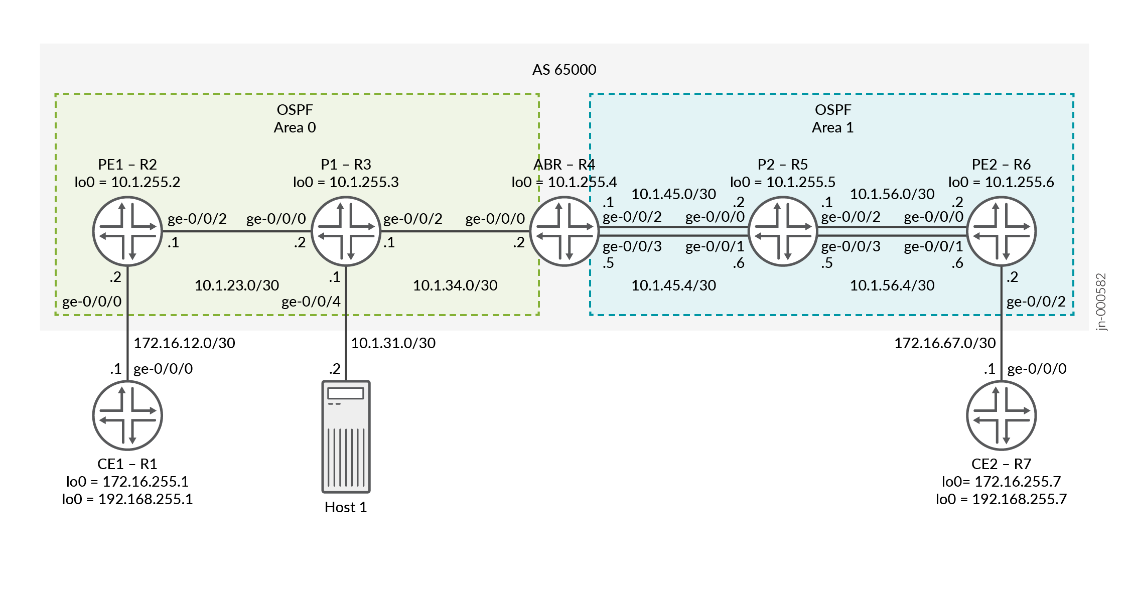
Topology
In Figure 3 , Router PE1 is the ingress router and Router PE2 is the egress router. Routers P1 and P2 are the transit routers. Router ABR is the area bridge router between Area 0 and Area 1. Two LSPs are configured on the ABR to PE2 for load balancing the traffic. Entropy label capability for BGP labeled unicast is enabled on the ingress Router PE1. Host 1 is connected to P1 for packet captures so that we can show the entropy label.
Configuration
- CLI Quick Configuration
- Configuring Router PE1
- Configuring Router P1
- Configuring Router ABR
- (Optional) Port-Mirroring Configuration
CLI Quick Configuration
To quickly configure this example, copy the following commands, paste them into a
text file, remove any line breaks, change any details necessary to match your
network configuration, copy and paste the commands into the CLI at the
[edit] hierarchy level, and then enter
commit from configuration mode.
Router CE1
set interfaces ge-0/0/0 unit 0 family inet address 172.16.12.1/30
set interfaces lo0 unit 0 family inet address 172.16.255.1/32 primary
set interfaces lo0 unit 0 family inet address 192.168.255.1/32
set routing-options router-id 172.16.255.1
set protocols ospf area 0.0.0.0 interface ge-0/0/0.0
set protocols ospf area 0.0.0.0 interface lo0.0 passive
Router PE1
set interfaces ge-0/0/0 unit 0 family inet address 172.16.12.2/30
set interfaces ge-0/0/2 unit 0 family inet address 10.1.23.1/30
set interfaces ge-0/0/2 unit 0 family mpls
set interfaces lo0 unit 0 family inet address 10.1.255.2/32 primary
set interfaces lo0 unit 1 family inet address 10.1.255.22/32
set policy-options policy-statement bgp-to-ospf from protocol bgp
set policy-options policy-statement bgp-to-ospf then accept
set policy-options policy-statement pplb then load-balance per-packet
set routing-instances VPN-l3vpn instance-type vrf
set routing-instances VPN-l3vpn protocols ospf area 0.0.0.0 interface ge-0/0/0.0
set routing-instances VPN-l3vpn protocols ospf area 0.0.0.0 interface lo0.1 passive
set routing-instances VPN-l3vpn protocols ospf export bgp-to-ospf
set routing-instances VPN-l3vpn interface ge-0/0/0.0
set routing-instances VPN-l3vpn interface lo0.1
set routing-instances VPN-l3vpn route-distinguisher 10.1.255.2:1
set routing-instances VPN-l3vpn vrf-target target:65000:1
set routing-options router-id 10.1.255.2
set routing-options autonomous-system 65000
set routing-options forwarding-table export pplb
set protocols bgp group ibgp type internal
set protocols bgp group ibgp local-address 10.1.255.2
set protocols bgp group ibgp family inet labeled-unicast entropy-label
set protocols bgp group ibgp neighbor 10.1.255.4 family inet labeled-unicast rib inet.3
set protocols bgp group ibgp neighbor 10.1.255.6 family inet-vpn unicast
set protocols mpls icmp-tunneling
set protocols mpls label-switched-path pe1-abr to 10.1.255.4
set protocols mpls label-switched-path pe1-abr entropy-label
set protocols mpls interface ge-0/0/2.0
set protocols mpls interface lo0.0
set protocols ospf traffic-engineering
set protocols ospf area 0.0.0.0 interface ge-0/0/2.0
set protocols ospf area 0.0.0.0 interface lo0.0 passive
set protocols rsvp interface ge-0/0/2.0
set protocols rsvp interface lo0.0
Router P1
set interfaces ge-0/0/0 unit 0 family inet address 10.1.23.2/30
set interfaces ge-0/0/0 unit 0 family mpls
set interfaces ge-0/0/2 unit 0 family inet address 10.1.34.1/30
set interfaces ge-0/0/2 unit 0 family mpls
set interfaces lo0 unit 0 family inet address 10.1.255.3/32 primary
set routing-options router-id 10.1.255.3
set protocols mpls icmp-tunneling
set protocols mpls interface ge-0/0/0.0
set protocols mpls interface lo0.0
set protocols mpls interface ge-0/0/2.0
set protocols ospf traffic-engineering
set protocols ospf area 0.0.0.0 interface lo0.0 passive
set protocols ospf area 0.0.0.0 interface ge-0/0/0.0
set protocols ospf area 0.0.0.0 interface ge-0/0/2.0
set protocols rsvp interface ge-0/0/0.0
set protocols rsvp interface lo0.0
set protocols rsvp interface ge-0/0/2.0
Router ABR
set interfaces ge-0/0/0 unit 0 family inet address 10.1.34.2/30
set interfaces ge-0/0/0 unit 0 family mpls
set interfaces ge-0/0/2 unit 0 family inet address 10.1.45.1/30
set interfaces ge-0/0/2 unit 0 family mpls
set interfaces ge-0/0/3 unit 0 family inet address 10.1.45.5/30
set interfaces ge-0/0/3 unit 0 family mpls
set interfaces lo0 unit 0 family inet address 10.1.255.4/32 primary
set forwarding-options hash-key family mpls label-1
set forwarding-options hash-key family mpls label-2
set forwarding-options hash-key family mpls label-3
set forwarding-options enhanced-hash-key family mpls no-payload
set policy-options policy-statement pplb then load-balance per-packet
set policy-options policy-statement send-inet3-pe1 from route-filter 10.1.255.2/32 exact
set policy-options policy-statement send-inet3-pe1 then accept
set policy-options policy-statement send-inet3-pe2 from route-filter 10.1.255.6/32 exact
set policy-options policy-statement send-inet3-pe2 then accept
set routing-options router-id 10.1.255.4
set routing-options autonomous-system 65000
set routing-options forwarding-table export pplb
set protocols bgp group ibgp type internal
set protocols bgp group ibgp local-address 10.1.255.4
set protocols bgp group ibgp family inet labeled-unicast rib inet.3
set protocols bgp group ibgp neighbor 10.1.255.2 export send-inet3-pe2
set protocols bgp group ibgp neighbor 10.1.255.6 export send-inet3-pe1
set protocols mpls icmp-tunneling
set protocols mpls label-switched-path abr-pe1 to 10.1.255.2
set protocols mpls label-switched-path abr-pe1 entropy-label
set protocols mpls label-switched-path abr-pe2 to 10.1.255.6
set protocols mpls label-switched-path abr-pe2 entropy-label
set protocols mpls label-switched-path abr-pe2 primary to-r6-1
set protocols mpls label-switched-path abr-pe2-2 to 10.1.255.6
set protocols mpls label-switched-path abr-pe2-2 entropy-label
set protocols mpls label-switched-path abr-pe2-2 primary to-r6-2
set protocols mpls path to-r6-1 10.1.45.2 strict
set protocols mpls path to-r6-1 10.1.56.2 strict
set protocols mpls path to-r6-2 10.1.45.6 strict
set protocols mpls path to-r6-2 10.1.56.6 strict
set protocols mpls interface lo0.0
set protocols mpls interface ge-0/0/0.0
set protocols mpls interface ge-0/0/2.0
set protocols mpls interface ge-0/0/3.0
set protocols ospf traffic-engineering
set protocols ospf area 0.0.0.0 interface lo0.0 passive
set protocols ospf area 0.0.0.0 interface ge-0/0/0.0
set protocols ospf area 0.0.0.1 interface ge-0/0/2.0
set protocols ospf area 0.0.0.1 interface ge-0/0/3.0
set protocols rsvp interface lo0.0
set protocols rsvp interface ge-0/0/0.0
set protocols rsvp interface ge-0/0/2.0
set protocols rsvp interface ge-0/0/3.0
Router P2
set interfaces ge-0/0/0 unit 0 family inet address 10.1.45.2/30
set interfaces ge-0/0/0 unit 0 family mpls
set interfaces ge-0/0/1 unit 0 family inet address 10.1.45.6/30
set interfaces ge-0/0/1 unit 0 family mpls
set interfaces ge-0/0/2 unit 0 family inet address 10.1.56.1/30
set interfaces ge-0/0/2 unit 0 family mpls
set interfaces ge-0/0/3 unit 0 family inet address 10.1.56.5/30
set interfaces ge-0/0/3 unit 0 family mpls
set interfaces lo0 unit 0 family inet address 10.1.255.5/32 primary
set forwarding-options hash-key family mpls label-1
set forwarding-options hash-key family mpls label-2
set forwarding-options hash-key family mpls label-3
set forwarding-options enhanced-hash-key family mpls no-payload
set policy-options policy-statement pplb then load-balance per-packet
set routing-options router-id 10.1.255.5
set routing-options forwarding-table export pplb
set protocols mpls icmp-tunneling
set protocols mpls interface ge-0/0/2.0
set protocols mpls interface lo0.0
set protocols mpls interface ge-0/0/0.0
set protocols mpls interface ge-0/0/1.0
set protocols mpls interface ge-0/0/3.0
set protocols ospf traffic-engineering
set protocols ospf area 0.0.0.1 interface lo0.0 passive
set protocols ospf area 0.0.0.1 interface ge-0/0/2.0
set protocols ospf area 0.0.0.1 interface ge-0/0/0.0
set protocols ospf area 0.0.0.1 interface ge-0/0/1.0
set protocols ospf area 0.0.0.1 interface ge-0/0/3.0
set protocols rsvp interface ge-0/0/2.0
set protocols rsvp interface lo0.0
set protocols rsvp interface ge-0/0/0.0
set protocols rsvp interface ge-0/0/1.0
set protocols rsvp interface ge-0/0/3.0
Router PE2
set interfaces ge-0/0/0 unit 0 family inet address 10.1.56.2/30
set interfaces ge-0/0/0 unit 0 family mpls
set interfaces ge-0/0/1 unit 0 family inet address 10.1.56.6/30
set interfaces ge-0/0/1 unit 0 family mpls
set interfaces ge-0/0/2 unit 0 family inet address 172.16.67.2/30
set interfaces lo0 unit 0 family inet address 10.1.255.6/32 primary
set interfaces lo0 unit 1 family inet address 10.1.255.66/32
set forwarding-options hash-key family mpls label-1
set forwarding-options hash-key family mpls label-2
set forwarding-options hash-key family mpls label-3
set forwarding-options enhanced-hash-key family mpls no-payload
set policy-options policy-statement bgp-to-ospf from protocol bgp
set policy-options policy-statement bgp-to-ospf then accept
set policy-options policy-statement pplb then load-balance per-packet
set routing-instances VPN-l3vpn instance-type vrf
set routing-instances VPN-l3vpn protocols ospf area 0.0.0.0 interface ge-0/0/2.0
set routing-instances VPN-l3vpn protocols ospf area 0.0.0.0 interface lo0.1 passive
set routing-instances VPN-l3vpn protocols ospf export bgp-to-ospf
set routing-instances VPN-l3vpn interface ge-0/0/2.0
set routing-instances VPN-l3vpn interface lo0.1
set routing-instances VPN-l3vpn route-distinguisher 10.1.255.6:1
set routing-instances VPN-l3vpn vrf-target target:65000:1
set routing-options router-id 10.1.255.6
set routing-options autonomous-system 65000
set routing-options forwarding-table export pplb
set protocols bgp group ibgp type internal
set protocols bgp group ibgp local-address 10.1.255.6
set protocols bgp group ibgp family inet labeled-unicast entropy-label
set protocols bgp group ibgp neighbor 10.1.255.4 family inet labeled-unicast rib inet.3
set protocols bgp group ibgp neighbor 10.1.255.2 family inet-vpn unicast
set protocols mpls icmp-tunneling
set protocols mpls label-switched-path pe2-abr to 10.1.255.4
set protocols mpls label-switched-path pe2-abr entropy-label
set protocols mpls interface ge-0/0/0.0
set protocols mpls interface lo0.0
set protocols mpls interface ge-0/0/1.0
set protocols ospf traffic-engineering
set protocols ospf area 0.0.0.1 interface ge-0/0/0.0
set protocols ospf area 0.0.0.1 interface lo0.0 passive
set protocols ospf area 0.0.0.1 interface ge-0/0/1.0
set protocols rsvp interface ge-0/0/0.0
set protocols rsvp interface lo0.0
set protocols rsvp interface ge-0/0/1.0
Router CE2
set interfaces ge-0/0/0 unit 0 family inet address 172.16.67.1/30
set interfaces lo0 unit 0 family inet address 172.16.255.7/32 primary
set interfaces lo0 unit 0 family inet address 192.168.255.7/32
set routing-options router-id 172.16.255.7
set protocols ospf area 0.0.0.0 interface ge-0/0/0.0
set protocols ospf area 0.0.0.0 interface lo0.0 passive
Configuring Router PE1
Step-by-Step Procedure
The following example requires that you navigate various levels in the configuration hierarchy. For information about navigating the CLI, see Using the CLI Editor in Configuration Mode in the CLI User Guide.
To configure Router PE1:
Repeat this procedure for Router PE2 after modifying the appropriate interface names, addresses, and other parameters.
-
Configure the physical interfaces. Ensure to configure
family mplson the core facing interface.[edit] user@PE1# set interfaces ge-0/0/0 unit 0 family inet address 172.16.12.2/30 user@PE1# set interfaces ge-0/0/2 unit 0 family inet address 10.1.23.1/30 user@PE1# set interfaces ge-0/0/2 unit 0 family mpls
-
Configure the loopback interfaces. The secondary loopback is optional and is applied under the routing instance in a later step.
[edit]
user@PE1# set interfaces lo0 unit 0 family inet address 10.1.255.2/32 primary
user@PE1# set interfaces lo0 unit 1 family inet address 10.1.255.22/32
-
Configure the router ID and the autonomous system number.
[edit]
user@PE1# set routing-options router-id 10.1.255.2
user@PE1# set routing-options autonomous-system 65000
-
Configure the OSPF protocol.
[edit]
user@PE1# set protocols ospf traffic-engineering
user@PE1# set protocols ospf area 0.0.0.0 interface ge-0/0/2.0
user@PE1# set protocols ospf area 0.0.0.0 interface lo0.0 passive
-
Configure the RSVP protocol.
[edit]
user@PE1# set protocols rsvp interface ge-0/0/2.0
user@PE1# set protocols rsvp interface lo0.0
-
Configure the MPLS protocol and an LSP towards the ABR. Include the
entropy-labeloption to add the entropy label to the MPLS label stack.[edit protocols] user@PE1# set protocols mpls icmp-tunneling user@PE1# set protocols mpls label-switched-path pe1-abr to 10.1.255.4 user@PE1# set protocols mpls label-switched-path pe1-abr entropy-label user@PE1# set protocols mpls interface ge-0/0/2.0 user@PE1# set protocols mpls interface lo0.0
-
Configure IBGP using
family inet labeled-unicastfor the ABR peering andfamily inet-vpnfor the PE2 peering. Enable entropy label capability for BGP labeled unicast.[edit] user@PE1# set protocols bgp group ibgp type internal user@PE1# set protocols bgp group ibgp local-address 10.1.255.2 user@PE1# set protocols bgp group ibgp family inet labeled-unicast entropy-label user@PE1# set protocols bgp group ibgp neighbor 10.1.255.4 family inet labeled-unicast rib inet.3 user@PE1# set protocols bgp group ibgp neighbor 10.1.255.6 family inet-vpn unicast
-
Define a policy to export BGP VPN routes into OSPF. The policy is applied under OSPF in the routing instance.
[edit]
user@PE1# set policy-options policy-statement bgp-to-ospf from protocol bgp
user@PE1# set policy-options policy-statement bgp-to-ospf then accept
-
Define a load balancing policy and apply it under the
routing-options
                                    forwarding-table
. PE1 only has one path in the example therefore this step is not needed, but for this example we are applying the same load balancing policy on all devices.[edit] user@PE1# set policy-options policy-statement pplb then load-balance per-packet user@PE1# set routing-options forwarding-table export pplb
-
Configure the Layer 3 VPN routing instance.
[edit]
user@PE1# set routing-instances VPN-l3vpn instance-type vrf
-
Assign the interfaces to the routing instance.
[edit]
user@PE1# set routing-instances VPN-l3vpn interface ge-0/0/0.0
user@PE1# set routing-instances VPN-l3vpn interface lo0.1
-
Configure the route distinguisher for the routing instance.
[edit]
user@PE1# set routing-instances VPN-l3vpn route-distinguisher 10.1.255.2:1
-
Configure a VPN routing and forwarding (VRF) target for the routing instance.
[edit]
user@PE1# set routing-instances VPN-l3vpn vrf-target target:65000:1
-
Configure the protocol OSPF under the routing instance and apply the previously configured
bgp-to-ospfpolicy.[edit] user@PE1# set routing-instances VPN-l3vpn protocols ospf area 0.0.0.0 interface ge-0/0/0.0 user@PE1# set routing-instances VPN-l3vpn protocols ospf area 0.0.0.0 interface lo0.1 passive user@PE1# set routing-instances VPN-l3vpn protocols ospf export bgp-to-ospf
Configuring Router P1
Step-by-Step Procedure
The following example requires that you navigate various levels in the configuration hierarchy. For information about navigating the CLI, see Using the CLI Editor in Configuration Mode in the CLI User Guide.
To configure Router P1:
Repeat this procedure for Router P2 after modifying the appropriate interface names, addresses, and other parameters.
-
Configure the physical interfaces.
[edit]
user@P1# set interfaces ge-0/0/0 unit 0 family inet address 10.1.23.2/30
user@P1# set interfaces ge-0/0/0 unit 0 family mpls
user@P1# set interfaces ge-0/0/2 unit 0 family inet address 10.1.34.1/30
user@P1# set interfaces ge-0/0/2 unit 0 family mpls
-
Configure the loopback interface.
[edit]
user@P1# set interfaces lo0 unit 0 family inet address 10.1.255.3/32 primary
-
Configure the router ID.
[edit]
user@P1# set routing-options router-id 10.1.255.3
-
Configure the OSPF protocol.
[edit]
user@P1# set protocols ospf traffic-engineering
user@P1# set protocols ospf area 0.0.0.0 interface lo0.0 passive
user@P1# set protocols ospf area 0.0.0.0 interface ge-0/0/0.0
user@P1# set protocols ospf area 0.0.0.0 interface ge-0/0/2.0
-
Configure the RSVP protocol.
[edit]
user@P1# set protocols rsvp interface ge-0/0/0.0
user@P1# set protocols rsvp interface lo0.0
user@P1# set protocols rsvp interface ge-0/0/2.0
-
Configure the MPLS protocol.
[edit]
user@P1# set protocols mpls icmp-tunneling
user@P1# set protocols mpls interface ge-0/0/0.0
user@P1# set protocols mpls interface lo0.0
user@P1# set protocols mpls interface ge-0/0/2.0
Configuring Router ABR
Step-by-Step Procedure
The following example requires that you navigate various levels in the configuration hierarchy. For information about navigating the CLI, see Using the CLI Editor in Configuration Mode in the CLI User Guide.
To configure Router ABR:
-
Configure the physical interfaces.
[edit]
user@ABR# set interfaces ge-0/0/0 unit 0 family inet address 10.1.34.2/30
user@ABR# set interfaces ge-0/0/0 unit 0 family mpls
user@ABR# set interfaces ge-0/0/2 unit 0 family inet address 10.1.45.1/30
user@ABR# set interfaces ge-0/0/2 unit 0 family mpls
user@ABR# set interfaces ge-0/0/3 unit 0 family inet address 10.1.45.5/30
user@ABR# set interfaces ge-0/0/3 unit 0 family mpls
-
Configure the loopback interface.
[edit]
user@ABR# set interfaces lo0 unit 0 family inet address 10.1.255.4/32 primary
-
Configure MPLS labels that the router uses for hashing the packets to its destination for load balancing.
[edit]
user@ABR# set forwarding-options hash-key family mpls label-1
user@ABR# set forwarding-options hash-key family mpls label-2
user@ABR# set forwarding-options hash-key family mpls label-3
user@ABR# set forwarding-options enhanced-hash-key family mpls no-payload
-
Configure the router ID and the autonomous system number.
[edit]
user@ABR# set routing-options router-id 10.1.255.4
user@ABR# set routing-options autonomous-system 65000
-
Configure the OSPF protocol.
[edit]
user@ABR# set protocols ospf traffic-engineering
user@ABR# set protocols ospf area 0.0.0.0 interface lo0.0 passive
user@ABR# set protocols ospf area 0.0.0.0 interface ge-0/0/0.0
user@ABR# set protocols ospf area 0.0.0.1 interface ge-0/0/2.0
user@ABR# set protocols ospf area 0.0.0.1 interface ge-0/0/3.0
-
Configure the RSVP protocol.
[edit]
user@ABR# set protocols rsvp interface lo0.0
user@ABR# set protocols rsvp interface ge-0/0/0.0
user@ABR# set protocols rsvp interface ge-0/0/2.0
user@ABR# set protocols rsvp interface ge-0/0/3.0
-
Configure the MPLS protocol and specify the LSPs towards PE1 and PE2. Two LSPs are created towards PE2 for the purpose of load balancing traffic to show different LSPs and interfaces are used.
[edit]
user@ABR# set protocols mpls icmp-tunneling
user@ABR# set protocols mpls label-switched-path abr-pe1 to 10.1.255.2
user@ABR# set protocols mpls label-switched-path abr-pe1 entropy-label
user@ABR# set protocols mpls label-switched-path abr-pe2 to 10.1.255.6
user@ABR# set protocols mpls label-switched-path abr-pe2 entropy-label
user@ABR# set protocols mpls label-switched-path abr-pe2 primary to-r6-1
user@ABR# set protocols mpls label-switched-path abr-pe2-2 to 10.1.255.6
user@ABR# set protocols mpls label-switched-path abr-pe2-2 entropy-label
user@ABR# set protocols mpls label-switched-path abr-pe2-2 primary to-r6-2
user@ABR# set protocols mpls path to-r6-1 10.1.45.2 strict
user@ABR# set protocols mpls path to-r6-1 10.1.56.2 strict
user@ABR# set protocols mpls path to-r6-2 10.1.45.6 strict
user@ABR# set protocols mpls path to-r6-2 10.1.56.6 strict
user@ABR# set protocols mpls interface lo0.0
user@ABR# set protocols mpls interface ge-0/0/0.0
user@ABR# set protocols mpls interface ge-0/0/2.0
user@ABR# set protocols mpls interface ge-0/0/3.0
-
Configure IBGP to both PE1 and PE2 using
family inet
                                labeled-unicast
. Apply the policy to advertise the inet.3 loopback route from both PE1 and PE2. We show the policy in the next step.[edit] user@ABR# set protocols bgp group ibgp type internal user@ABR# set protocols bgp group ibgp local-address 10.1.255.4 user@ABR# set protocols bgp group ibgp family inet labeled-unicast rib inet.3 user@ABR# set protocols bgp group ibgp neighbor 10.1.255.2 export send-inet3-pe2 user@ABR# set protocols bgp group ibgp neighbor 10.1.255.6 export send-inet3-pe1
-
Define a policy to match on the loopback addresses for PE1 and PE2.
[edit]
user@ABR# set policy-options policy-statement send-inet3-pe1 from route-filter 10.1.255.2/32 exact
user@ABR# set policy-options policy-statement send-inet3-pe1 then accept
user@ABR# set policy-options policy-statement send-inet3-pe2 from route-filter 10.1.255.6/32 exact
user@ABR# set policy-options policy-statement send-inet3-pe2 then accept
-
Define a policy for load balancing and apply it under the
routing-options forwarding-table.[edit] user@ABR# set policy-options policy-statement pplb then load-balance per-packet user@ABR# set routing-options forwarding-table export pplb
(Optional) Port-Mirroring Configuration
To see the entropy label that is applied you can capture the traffic. In this example a filter is applied on the PE1 facing interface on P1 to capture the CE1 to CE2 traffic. The traffic is sent to Host 1 for viewing. There are different ways to capture traffic than what we use in this example. For more information see Understanding Port Mirroring and Analyzers.
Step-by-Step Procedure
The following example requires that you navigate various levels in the configuration hierarchy. For information about navigating the CLI, see Using the CLI Editor in Configuration Mode in the CLI User Guide.
To configure Router P1:
-
Configure the interfaces. In this example we are putting the interface connected to Host1 in a bridge domain and creating an IRB interface for verifying connectivity to Host1.
[edit]
user@P1# set interfaces ge-0/0/4 unit 0 family bridge interface-mode access
user@P1# set interfaces ge-0/0/4 unit 0 family bridge vlan-id 100
user@P1# set interfaces irb unit 0 family inet address 10.1.31.1/30
-
Configure the bridge domain.
[edit]
user@P1# set bridge-domains v100 vlan-id 100
user@P1# set bridge-domains v100 routing-interface irb.0
-
Configure a filter to capture the traffic. For this example we are capturing all traffic.
[edit]
user@P1# set firewall family any filter test term 1 then count test
user@P1# set firewall family any filter test term 1 then port-mirror
user@P1# set firewall family any filter test term 1 then accept
-
Apply the filter to the PE1 facing interface.
[edit]
user@P1# set interfaces ge-0/0/0 unit 0 filter input test
-
Configure the port mirroring options. For this example we are mirroring all traffic and sending it to Host1 connected to interface ge-0/0/4.
[edit]
user@P1# set forwarding-options port-mirroring input rate 1
user@P1# set forwarding-options port-mirroring family any output interface ge-0/0/4.0
Verification
Confirm that the configuration is working properly.
- Verifying That the Entropy Label Capability Is Being Advertised
- Verifying That Router PE1 Receives the Entropy Label Advertisement
- Verifying ECMP at the ABR to PE2
- Show Routes to CE2 on PE1
- Ping CE2 from CE1
- Verify Load Balancing
- Verify the Entropy Label
Verifying That the Entropy Label Capability Is Being Advertised
Purpose
Verify that the entropy label capability path attribute is being advertised from the ABR to PE1 for the route to PE2.
Action
From operational mode, run the show route advertising-protocol bgp 10.1.255.2 detail command on Router ABR.
user@ABR> show route advertising-protocol bgp 10.1.255.2 detail

inet.3: 2 destinations, 2 routes (2 active, 0 holddown, 0 hidden)
* 10.1.255.6/32 (1 entry, 1 announced)
 BGP group ibgp type Internal
     Route Label: 299952
     Nexthop: Self
     Flags: Nexthop Change
     MED: 2
     Localpref: 4294967294
     AS path: [65000] I
     Entropy label capable
Meaning
The output shows that the host PE2 with the IP address of 10.1.255.6 has the entropy label capability and the route label that is used. The host is advertising the entropy label capability to its BGP neighbors.
Verifying That Router PE1 Receives the Entropy Label Advertisement
Purpose
Verify that Router PE1 receives the entropy label advertisement for Router PE2.
Action
From operational mode, run the show route protocol bgp 10.1.255.6 extensive command on Router PE1.
user@PE1> show route protocol bgp 10.1.255.6 extensive

inet.0: 19 destinations, 19 routes (19 active, 0 holddown, 0 hidden)

inet.3: 2 destinations, 2 routes (2 active, 0 holddown, 0 hidden)
10.1.255.6/32 (1 entry, 1 announced)
        *BGP    Preference: 170/1
                Next hop type: Indirect, Next hop index: 0
                Address: 0x7b3ffd4
                Next-hop reference count: 2, key opaque handle: 0x0, non-key opaque handle: 0x0
                Source: 10.1.255.4
                Next hop type: Router, Next hop index: 0
                Next hop: 10.1.23.2 via ge-0/0/2.0, selected
                Label-switched-path pe1-abr
                Label operation: Push 299952, Push 299808(top)
                Label TTL action: prop-ttl, prop-ttl(top)
                Load balance label: Label 299952: Entropy label; Label 299808: None;
                Label element ptr: 0x93d6bf8
                Label parent element ptr: 0x93d6c20
                Label element references: 3
                Label element child references: 2
                Label element lsp id: 0
                Session Id: 0
                Protocol next hop: 10.1.255.4
                Label operation: Push 299952
                Label TTL action: prop-ttl
                Load balance label: Label 299952: Entropy label;
                Indirect next hop: 0x758c05c - INH Session ID: 0
                State: <Active Int Ext>
                Local AS: 65000 Peer AS: 65000
                Age: 1:33:11    Metric: 2       Metric2: 2
                Validation State: unverified
                Task: BGP_65000.10.1.255.4
                Announcement bits (2): 3-Resolve tree 1 4-Resolve_IGP_FRR task
                AS path: I
                Accepted
                Route Label: 299952
                Localpref: 4294967294
                Router ID: 10.1.255.4
                Session-IDs associated:
                Session-id: 324 Version: 3
                Thread: junos-main
                Indirect next hops: 1
                        Protocol next hop: 10.1.255.4 Metric: 2 ResolvState: Resolved
                        Label operation: Push 299952
                        Label TTL action: prop-ttl
                        Load balance label: Label 299952: Entropy label;
                        Indirect next hop: 0x758c05c - INH Session ID: 0
                        Indirect path forwarding next hops: 1
                                Next hop type: Router
                                Next hop: 10.1.23.2 via ge-0/0/2.0
                                Session Id: 0
                                10.1.255.4/32 Originating RIB: inet.3
                                  Metric: 2 Node path count: 1
                                  Forwarding nexthops: 1
                                        Next hop type: Router
                                        Next hop: 10.1.23.2 via ge-0/0/2.0
                                        Session Id: 0
Meaning
Router PE1 receives the entropy label capability advertisement from its BGP neighbor.
Verifying ECMP at the ABR to PE2
Purpose
Verify equal-cost multipath (ECMP) to PE2.
Action
From operational mode, run the show route table mpls.0 and show route forwarding-table label <label>commands on Router ABR.
user@ABR> show route table mpls.0

mpls.0: 6 destinations, 6 routes (6 active, 0 holddown, 0 hidden)
+ = Active Route, - = Last Active, * = Both

0                  *[MPLS/0] 2w1d 23:02:11, metric 1
                       Receive
1                  *[MPLS/0] 2w1d 23:02:11, metric 1
                       Receive
2                  *[MPLS/0] 2w1d 23:02:11, metric 1
                       Receive
13                 *[MPLS/0] 2w1d 23:02:11, metric 1
                       Receive
299936             *[VPN/170] 2d 21:47:02
                    >  to 10.1.34.1 via ge-0/0/0.0, label-switched-path abr-pe1
299952             *[VPN/170] 2d 21:47:02
                    >  to 10.1.45.2 via ge-0/0/2.0, label-switched-path abr-pe2
                       to 10.1.45.6 via ge-0/0/3.0, label-switched-path abr-pe2-2

ruser@ABR> show route forwarding-table label 299952
Routing table: default.mpls
MPLS:
Destination        Type RtRef Next hop           Type Index    NhRef Netif
299952             user     0                    ulst  1048575     2
                              10.1.45.2         Swap 299824      516     2 ge-0/0/2.0
                              10.1.45.6         Swap 299840      572     2 ge-0/0/3.0
...
Meaning
The output shows an ECMP for the label used for the BGP labeled unicast route.
Show Routes to CE2 on PE1
Purpose
Verify the routes to CE2.
Action
From operational mode, run the show route table VPN-l3vpn.inet.0 172.16.255.7 extensive and show route table VPN-l3vpn.inet.0 192.168.255.7 extensivecommands on Router PE1.
user@PE1> show route table VPN-l3vpn.inet.0 172.16.255.7 extensive

VPN-l3vpn.inet.0: 10 destinations, 10 routes (10 active, 0 holddown, 0 hidden)
172.16.255.7/32 (1 entry, 1 announced)
TSI:
OSPF area : 0.0.0.0, LSA ID : 172.16.255.7, LSA type : Summary
KRT in-kernel 172.16.255.7/32 -> {indirect(1048574)}
        *BGP    Preference: 170/-101
                Route Distinguisher: 10.1.255.6:1
                Next hop type: Indirect, Next hop index: 0
                Address: 0x7b40434
                Next-hop reference count: 9, key opaque handle: 0x0, non-key opaque handle: 0x0
                Source: 10.1.255.6
                Next hop type: Router, Next hop index: 515
                Next hop: 10.1.23.2 via ge-0/0/2.0, selected
                Label-switched-path pe1-abr
                Label operation: Push 299824, Push 299952, Push 299808(top)
                Label TTL action: prop-ttl, prop-ttl, prop-ttl(top)
                Load balance label: Label 299824: None; Label 299952: Entropy label; Label 299808: None;
                Label element ptr: 0x93d6c98
                Label parent element ptr: 0x93d6bf8
                Label element references: 1
                Label element child references: 0
                Label element lsp id: 0
                Session Id: 140
                Protocol next hop: 10.1.255.6
                Label operation: Push 299824
                Label TTL action: prop-ttl
                Load balance label: Label 299824: None;
...

user@PE1> show route table VPN-l3vpn.inet.0 192.168.255.7 extensive
VPN-l3vpn.inet.0: 10 destinations, 10 routes (10 active, 0 holddown, 0 hidden)
192.168.255.7/32 (1 entry, 1 announced)
TSI:
OSPF area : 0.0.0.0, LSA ID : 192.168.255.7, LSA type : Summary
KRT in-kernel 192.168.255.7/32 -> {indirect(1048574)}
        *BGP    Preference: 170/-101
                Route Distinguisher: 10.1.255.6:1
                Next hop type: Indirect, Next hop index: 0
                Address: 0x7b40434
                Next-hop reference count: 9, key opaque handle: 0x0, non-key opaque handle: 0x0
                Source: 10.1.255.6
                Next hop type: Router, Next hop index: 515
                Next hop: 10.1.23.2 via ge-0/0/2.0, selected
                Label-switched-path pe1-abr
                Label operation: Push 299824, Push 299952, Push 299808(top)
                Label TTL action: prop-ttl, prop-ttl, prop-ttl(top)
                Load balance label: Label 299824: None; Label 299952: Entropy label; Label 299808: None;
                Label element ptr: 0x93d6c98
                Label parent element ptr: 0x93d6bf8
                Label element references: 1
                Label element child references: 0
                Label element lsp id: 0
                Session Id: 140
                Protocol next hop: 10.1.255.6
                Label operation: Push 299824
                Label TTL action: prop-ttl
                Load balance label: Label 299824: None;
...
Meaning
The output shows the same labels are used for both routes.
Ping CE2 from CE1
Purpose
Verify connectivity and to use for verifying load balancing.
Action
From operational mode, run the ping 172.16.255.7 source 172.16.12.1 rapid count 100 and ping 192.168.255.7 source 192.168.255.1 rapid count 200commands on Router PE1.
user@CE1> ping 172.16.255.7 source 172.16.12.1 rapid count 100
PING 172.16.255.7 (172.16.255.7): 56 data bytes
!!!!!!!!!!!!!!!!!!!!!!!!!!!!!!!!!!!!!!!!!!!!!!!!!!!!!!!!!!!!!!!!!!!!!!!!!!!!!!!!!!!!!!!!!!!!!!!!!!!!
--- 172.16.255.7 ping statistics ---
100 packets transmitted, 100 packets received, 0% packet loss
round-trip min/avg/max/stddev = 5.369/6.070/8.828/0.612 ms

user@CE1> ping 192.168.255.7 source 192.168.255.1 rapid count 200
PING 192.168.255.7 (192.168.255.7): 56 data bytes
!!!!!!!!!!!!!!!!!!!!!!!!!!!!!!!!!!!!!!!!!!!!!!!!!!!!!!!!!!!!!!!!!!!!!!!!!!!!!!!!!!!!!!!!!!!!!!!!!!!!!!!!!!!!!!!!!!!!!!!!!!!!!!!!!!!!!!!!!!!!!!!!!!!!!!!!!!!!!!!!!!!!!!!!!!!!!!!!!!!!!!!!!!!!!!!!!!!!!!!!
--- 192.168.255.7 ping statistics ---
200 packets transmitted, 200 packets received, 0% packet loss
round-trip min/avg/max/stddev = 5.086/5.994/10.665/0.649 ms
Meaning
The output shows pings are successful.
Verify Load Balancing
Purpose
Verify load balancing.
Action
From operational mode, run the show mpls lsp ingress statistics command on the ABR.
user@ABR> show mpls lsp ingress statistics
Ingress LSP: 3 sessions
To              From            State     Packets            Bytes LSPname
10.1.255.2      10.1.255.4      Up            300            30000 abr-pe1
10.1.255.6      10.1.255.4      Up            200            20000 abr-pe2
10.1.255.6      10.1.255.4      Up            100            10000 abr-pe2-2
Total 3 displayed, Up 3, Down 0
Meaning
The output shows the first ping from the previous command used LSP abr-pe2-2 and the second ping used LSP abr-pe2.
Verify the Entropy Label
Purpose
Verify the entropy label is different between the pings that were used.
Action
On Host 1, run the tcpdump -i eth1 -n.
user@Host1# tcpdump -i eth1 -n
...
13:42:31.993274 MPLS (label 299808, exp 0, ttl 63) (label 299952, exp 0, ttl 63) (label 7, exp 0, ttl 63) (label 1012776, exp 0, ttl 0)
(label 299824, exp 0, [S], ttl 63) IP 172.16.12.1 > 172.16.255.7: ICMP echo request, id 32813, seq 9, length 64
...
13:43:19.570260 MPLS (label 299808, exp 0, ttl 63) (label 299952, exp 0, ttl 63) (label 7, exp 0, ttl 63) (label 691092, exp 0, ttl 0)
(label 299824, exp 0, [S], ttl 63) IP 192.168.255.1 > 192.168.255.7: ICMP echo request, id 46381, seq 9, length 64
Meaning
The output shows the different value for the entropy label for the two different ping commands.
Configuring Ultimate-Hop Popping for LSPs
By default, RSVP-signaled LSPs use penultimate-hop popping (PHP). Figure 4 illustrates a penultimate-hop popping LSP between Router PE1 and Router PE2. Router CE1 forwards a packet to its next hop (Router PE1), which is also the LSP ingress. Router PE1 pushes label 1 on the packet and forwards the labeled packet to Router P1. Router P1 completes the standard MPLS label swapping operation, swapping label 1 for label 2, and forwards the packet to Router P2. Since Router P2 is the penultimate-hop router for the LSP to Router PE2, it first pops the label and then forwards the packet to Router PE2. When Router PE2 receives it, the packet can have a service label, an explicit-null label, or just be a plain IP or VPLS packet. Router PE2 forwards the unlabeled packet to Router CE2.
You can also configure ultimate-hop popping (UHP) (as shown in Figure 5) for RSVP-signaled LSPs. Some network applications can require that packets arrive at the egress router (Router PE2) with a non-null outer label. For an ultimate- hop popping LSP, the penultimate router (Router P2 in Figure 5) performs the standard MPLS label swapping operation (in this example, label 2 for label 3 ) before forwarding the packet to egress Router PE2. Router PE2 pops the outer label and performs a second lookup of the packet address to determine the end destination. It then forwards the packet to the appropriate destination (either Router CE2 or Router CE4).
The following network applications require that you configure UHP LSPs:
MPLS-TP for performance monitoring and in-band OAM
Edge protection virtual circuits
The following features do not support the UHP behavior:
LDP-signaled LSPs
Static LSPs
Point-to-multipoint LSPs
CCC
traceroutecommand
For more information about UHP behavior, see Internet draft draft-ietf-mpls-rsvp-te-no-php-oob-mapping-01.txt, Non PHP behavior and Out-of-Band Mapping for RSVP-TE LSPs.
For point-to-point RSVP-signaled LSPs, UHP behavior is signaled from the LSP ingress. Based on the ingress router configuration, RSVP can signal the UHP LSP with the non-PHP flag set. RSVP PATH messages carry the two flags in the LSP-ATTRIBUTES object. When the egress router receives the PATH message, it assigns a non-null label to the LSP. RSVP also creates and installs two routes in the mpls.0 routing table. S refers to the S bit of the MPLS label, which indicates whether or not the bottom of the label stack has been reached.
Route S=0—Indicates that there are more labels in the stack. The next hop for this route points to the mpls.0 routing table, triggering a chained MPLS label lookup to discover the remaining MPLS labels in the stack.
Route S=1—Indicates that there are no more labels. The next hop points to the inet.0 routing table if the platform supports chained and multi-family lookup. Alternatively, the label route can point to a VT interface to initiate IP forwarding.
If you enable UHP LSPs, MPLS applications such as Layer 3 VPNs, VPLS, Layer 2 VPNs, and Layer 2 circuits can use the UHP LSPs. The following explains how UHP LSPs affect the different types of MPLS applications:
Layer 2 VPNs and Layer 2 circuits—A packet arrives at the PE router (egress of the UHP LSP) with two labels. The outer label (S=0) is the UHP label, and the inner label (S=1) is the VC label. A lookup based on the transport label results in a table handle for the mpls.0 routing table. There is an additional route in the mpls.0 routing table corresponding to the inner label. A lookup based on the inner label results in the CE router next hop.
Layer 3 VPN—A packet arrives at the PE router (egress of the UHP LSP) with two labels. The outer label (S=0) is the UHP label, and the inner label is the VPN label (S=1). A lookup based on the transport label results in the table handle for the mpls.0 routing table. There are two cases in this scenario. By default, Layer 3 VPNs advertise the per-next hop label. A lookup based on the inner label results in the next hop toward the CE router. However, if you have configured the
vrf-table-labelstatement for the Layer 3 VPN routing instance, the inner LSI label points to the VRF routing table. An IP lookup is also completed for the VRF routing table.Note:UHP for Layer 3 VPNs configured with the
vrf-table-labelstatement is supported on MX Series 5G Universal Routing Platforms only.VPLS—A packet arrives at the PE router (egress of the UHP LSP) with two labels. The outer label is the transport label (S=0) and the inner label is the VPLS label (S=1). A lookup based on the transport label results in the table handle for the mpls.0 routing table. A lookup based on the inner label in mpls.0 routing table results in the LSI tunnel interface of the VPLS routing instance if tunnel-services is not configured (or a VT interface not available). MX 3D Series routers support chained lookup and multi-family lookup.
Note:UHP for VPLS configured with the
no-tunnel-servicestatement is supported on MX 3D Series routers only.IPv4 over MPLS—A packet arrives at the PE router (egress of the UHP LSP) with one label (S=1). A lookup based on this label returns a VT tunnel interface. Another IP lookup is completed on the VT interface to determine where to forward the packet. If the routing platform supports multi-family and chained lookups (for example, MX 3D routers and PTX Series Packet Transport Routers), lookup based on label route (S=1) points to the inet.0 routing table.
IPv6 over MPLS—For IPv6 tunneling over MPLS, PE routers advertise IPv6 routes to each other with a label value of 2. This is the explicit null label for IPv6. As a result, the forwarding next hops for IPv6 routes that are learned from remote PE routers normally push two labels. The inner label is 2 (it could be different if the advertising PE router is from another vendor), and the router label is the LSP label. Packets arrive at the PE router (egress of the UHP LSP) with two labels. The outer label is the transport label (S=0), and the inner label is the IPv6 explicit-null label (label 2). Lookup based on the inner label in the mpls.0 routing table redirects back to the mpls.0 routing table. On MX 3D Series routers, the inner label (label 2) is stripped off and an IPv6 lookup is done using the inet6.0 routing table.
Enabling both PHP and UHP LSPs—You can configure both PHP and UHP LSPs over the same network paths. You can separate PHP and UHP traffic by selecting forwarding LSP next hops using a regular expression with the
install-nexthopstatement. You can also separate traffic by simply naming the LSPs appropriately.
The following statements enable ultimate-hop popping for an LSP. You can enable this feature on a specific LSP or for all of the ingress LSPs configured on the router. Configure these statements on the router at the LSP ingress.
Configuring Explicit-Path LSPs
If you disable constrained-path label-switched path (LSP) computation, as described in Disabling Constrained-Path LSP Computation, you can configure LSPs manually or allow the LSPs to follow the IGP path.
When explicit-path LSPs are configured, the LSP is established along the path you specified. If the path is topologically not feasible, either because the network is partitioned or insufficient resources are available along some parts of the path, the LSP will fail. No alternative paths can be used. If the setup succeeds, the LSP stays on the defined path indefinitely.
To configure an explicit-path LSP, follow these steps:
-
Configure the path information in a named path, as described in Creating Named Paths. To configure complete path information, specify every router hop between the ingress and egress routers, preferably using the
strictattribute. To configure incomplete path information, specify only a subset of router hops, using thelooseattribute in places where the path is incomplete.For incomplete paths, the MPLS routers complete the path by querying the local routing table. This query is done on a hop-by-hop basis, and each router can figure out only enough information to reach the next explicit hop. It might be necessary to traverse a number of routers to reach the next (loose) explicit hop.
Configuring incomplete path information creates portions of the path that depend on the current routing table, and this portion of the path can reroute itself as the topology changes. Therefore, an explicit-path LSP that contains incomplete path information is not completely fixed. These types of LSPs have only a limited ability to repair themselves, and they tend to create loops or flaps depending on the contents of the local routing table.
-
To configure the LSP and point it to the named path, use either the
primaryorsecondarystatement, as described in Configuring Primary and Secondary LSPs. -
Disable constrained-path LSP computation by including the
no-cspfstatement either as part of the LSP or as part of aprimaryorsecondarystatement. For more information, see Disabling Constrained-Path LSP Computation. -
Configure any other LSP properties.
When defining a constrained path LSP using more than one strict hop belonging to the egress node, the first strict hop must be set to match the IP address assigned to the egress node on the interface that receives the RSVP Path message. If the incoming RSVP Path message arrives on an interface with a different IP address the LSP is rejected.
Prior to Junos OS 20.3X75-D20 or 22.2R1, any additional strict hop after the strict hop matching the IP address of the interface that receives the RSVP Path message must be set to match a loopback address assigned to the egress node. In later Junos releases this behavior is changed to permit an additional strict hop that matches an IP address assigned to any interface on the egress node
Using explicit-path LSPs has the following drawbacks:
-
More configuration effort is required.
-
Configured path information cannot take into account dynamic network bandwidth reservation, so the LSPs tend to fail when resources become depleted.
-
When an explicit-path LSP fails, you might need to manually repair it.
Because of these limitations, we recommend that you use explicit-path LSPs only in controlled situations, such as to enforce an optimized LSP placement strategy resulting from computations with an offline simulation software package.
Example: Configuring an Explicit-Path LSP
On the ingress router, create an explicit-path LSP, and specify the transit routers between the ingress and egress routers. In this configuration, no constrained-path computation is performed. For the primary path, all intermediate hops are strictly specified so that its route cannot change. The secondary path must travel through router 14.1.1.1 first, then take whatever route is available to reach the destination. The remaining route taken by the secondary path is typically the shortest path computed by the IGP.
When defining a constrained path LSP using more than one strict hop belonging to the egress node, the first strict hop must be set to match the IP address assigned to the egress node on the interface that receives the RSVP Path message. If the incoming RSVP Path message arrives on an interface with a different IP address the LSP is rejected.
Prior to Junos OS 20.3X75-D20 or 22.2R1, any additional strict hop after the strict hop matching the IP address of the interface that receives the RSVP Path message must be set to match a loopback address assigned to the egress node. In later Junos releases this behavior is changed to permit an additional strict hop that matches an IP address assigned to any interface on the egress node
[edit]
interfaces {
    so-0/0/0 {
        unit 0 {
            family mpls;
        }
    }
}
protocols {
    rsvp {
        interface so-0/0/0;
    }
    mpls {
        path to-hastings {
            14.1.1.1 strict;
            13.1.1.1 strict;
            12.1.1.1 strict;
            11.1.1.1 strict;
        }
        path alt-hastings {
            14.1.1.1 strict;
            11.1.1.1 loose; # Any IGP route is acceptable
        }
        label-switched-path hastings {
            to 11.1.1.1;
            hop-limit 32;
            bandwidth 10m; # Reserve 10 Mbps
            no-cspf;  # do not perform constrained-path computation
            primary to-hastings;
            secondary alt-hastings;
        }
        interface so-0/0/0;
    }
}
LSP Bandwidth Oversubscription Overview
LSPs are established with bandwidth reservations configured for the maximum amount of traffic you expect to traverse the LSP. Not all LSPs carry the maximum amount of traffic over their links at all times. For example, even if the bandwidth for link A has been completely reserved, actual bandwidth might still be available but not currently in use. This excess bandwidth can be used by allowing other LSPs to also use link A, oversubscribing the link. You can oversubscribe the bandwidth configured for individual class types or specify a single value for all of the class types using an interface.
You can use oversubscription to take advantage of the statistical nature of traffic patterns and to permit higher utilization of links.
The following examples describe how you might use bandwidth oversubscription and undersubscription:
Use oversubscription on class types where peak periods of traffic do not coincide in time.
Use oversubscription of class types carrying best-effort traffic. You take the risk of temporarily delaying or dropping traffic in exchange for making better utilization of network resources.
Give different degrees of oversubscription or undersubscription of traffic for the different class types. For instance, you configure the subscription for classes of traffic as follows:
Best effort—
ct0 1000Voice—
ct3 1
When you undersubscribe a class type for a multiclass LSP, the total demand of all RSVP sessions is always less than the actual capacity of the class type. You can use undersubscription to limit the utilization of a class type.
The bandwidth oversubscription calculation occurs on the local router only. Because no signaling or other interaction is required from other routers in the network, the feature can be enabled on individual routers without being enabled or available on other routers which might not support this feature. Neighboring routers do not need to know about the oversubscription calculation, they rely on the IGP.
The following sections describe the types of bandwidth oversubscription available in the Junos OS:
LSP Size Oversubscription
For LSP size oversubscription, you simply configure less bandwidth than the peak rate expected for the LSP. You also might need to adjust the configuration for automatic policers. Automatic policers manage the traffic assigned to an LSP, ensuring that it does not exceed the configured bandwidth values. LSP size oversubscription requires that the LSP can exceed its configured bandwidth allocation.
Policing is still possible. However, the policer must be manually configured to account for the maximum bandwidth planned for the LSP, rather than for the configured value.
LSP Link Size Oversubscription
You can increase the maximum reservable bandwidth on the link
and use the inflated values for bandwidth accounting. Use the subscription statement to oversubscribe the link. The configured
value is applied to all class type bandwidth allocations on the link.
For more information about link size oversubscription, see Configuring the Bandwidth Subscription Percentage
for LSPs.
Class Type Oversubscription and Local Oversubscription Multipliers
Local oversubscription multipliers (LOMs) allow different oversubscription values for different class types. LOMs are useful for networks where the oversubscription ratio needs to be configured differently on different links and where oversubscription values are required for different classes. You might use this feature to oversubscribe class types handling best-effort traffic, but use no oversubscription for class types handling voice traffic. An LOM is calculated locally on the router. No information related to an LOM is signaled to other routers in the network.
An LOM is configurable on each link and for each class type. The per-class type LOM allows you to increase or decrease the oversubscription ratio. The per-class-type LOM is factored into all local bandwidth accounting for admission control and IGP advertisement of unreserved bandwidths.
The LOM calculation is tied to the bandwidth model (MAM, extended MAM, and Russian dolls) used, because the effect of oversubscription across class types must be accounted for accurately.
All LOM calculations are performed by the Junos OS and require no user intervention.
The formulas related to the oversubscription of class types are described in the following sections:
Configuring the Bandwidth Subscription Percentage for LSPs
By default, RSVP allows all of a class type’s bandwidth (100 percent) to be used for RSVP reservations. When you oversubscribe a class type for a multiclass LSP, the aggregate demand of all RSVP sessions is allowed to exceed the actual capacity of the class type.
If you want to oversubscribe or undersubscribe all of the class
types on an interface using the same percentage bandwidth, configure
the percentage using the subscription statement:
subscription percentage;
For a list of hierarchy levels at which you can include this statement, see the statement summary section.
To undersubscribe or oversubscribe the bandwidth for each class
type, configure a percentage for each class type (ct0, ct1, ct2, and ct3) option for the subscription statement. When you oversubscribe a class type,
an LOM is applied to calculate the actual bandwidth reserved. See Class Type Oversubscription and Local Oversubscription
Multipliers for more information.
subscription {
    ct0 percentage;
    ct1 percentage;
    ct2 percentage;
    ct3 percentage;
}
For a list of hierarchy levels at which you can include this statement, see the statement summary section.
percentage is the percentage
of class type bandwidth that RSVP allows to be used for reservations.
It can be a value from 0 through 65,000 percent. If you specify a
value greater than 100, you are oversubscribing the interface or class
type.
The value you configure when you oversubscribe a class type is a percentage of the class type bandwidth that can actually be used. The default subscription value is 100 percent.
You can use the subscription statement to disable
new RSVP sessions for one or more class types. If you configure a
percentage of 0, no new sessions (including those with zero bandwidth
requirements) are permitted for the class type.
Existing RSVP sessions are not affected by changing the subscription
factor. To clear an existing session, issue the clear rsvp session command. For more information on the clear rsvp session command, see the CLI Explorer.
Constraints on Configuring Bandwidth Subscription
Be aware of the following issues when configuring bandwidth subscription:
If you configure bandwidth constraints at the
[edit
class-of-service interface interface-name]
hierarchy level, they override any bandwidth configuration you specify at the[edit protocols rsvp interface interface-name bandwidth]hierarchy level for Diffserv-TE. Also note that either of the CoS or RSVP bandwidth constraints can override the interface hardware bandwidth constraints.If you configure a bandwidth subscription value for a specific interface that differs from the value configured for all interfaces (by including different values for the
subscriptionstatement at the[edit protocols rsvp interface interface-name]and[edit protocols rsvp interface all]hierarchy levels), the interface-specific value is used for that interface.You can configure subscription for each class type only if you also configure a bandwidth model. If no bandwidth model is configured, the commit operation fails with the following error message:
user@host# commit check
[edit protocols rsvp interface all]
  'subscription'
RSVP: Must have a diffserv-te bandwidth model configured when configuring subscription per traffic class.
error: configuration check-out failed
You cannot include the
subscriptionstatement both in the configuration for a specific class type and the configuration for the entire interface. The commit operation fails with the following error message:user@host# commit check [edit protocols rsvp interface all] 'subscription' RSVP: Cannot configure both link subscription and per traffic class subscription. error: configuration check-out failed
Change History Table
Feature support is determined by the platform and release you are using. Use Feature Explorer to determine if a feature is supported on your platform.