EVPN-VXLAN Data Center Interconnect Through EVPN-MPLS WAN Overview
You can interconnect different data center networks running Ethernet VPN (EVPN) with Virtual extensible LAN (VXLAN) encapsulation through a WAN running MPLS-based EVPN.
The following sections describe the technology and implementation overview of interconnecting data center networks running EVPN-VXLAN through a WAN running EVPN-MPLS to be used as a data center interconnect (DCI) solution.
Interconnection of Data Center Networks Through WAN Overview
The following provides a conceptual overview of interconnecting different data center networks running Ethernet VPN (EVPN) with Virtual extensible LAN (VXLAN) encapsulation through a WAN running MPLS-based EVPN using the logical tunnel (lt-) interface. You can:
-
Connect data center edge routers over a WAN network running MPLS-based EVPN to achieve data center interconnection.
-
Interconnect EVPN-VXLAN and EVPN-MPLS using the logical tunnel (lt-) interface configured on the data center edge routers.
Figure 1 illustration shows the interconnection of two data center networks (DC1 and DC2) running EVPN-VXLAN encapsulation through a WAN running MPLS-based EVPN:
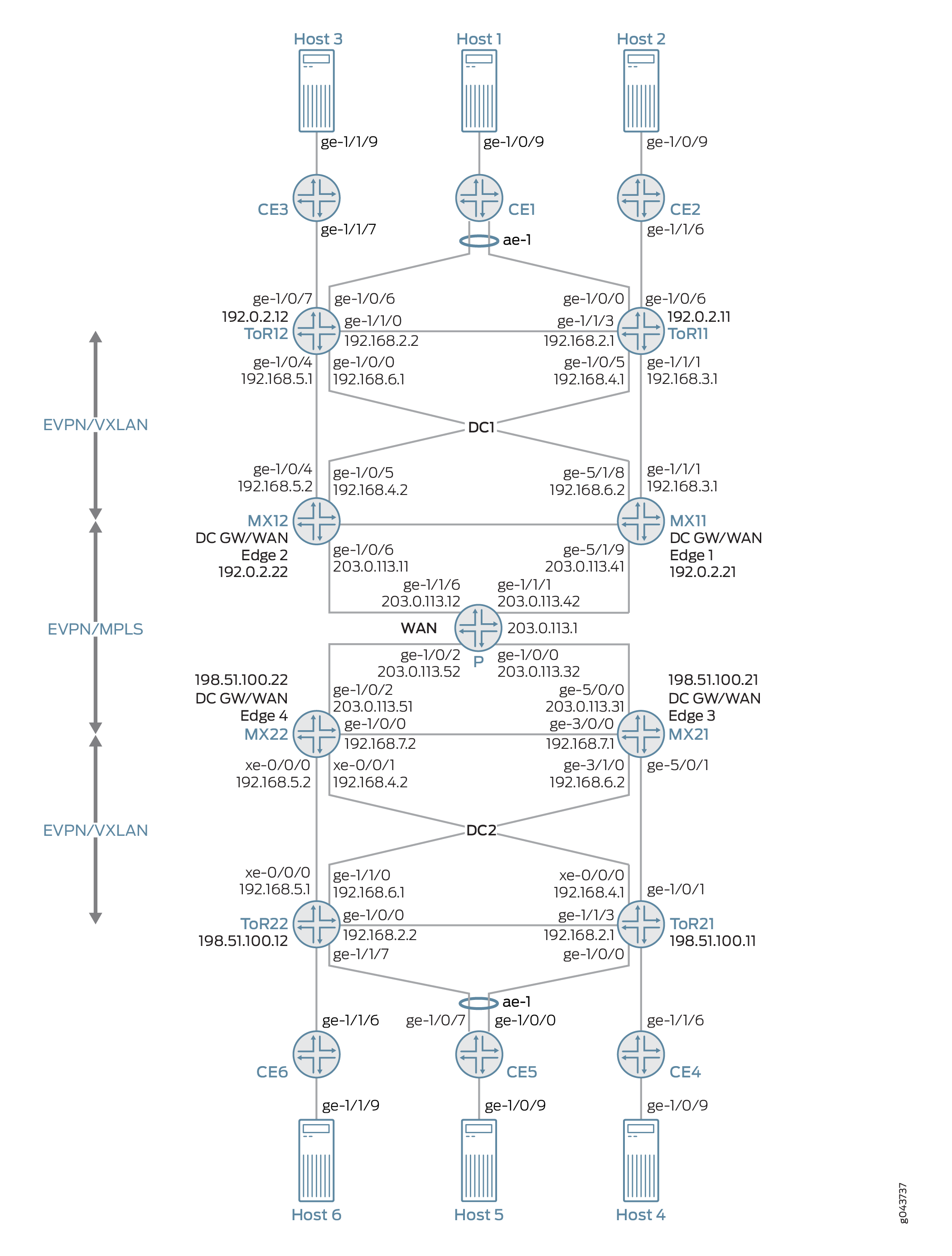
In this illustration,
-
The following devices are a part of the data center EVPN-VXLAN overlay network 1 (DC1):
-
Customer edge devices (CE1, CE2, and CE3) connected to the data center network.
-
VLAN hosts connected to each CE device.
-
MX routers playing the role of top-of-rack (ToR11 and ToR12) routers.
-
MX routers playing the role of the data center gateway router in the EVPN-VXLAN network and as a WAN edge router running MPLS-based EVPN (MX11 and MX12).
-
-
The following devices are a part of the data center EVPN-VXLAN overlay network 2 (DC2):
-
Customer edge devices (CE4, CE5, and CE6) connected to the data center network.
-
VLAN hosts connected to each CE device.
-
MX routers playing the role of top-of-rack (ToR21 and ToR22) routers.
-
MX routers playing the role of the data center gateway router in the EVPN-VXLAN network and as a WAN edge router running MPLS-based EVPN (MX21 and MX22).
-
The interconnection of the data center network is realized on the data center gateway router through a pair of logical tunnel (lt-) interface.
On the data center gateway router, you need to configure a pair of logical tunnel (lt-) interface to interconnect the data center EVPN-VXLAN instance and the WAN MPLS-based EVPN instance: one logical tunnel (lt-) interface is configured as the access interface for EVPN-VXLAN network and the other logical tunnel (lt-) interface as the access interface for MPLS-based EVPN network as shown in the Figure 2.
The support for active-active multi-homing is provided at the data center gateway routers for interconnection.

To configure EVPN-VXLAN and MPLS-based EVPN instances on the logical tunnel (lt-) interface of the data center gateway router, see Example: Interconnecting EVPN-VXLAN Data Center Networks Through a WAN Running EVPN-based MPLS.
Multi-homing on Data Center Gateways
You can configure redundant data center gateways and active-active multi-homing of EVPN-VXLAN network to a WAN running MPLS-based EVPN and active-active multi-homing of MPLS-based EVPN network to EVPN-VXLAN. This allows redundancy between the interconnection of EVPN-VXLAN network and MPLS-based EVPN WAN network. This also enables load-balancing of unicast traffic among the redundant data center gateways in both directions (from EVPN-VXLAN to EVPN-MPLS, as well as from EVPN-MPLS to EVPN-VXLAN). Broadcast, unknown unicast, and multicast (BUM) traffic is forwarded out of the data center by one of the data center gateways.
EVPN Designated Forwarder (DF) Election
To achieve active-active EVPN-VXLAN to EVPN-MPLS interconnect instance and active-active EVPN-MPLS to EVPN-VXLAN instance, the logical tunnel (lt-) interface on the data center gateway router is configured with a non-zero Ethernet Segment Identifier (ESI). The ESI, a 10-octet value that must be unique across the entire network, is configured on a per port basis for the logical tunnel (lt-) interface. As per the EVPN multi-homing procedure defined in the RFC7432, the following routes are advertised for an EVPN instance (EVI):
-
Advertise an Ethernet segment route
-
Advertise an ESI auto-discovery route with a valid split-horizon label and mode set to multi-homing
The standard EVPN DF election procedure described in RFC7432 is considered. The DF election is based on per Ethernet segment for each EVI. The EVPN-VXLAN and EVPN-MPLS run its DF election process independently.
Split Horizon
Split horizon prevents the looping of BUM traffic in a network, see RFC7432. For BUM traffic from core to the data center gateway (EVPN PE) direction, DF floods the BUM traffic to the access (lt- interface) router and non-DF blocks the BUM traffic. When a DF or non-DF receives the BUM traffic coming from access (lt- interface) router, it gets flooded to the core, but DF does not flood BUM traffic received from its non-DF to the access router based on split horizon rules. For a given BUM packet, only one copy is flooded to the access router (lt- interface) and then to the EVPN core through one of the data center gateway routers because EVPN is multi-homed to another EVPN network. The DF filter rule from the first EVPN instance guarantees that only one copy of BUM traffic is forwarded from the DF to the lt-interface before it re-enters the second EVPN instance.
Aliasing
When redundancy is configured in data center gateways, the traffic is load-balanced among redundant data center gateway routers on a per flow basis. MAC address is learned through the data plane using a pair of logical tunnel (lt-) interfaces configured for EVPN-VXLAN instance and EVPN-MPLS instance for data center interconnect. However, the MAC owned by a host is always accessible by all the redundant data center gateways due to the nature of active-active multi-homing and full-mesh of EVPN PEs in both EVPN-VXLAN network and in WAN running EVPN-MPLS. Each EVPN instance on the data center gateway router declares the support of aliasing function for the ESI configured on the logical tunnel (lt-) interface by advertising per EVI auto-discovery route. The aliasing functionality support is defined in the RFC7432.
Figure 3 illustrates a link failure between CE1 and NVE1 but CE1 is still reachable by both data center gateway routers within the data center network (DC1).
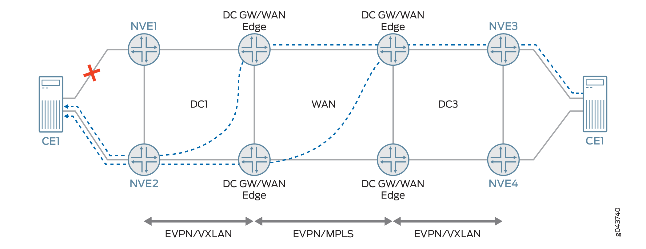
A link failure between a host and its top-of-rack (TOR) devices does not impact the aliasing functionality declared by the data center gateway router as the data center network itself is active-active to the WAN running EVPN-MPLS. As long as the host is connected to another ToR device in the data center network, the host is still accessible by all the other redundant data center gateway routers, so the aliasing functionality applies.
VLAN-Aware Bundle Service
In Junos OS for MX Series, both EVPN-VXLAN and EVPN-MPLS instances support VLAN-aware bundle service with one or more bridge domains. To connect two EVIs with VLAN-aware bundle service through a pair of logical tunnel (lt-) interface, it needs trunk interface support on the logical tunnel (lt-) interface, as well as trunk interface support for both EVPN-VXLAN and EVPN-MPLS instances. A trunk interface on Junos OS MX Series allows a logical interface to accept packets tagged with any VLAN ID specified in a VLAN ID list.
When the trunk mode is used for the logical tunnel (lt-) interface, the frames going out of the logical tunnel (lt-) interface trunk port from the first EVPN virtual switch are tagged with the appropriate VLAN tag; going through its peer logical tunnel (lt-) interface, the incoming frames to the second virtual switch are inspected and forwarded based on the VLAN tag found within the frame.
The following is a sample configuration to use trunk mode on logical tunnel (lt-) interface to support VLAN-aware bundle service for interconnection of EVPN-VXLAN with a WAN running MPLS-based EVPN:
interfaces lt-1/0/10 {
esi {
    36:36:36:36:36:36:36:36:36:36;
    all-active;
}
unit 3 {
    encapsulation ethernet-bridge;
        peer-unit 4;
        family bridge {
        interface-mode trunk;
        vlan-id-list [ 51 52 ];
    }
}
unit 4 {
    encapsulation ethernet-bridge;
        peer-unit 3;
        family bridge {
        interface-mode trunk;
        vlan-id-list [ 51 52 ];
    }
}
}
The following is a sample configuration of trunk port support for EVPN-VXLAN and EVPN-MPLS:
routing-instances evpn-mpls {
vtep-source-interface lo0.0;
    instance-type virtual-switch;
    interface lt-1/0/10.4;
    route-distinguisher 101:2;
    vrf-target target:2:2;
    protocols {
    evpn {
        extended-vlan-list 51-52;
    }
}
bridge-domains {
    bd1 {
        domain-type bridge;
        vlan-id 51;
    }
    bd2 {
        domain-type bridge;
        vlan-id 52;
    }
}
}
routing-instances red {
vtep-source-interface lo0.0;
    instance-type virtual-switch;
    interface lt-1/0/10.4
    route-distinguisher 101:1;
    vrf-target target:1:1;
    protocols {
    evpn {
        encapsulation vxlan;
        extended-vni-list all;
    }
}
bridge-domains {
    bd1 {
        domain-type bridge;
            vlan-id 51;
            routing-interface irb.0;
            vxlan {
            vni 51;
                encapsulate-inner-vlan;
                decapsulate-accept-inner-vlan;
        }
    }
    bd2 {
        domain-type bridge;
            vlan-id 52;
            routing-interface irb.1;
            vxlan {
            vni 52;
                encapsulate-inner-vlan;
                decapsulate-accept-inner-vlan;
        }
    }
}
}
Data Center Network Design and Considerations
Before designing a data center network, you need to decide whether to use IGP, or iBGP, or eBGP protocols in the data center network for IP underlay. Another important factor to consider is the AS assignment. The ToR device in the data center network is required to have an AS number that is different than the AS number used in the WAN edge router.
For the overlay network, you need to decide whether to use iBGP, or eBGP, or a combination of both iBGP and eBGP.
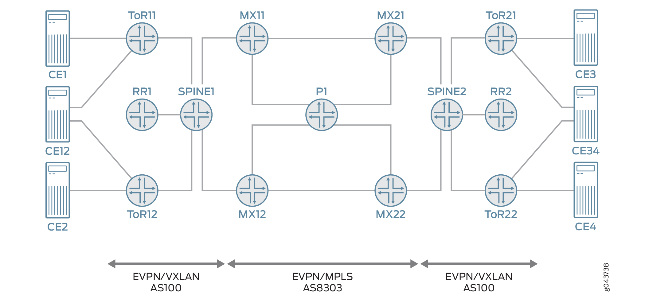
Figure 4 illustrates the MX routers (MX11, MX12, MX21 and MX22) as the data center gateway and WAN edge routers that interconnects EVPN-VXLAN to EVPN-MPLS. Spine switches provide connection for east and west traffic among ToRs so that traffic that does not need to be Layer 3 routed does not go through the MX routers. From a network design perspective, to provide an end-to-end EVPN solution, the following requirements must be met:
Isolate IGP Between EVPN-VXLAN and EVPN-MPLS Segments
When IGP is used in the data center network, you need to isolate the IP network in EVPN-VXLAN from the IP network in the WAN. When IGP is used in the data center, one option is not to run IGP protocol on the interfaces that connects spine switches and MX routers. Instead, an eBGP session with address family inet unicast is used between spine switches and MX routers such that through IGP/eBGP/policy you can leak loopback addresses of ToR and MX routers to each other and still maintain the isolation of IP network in the data center from WAN. In the EVPN-VXLAN segment, IGP is between spine switches and ToRs only. In the EVPN-MPLS segment, IGP is between all the MX routers.
Using iBGP for IP Underlay in the Data Center Network
If the requirement is to not use IGP in the IP underlay in the data center, iBGP with address family inet unicast can be used to replace OSPF between spine switches and ToRs. Between spine switches and data center gateways, you still need to use eBGP for advertising loopback IP.
Using eBGP for the IP Underlay in the Data Center Network
If the requirement is to use eBGP only in the data center, you need to use eBGP with address family inet unicast for the IP underlay. In this case, it is a typical 2 stage CLOS network without spine aggregation layer. Each ToR and data center gateway is assigned a unique AS number. ToR establishes eBGP session with data center gateway routers directly.
Different Autonomous Systems (AS) in EVPN-VXLAN and EVPN-MPLS Network
The following is support for different AS in EVPN-VXLAN and EVPN-MPLS network running iBGP, or eBGP for the IP overlay.
Runing iBGP/eBGP for the Overlay
ToRs and spine switches are in the same AS100 and all MX Series routers are in AS8303. Among ToRs, its EVPN Network Layer Reachability Information (NLRI) is exchanged through iBGP session. A BGP route reflector (RR) is used and each ToR establishes iBGP session with the RR. Data traffic between ToRs that belongs to the same bridge domain goes through spine switch only and it is always 2 hops away. Since the ToRs and spine switches are in the same AS and the MX edge routers are in the different AS, the MX edge router establishes eBGP session to either RR or each ToR directly. By default, route learned from iBGP session (ToRs) are re-advertised to the eBGP (MX routers) and vice versa. BGP next-hop unchanged is enforced when BGP re-advertises EVPN NLRI among iBGP and eBGP session.
Running eBGP only for the Overlay
If the requirement is to run eBGP only in the data center, each ToR is assigned a unique AS number. Each data center gateway router uses a unique AS number on the data center facing side. For the WAN facing side, the same AS number is used, but the AS number would be different from the AS number used for the data center facing side. The AS number may also be reused in each data center.
To prevent an EVPN route in the data center to be advertised to the data center gateway routers in another data center, you must turn on the route constrain in the EVPN-MPLS network. To make BGP route constrain to work, different route target is used for EVPN-VXLAN and EVPN-MPLS network, respectively.