Understanding the SRX4600 Firewall Chassis
The SRX4600 Firewall chassis is a rigid sheet metal structure that houses all the firewall components.
Chassis Physical Specifications
Table 1 summarizes the physical specifications for the firewall chassis.
Description |
Value |
|---|---|
Chassis |
Height: 1.72 in. (4.36 cm) |
Depth
|
|
Width
|
|
Fan module |
Weight: 2.3 lb (1.04 kg) |
AC power supply |
Weight: 3.4 lb (1.54 kg) |
DC power supply |
Weight: 4.4 lb (1.99 kg) |
Firewall weight |
An AC device weighs approximately 38 lb (17.23 kg) |
A DC device weighs approximately 40 lb (18.14 kg) |
|
Form factor |
1 U, standard 19-inch rack-mountable. |
Chassis Front Panel
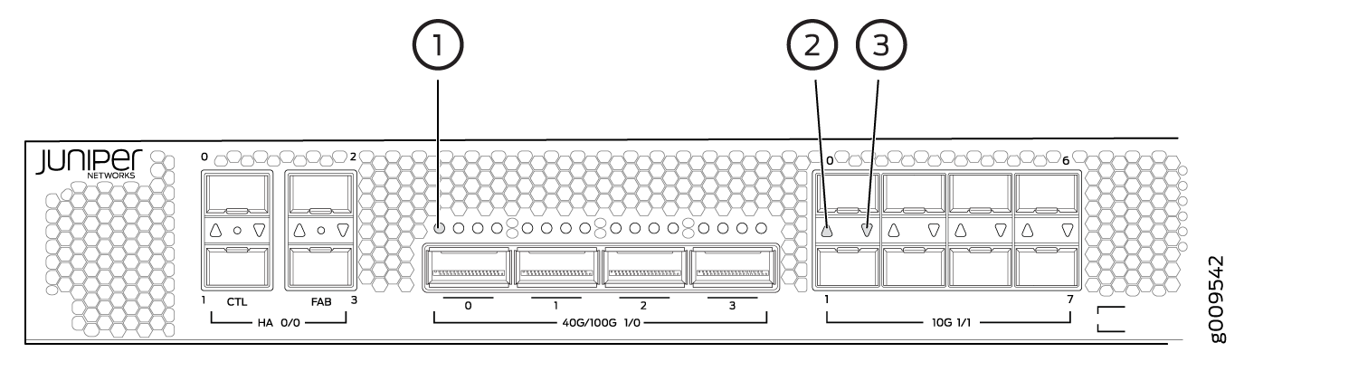
Figure 1 shows the front panel of the SRX4600 Firewall.
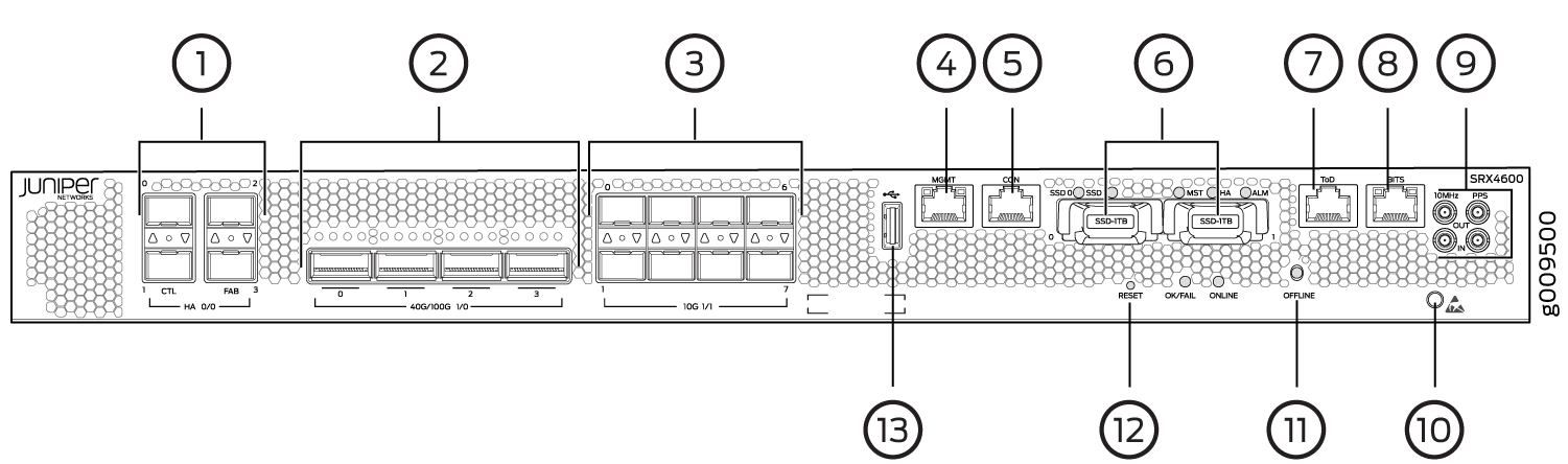
Table 2 lists and describes the front panel components of the firewall.
Number |
Component (Label on the Chassis) |
Description |
|---|---|---|
1 |
Chassis cluster ports (HA) |
Two 1GbE/10GbE (SFP+) chassis cluster control CTL ports and two 1GbE/10GbE (SFP+) dedicated chassis cluster fabric FAB ports. |
2 |
QSFP28 ports |
Four 40/100-Gigabit Ethernet QSFP28 (quad small form-factor pluggable) ports for network traffic. By default each port is configured as a 40-Gigabit Ethernet port. |
3 |
SFP+ ports |
Eight 1/10-Gigabit Ethernet SFP+ ports for network traffic. By default each port is configured as a 10-Gigabit Ethernet port. |
4 |
Management port (MGMT) |
Management port |
5 |
Console port (CON) |
You can connect a laptop to the firewall for CLI management. The port uses an RJ-45 serial connection, is configured as DTE, and supports the RS-232 (EIA-232) standard. |
6 |
SSDs |
The two SSDs are FRUs and they are for storage. |
7 |
ToD |
Time-of-Day RJ-45 port |
8 |
BITS |
BITS RJ-45 port |
9 |
10MHz GPS port |
Output clock at 10 Mhz |
PPS |
1 pulse per second (PPS) output connection for clocking messages |
|
10 |
ESD socket |
For personal safety, while working on the firewall, use the ESD outlet to plug in an ESD grounding strap to prevent your body from sending static charges to the firewall. |
11 |
OFFLINE |
OFFLINE button |
12 |
RESET |
To cold reboot the firewall, press and hold the RESET button for less than 5 seconds. |
13 |
USB 2.0 port |
One USB 2.0 port that accepts a USB storage device. |
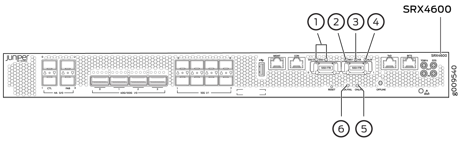
Chassis and Component Status LEDs
Figure 2 shows the SRX4600 Firewall chassis and component status LEDs.
Number |
LED (Label on the Chassis) |
Description |
|---|---|---|
1 |
SSD 0 & SSD 1 |
|
2 |
MST |
|
3 |
HA |
|
4 |
ALM |
|
5 |
ONLINE |
|
6 |
OK/FAIL |
|
Interface Ports LEDs
HA Port LEDs
Each HA port has one Link activity LED below or above it. Figure 3 shows the location of the LEDs and Table 4 describes the LEDs.
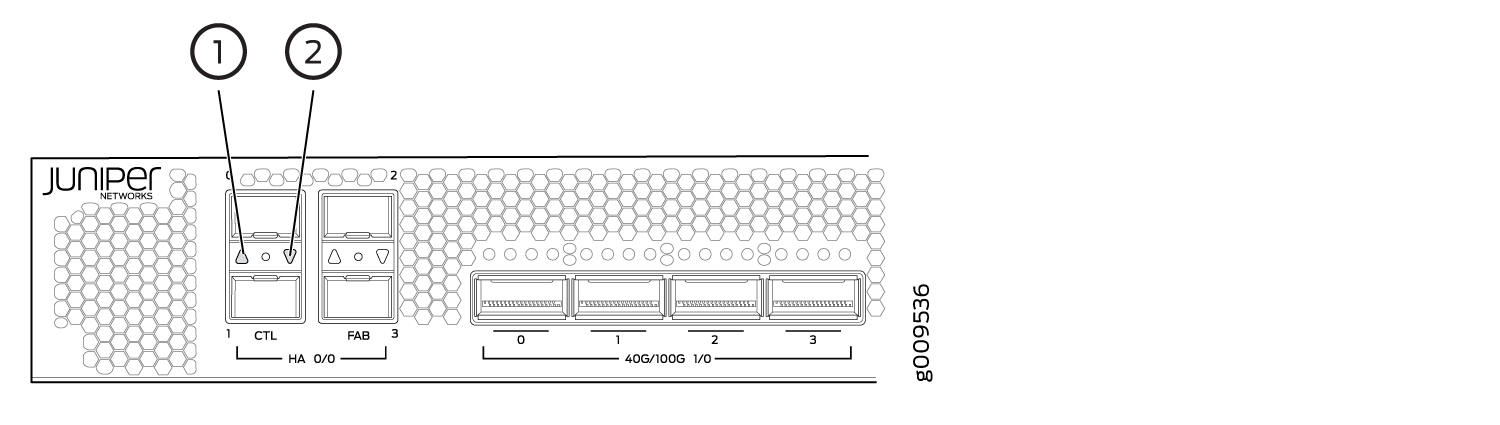
1 — Link activity LED of HA port 0 | 2 — Link activity LED of HA port 1 |
LED |
Description |
|---|---|
Link activity LED |
|
Management Port LEDs
The management port has two LEDs that indicate link activity and status of the management port.
Figure 4 shows the location of the LEDs on the management port and Table 5 describes the LEDs.
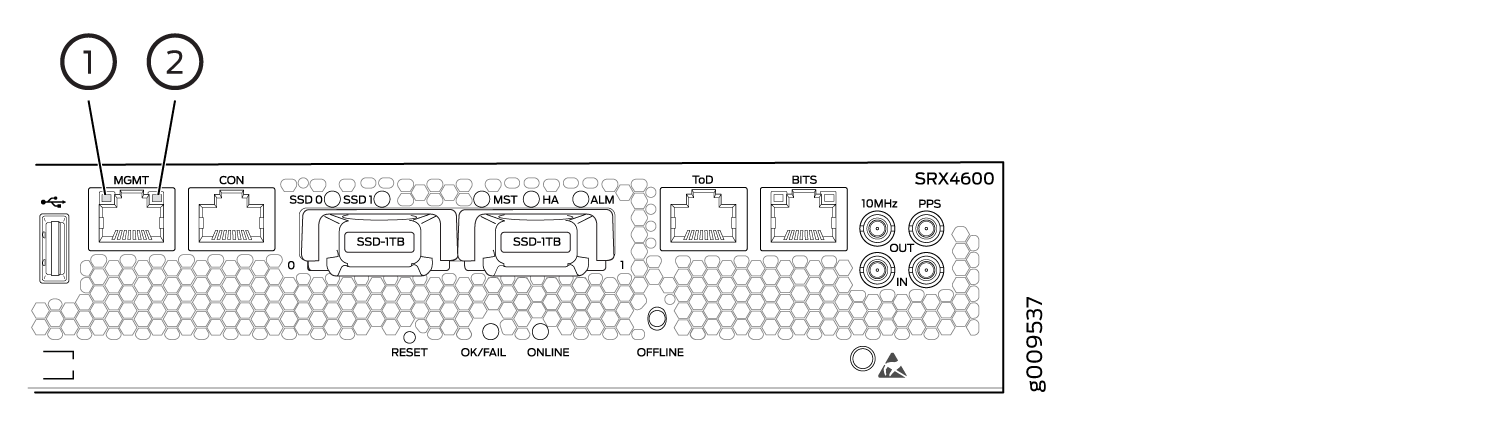
1 — Link activity LED | 2 — Status LED |
LED |
Description |
|---|---|
Link activity LED |
|
Speed |
|
Network Port LEDs
Each QSFP28 port has one link activity LED above it and each SFP+ port has one link activity LED located above or below it. Figure 5 shows the location of the LEDs and Table 6 describes the LEDs.
1 — Link activity LED of QSFP28 port 0 | 3 — Link activity LED of SFP+ port 1 |
2 — Link activity LED of SFP+ port 0 |
LED |
Description |
|---|---|
Link activity LED |
|
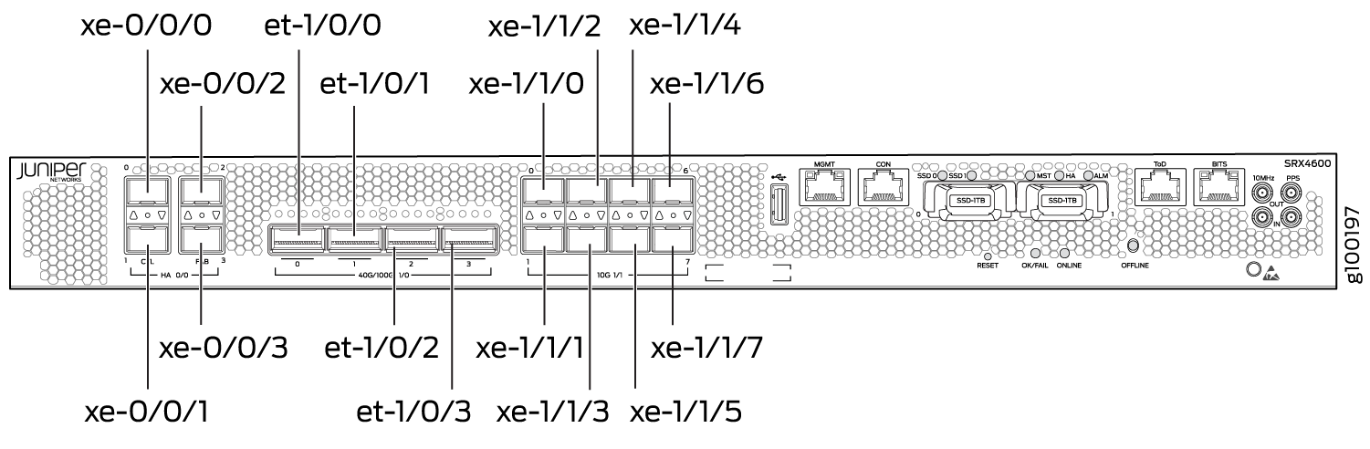
Port and Interface Numbering
Each port on the firewall corresponds to a unique interface name in the CLI. The four Chassis cluster (HA) ports (referred to as PIC 0 ports of FPC 0), four 40/100-Gigabit Ethernet QSFP28 (quad small form-factor pluggable) ports (referred to as PIC 0 ports of FPC 1), and eight 1/10-Gigabit Ethernet SFP+ ports (referred to as PIC 1 ports of FPC 1). Figure 6 shows the SRX4600 Interface Port numbering.
In the syntax of an interface name, a hyphen (-)
separates the media type from the FPC slot number (represented as an FPC in the CLI). The FPC
slot number corresponds to the first number in the interface. The
second number in the interface corresponds to the PIC number. The
last number in the interface matches the port number on the PIC. Slashes
(/) separate the FPC number from the PIC number and port
number:
type-fpc/pic/port
type—Media type, which identifies the network device. For example:
ge—Gigabit Ethernet interface
so—SONET/SDH interface
xe—10-Gigabit Ethernet interface
For a complete list of media types, see Interface Naming Overview.
fpc—FPC number, 0 or 1.
pic—PIC number, 0 or 1.
port—Port number.
The maximum capacity of an SRX4600 Firewall is 400 Gbps, which cannot be oversubscribed. In SRX4600, the network ports are available in two groups (referred to as PICs), with restrictions around the number and type of ports that can be configured without over-subscribtion.
Table 7 lists the different port configurations you can have on SRX4600.
Interface Options |
PIC0 |
PIC1 |
||||||||||
|---|---|---|---|---|---|---|---|---|---|---|---|---|
1/0/0 |
1/0/1 |
1/0/2 |
1/0/3 |
1/1/0 |
1/1/1 |
1/1/2 |
1/1/3 |
1/1/4 |
1/1/5 |
1/1/6 |
1/1/7 |
|
1 |
4x10G or 1x40G |
4x10G or 1x40G |
4x10G or 1x40G |
4x10G or 1x40G |
1G or 10G |
1G or 10G |
1G or 10G |
1G or 10G |
1G or 10G |
1G or 10G |
1G or 10G |
1G or 10G |
2 |
100G |
100G |
4x10G or 1x40G |
4x10G or 1x40G |
1G or 10G |
1G or 10G |
1G or 10G |
1G or 10G |
1G or 10G |
1G or 10G |
1G or 10G |
1G or 10G |
3 |
100G |
100G |
100G |
100G |
- |
- |
- |
- |
- |
- |
- |
- |
For information on port configurations and rate-selectability, see SRX4600 Port Speed Overview and Understanding the SRX4600 Firewall Chassis.
Chassis Rear Panel
Figure 7 shows the rear panel of the SRX4600 Firewall with AC power supplies.
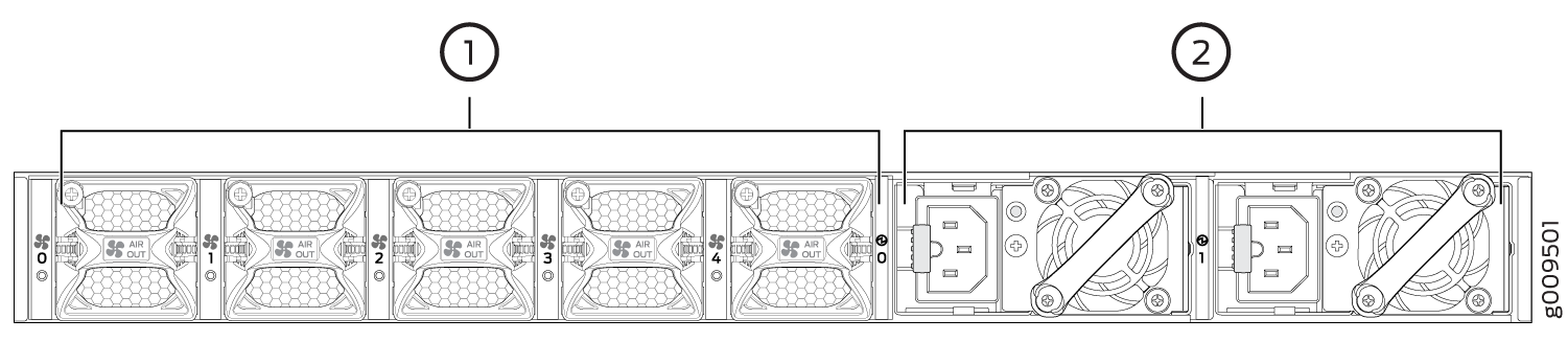
1 — Fan modules | 2 — AC power supplies |
Figure 8 shows the rear panel of the SRX4600 Firewall with DC power supplies.
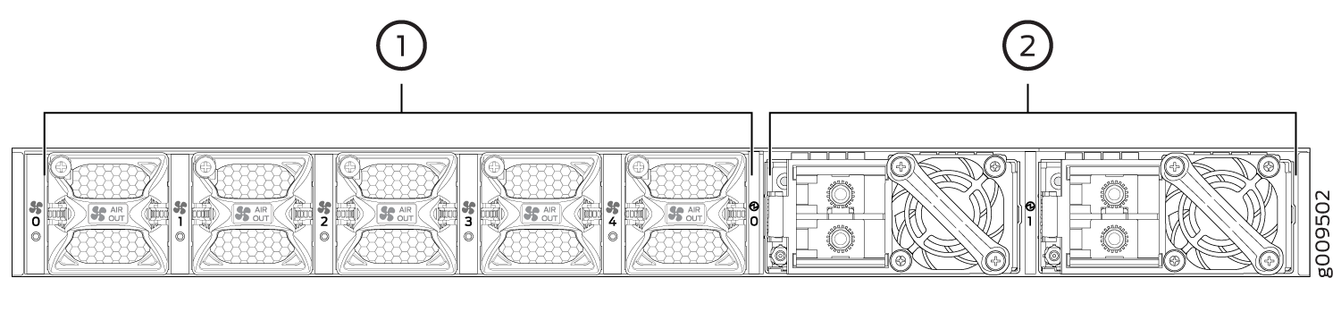
1 — Fan modules | 2 — DC power supplies |
Table 8 lists and describes the rear panel components of the firewall.
Component |
Description |
|---|---|
Fan modules |
Five airflow out (AFO) fan modules (4+1 redundancy). Five fan modules for cooling the firewall and its components. Four fan modules are required for proper air flow across the chassis internal components. The fifth fan module provides redundancy. |
PSUs (Power Supply Units) |
Two power supply slots. Two 1600W AC or two 1100W DC power supply units (1+1 redundancy) are provided with the firewall. |